1993 CHEVROLET PLYMOUTH ACCLAIM Index
[x] Cancel search: IndexPage 296 of 2438

HYDRAULIC SYSTEM CONTROL VALVES INDEX
page page
General Information ....................... 10
Hydraulic System Service Procedures ......... 11 Pressure Differential Warning Light Switch
...... 10
GENERAL INFORMATION
All models equipped with a Bendix Antilock 4 Brake
System have 2 screw-in type proportioning valves.
There is 1 valve for each individual rear wheel hydrau-
lic brake line. The proportioning valves are mounted
directly into the rear brake outlet ports of the modula-
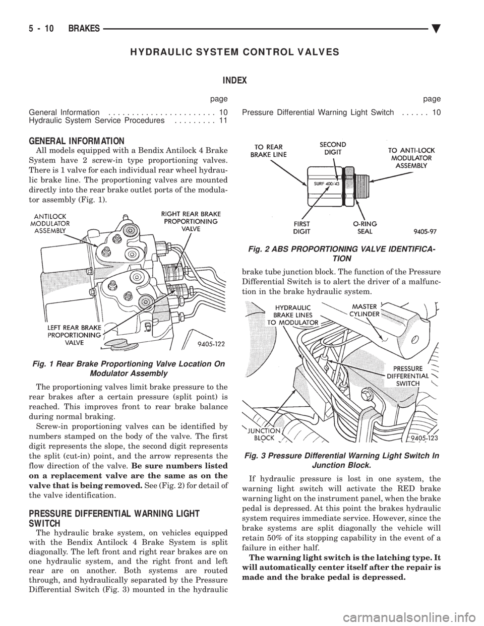
tor assembly (Fig. 1).
The proportioning valves limit brake pressure to the
rear brakes after a certain pressure (split point) is
reached. This improves front to rear brake balance
during normal braking. Screw-in proportioning valves can be identified by
numbers stamped on the body of the valve. The first
digit represents the slope, the second digit represents
the split (cut-in) point, and the arrow represents the
flow direction of the valve. Be sure numbers listed
on a replacement valve are the same as on the
valve that is being removed. See (Fig. 2) for detail of
the valve identification.
PRESSURE DIFFERENTIAL WARNING LIGHT
SWITCH
The hydraulic brake system, on vehicles equipped
with the Bendix Antilock 4 Brake System is split
diagonally. The left front and right rear brakes are on
one hydraulic system, and the right front and left
rear are on another. Both systems are routed
through, and hydraulically separated by the Pressure
Differential Switch (Fig. 3) mounted in the hydraulic brake tube junction block. The function of the Pressure
Differential Switch is to alert the driver of a malfunc-
tion in the brake hydraulic system.
If hydraulic pressure is lost in one system, the
warning light switch will activate the RED brake
warning light on the instrument panel, when the brake
pedal is depressed. At this point the brakes hydraulic
system requires immediate service. However, since the
brake systems are split diagonally the vehicle will
retain 50% of its stopping capability in the event of a
failure in either half. The warning light switch is the latching type. It
will automatically center itself after the repair is
made and the brake pedal is depressed.
Fig. 1 Rear Brake Proportioning Valve Location On Modulator Assembly
Fig. 2 ABS PROPORTIONING VALVE IDENTIFICA- TION
Fig. 3 Pressure Differential Warning Light Switch InJunction Block.
5 - 10 BRAKES Ä
Page 298 of 2438

BENDIX ANTILOCK 4 BRAKE SYSTEM INDEX
page page
ABS Brake System Diagnostic Features ....... 24
ABS Computer System Service Precautions .... 23
ABS General Service Precautions ............ 23
Antilock Brake System Components .......... 16
Antilock Brake System Definitions ............ 14
Antilock Brakes Operation and Performance .... 15
Antilock System Relays and Warning Lamps .... 19
Bendix Antilock 4 Brake System Diagnostics .... 22
Bleeding Bendix Antilock 4 Brake System ...... 25
Controller Antilock Brake Cab ............... 18
Diagnostic Connector ..................... 19 Electronic Components
.................... 41
General Information ....................... 12
Hydraulic Circuits and Valve Operation ........ 20
Major Components ....................... 14
Mechanical Diagnostics and Service Procedures . 24
Normal Brake System Function .............. 14
On-Car ABS Brake System Service ........... 25
Specifications ........................... 46
System Self-Diagnostics ................... 15
Vehicle Performance ...................... 15
Warning Systems Operation ................ 16
GENERAL INFORMATION
The purpose of an Anti-Lock Brake System is to
prevent wheel lock-up under heavy braking condi-
tions on virtually any type of road surface. Antilock
Braking is desirable because a vehicle which is
stopped without locking its wheels will retain direc-
tional stability and some steering capability. This al-
lows a driver to retain greater control of the vehicle
during heavy braking. This service manual supplement covers the descrip-
tion, diagnostics, and on car service procedures cov-
ering the Bendix Antilock 4 Brake System. If service
is required on the non Antilock related components
of the brake system, refer to the appropriate section
in Group 5 of the Front Wheel Drive Car Engine,
Chassis And Body service manual.
Fig. 1 Bendix Antilock 4 Brake System Components
5 - 12 ANTILOCK 4 BRAKE SYSTEM Ä
Page 352 of 2438

SERVICE PROCEDURES INDEX
page page
Automatic Transmission Oil Coolers .......... 23
Coolant ................................ 14
Coolant Recovery System (CRS) ............. 17
Cooling System Drain, Clean, Flush and Refill . . 15
Electric Fan Motor ........................ 22
Engine Thermostats ....................... 13
Fan Shroud ............................. 23 Fans
.................................. 21
Radiator Hoses .......................... 21
Radiator Pressure Cap .................... 18
Radiators ............................... 18
Testing System for Leaks .................. 17
Water Pumps ........................... 10
WATER PUMPS
A quick test to tell whether or not the pump is
working is to see if the heater warms properly. A
defective pump will not be able to circulate heated
coolant through the long heater hose. The water pump on all models can be replaced
without discharging the air conditioning system.
WATER PUMPÐ2.2/2.5L ENGINE
The 2.2/2.5L engine water pump has a diecast alu-
minum body and housing with a stamped steel impel-
ler. The 2.2/2.5L pump uses an O-ring gasket between
body and housing. The assembly bolts directly to the
block. Cylinder block to water pump sealing is provided
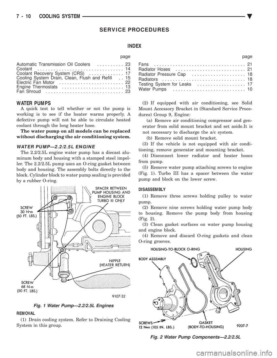
by a rubber O-ring.
REMOVAL (1) Drain cooling system. Refer to Draining Cooling
System in this group. (2) If equipped with air conditioning, see Solid
Mount Accessory Bracket in (Standard Service Proce-
dures) Group 9, Engine: (a) Remove air conditioning compressor and gen-
erator from solid mount bracket and set aside.It is
not necessary to discharge the a/c system. (b) Remove solid mount bracket.
(3) If the vehicle is not equipped with air condi-
tioning, remove generator and mounting bracket. (4) Disconnect lower radiator and heater hoses
from pump. (5) Remove water pump attaching screws to engine
(Fig. 1). Turbo III has a spacer between the water
pump and block on the lower screw.
DISASSEMBLY (1) Remove three screws holding pulley to water
pump. (2) Remove nine screws holding water pump body
to housing. Remove the pump body from housing
(Fig. 2). (3) Clean gasket surfaces on water pump housing
and engine block. (4) Remove and discard O-ring gaskets and clean
O-ring grooves.
Fig. 2 Water Pump ComponentsÐ2.2/2.5L
Fig. 1 Water PumpÐ2.2/2.5L Engines
7 - 10 COOLING SYSTEM Ä
Page 363 of 2438

RADIATOR HOSES
The hoses are removed using Constant Tension
Clamp pliers to compress hose clamp. A hardened, cracked, swollen or restricted hose
should be replaced. Do not damage radiator inlet and
outlet when loosening hoses. Radiator hoses should be routed without any kinks
and indexed as designed. The use of molded hoses is
recommended. Spring type hose clamps are used in all applica-
tions. If replacement is necessary replace with the
original style spring type clamp.
FANS
All models use electric motor driven cooling system
fans. The fan modules include a motor support which
may (depending on model) include a shroud. The
module is fastened to the radiator by screws with
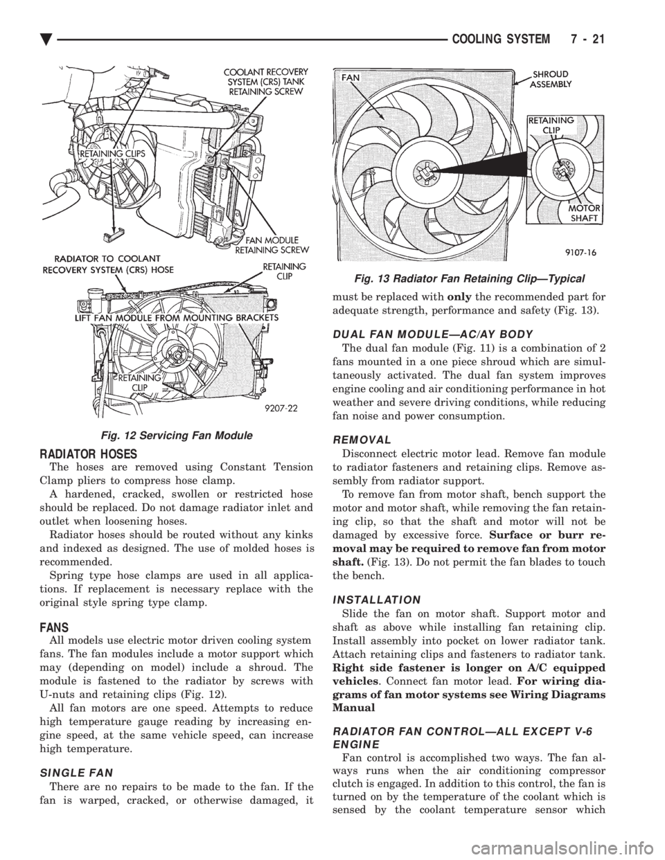
U-nuts and retaining clips (Fig. 12). All fan motors are one speed. Attempts to reduce
high temperature gauge reading by increasing en-
gine speed, at the same vehicle speed, can increase
high temperature.
SINGLE FAN
There are no repairs to be made to the fan. If the
fan is warped, cracked, or otherwise damaged, it must be replaced with
onlythe recommended part for
adequate strength, performance and safety (Fig. 13).
DUAL FAN MODULEÐAC/AY BODY
The dual fan module (Fig. 11) is a combination of 2
fans mounted in a one piece shroud which are simul-
taneously activated. The dual fan system improves
engine cooling and air conditioning performance in hot
weather and severe driving conditions, while reducing
fan noise and power consumption.
REMOVAL
Disconnect electric motor lead. Remove fan module
to radiator fasteners and retaining clips. Remove as-
sembly from radiator support. To remove fan from motor shaft, bench support the
motor and motor shaft, while removing the fan retain-
ing clip, so that the shaft and motor will not be
damaged by excessive force. Surface or burr re-
moval may be required to remove fan from motor
shaft. (Fig. 13). Do not permit the fan blades to touch
the bench.
INSTALLATION
Slide the fan on motor shaft. Support motor and
shaft as above while installing fan retaining clip.
Install assembly into pocket on lower radiator tank.
Attach retaining clips and fasteners to radiator tank.
Right side fastener is longer on A/C equipped
vehicles . Connect fan motor lead. For wiring dia-
grams of fan motor systems see Wiring Diagrams
Manual
RADIATOR FAN CONTROLÐALL EXCEPT V-6 ENGINE
Fan control is accomplished two ways. The fan al-
ways runs when the air conditioning compressor
clutch is engaged. In addition to this control, the fan is
turned on by the temperature of the coolant which is
sensed by the coolant temperature sensor which
Fig. 12 Servicing Fan Module
Fig. 13 Radiator Fan Retaining ClipÐTypical
Ä COOLING SYSTEM 7 - 21
Page 366 of 2438

ACCESSORY DRIVE BELTS INDEX
page page
2.2/2.5L Engine Belts Remove/Install-Adjust .... 24
3.0L Engine Belts Remove/Install and Adjust .... 25
3.3/3.8L and Turbo III Engine Accessory Drive Belt Remove and Install
..................... 26
General Information ....................... 24
GENERAL INFORMATION
PROPER BELT TENSION
Satisfactory performance of the belt driven accesso-
ries depends on belt condition (Fig. 1) and proper belt
tension. Two tensioning methods are given in order
of preference:
² Belt tension gauge method.
² Torque equivalent method.
The belt tension gauge method is usually restricted
to use after the vehicle has been raised on a hoist
and the splash shield has been removed.
BELT TENSION GAUGE METHOD Use belt tensioning Special Tool Kit C-4162 for:
² For conventional belts and Poly-V belts.
Adjust the belt tension for a NeworUsed belt as
prescribed in the Belt Tension Chart.
TORQUE EQUIVALENT METHOD Adjustable accessory brackets provided with a
13mm (1/2 in.) square hole for a torque wrench can
use an equivalent torque value for belt adjustment. Equivalent torque values for adjusting these acces-
sory drive belts are specified on the Belt Tension
Charts .
2.2/2.5L ENGINE BELTS REMOVE/INSTALL-
ADJUST
AIR CONDITIONING COMPRESSOR
(1) Loosen the idler bracket pivot screw A and
locking screws B (Fig. 2) to remove and install belt
and/or adjust belt tension.
ACCESSORY DRIVE BELTS DIAGNOSIS
Fig. 1 Drive Belt Inspection
7 - 24 COOLING SYSTEM Ä
Page 375 of 2438

BATTERY TEST PROCEDURES ON-VEHICLE INDEX
page page
Battery Charging .......................... 7
Battery Load Test ......................... 6
Battery Open Circuit Voltage Test ............. 4
Causes of Battery Discharging ............... 4 General Information
........................ 3
State of Charge Tests ...................... 4
Test Indicator ............................ 3
GENERAL INFORMATION
The battery stores, stabilizes, and produces electri-
cal current to operate various electrical systems in
the vehicle. The determination of whether a battery
is good or bad is made by the battery's ability to ac-
cept a charge. It also must produce high amperage
current output over an extended period to be able to
start the vehicle. The capability of the battery to
store electrical current comes from a chemical reac-
tion. This reaction takes place between the sulfuric
acid solution electrolyte and the lead +/- plates in
each cell of the battery. As the battery discharges,
the plates react with the acid from the electrolyte.
When the charging system charges the battery, the
water is converted to sulfuric acid in the battery. The
amount of acid, specific gravity in the electrolyte can
be measured with a hydrometer. The factory in-
stalled battery is equipped with a built in hydrome-
ter as a test indicator (Figs. 3, 4 and 5) to help in
determining the battery's state of charge. The factory
installed battery also is sealed. Water cannot and
should not be added.
The battery is vented to release gases that is cre-
ated when the battery is being charged and dis-
charged. The battery top, posts, and terminals should
be cleaned when other under hood maintenance is
performed (Fig. 3).
WARNING: DO NOT ASSIST BOOST, CHARGE, ADD
WATER, OR LOAD TEST BATTERY WHEN ELEC- TROLYTE LEVEL IS BELOW THE TOP OF THE
PLATES. PERSONAL INJURY MAY OCCUR.
When the electrolyte level is below the top of the
plates a yellow or bright color indicator in sight glass
(Figs. 4 and 5), the battery must be replaced. Refer
to Test Indicator. The battery must be completely
charged with a green color in sight glass. The top,
posts, and terminals should be properly cleaned be-
fore diagnostic procedures are performed. Also refer
to Group 8B, Battery/Starter/Generator Service.
TEST INDICATOR
The test indicator a hydrometer is viewed through
a sight glass, it is built into the top of battery case
(Figs. 3, 4 and 5). This provides visual information
for battery testing. The test indicator sight glass is to
be used with diagnostic procedures described in this
Group.
Fig. 3 Battery Construction and Test Indicator
Fig. 4 Built in Test Indicator
Fig. 5 Test Indicator Sight Glass
Ä BATTERY/STARTING/CHARGING SYSTEMS DIAGNOSTICS 8A - 3
Page 383 of 2438

STARTER TEST PROCEDURES ON VEHICLE INDEX
page page
Diagnostic Preparation ..................... 11
General Information ....................... 11 Starter Control Circuit Tests
................ 15
Starter Feed Circuit Tests .................. 11
GENERAL INFORMATION
The starting system (Fig. 1) has:
² Ignition switch
² Starter relay (Fig. 2)
² Neutral starting and back-up switch with auto-
matic transmissions
² Clutch pedal mounted starter interlock switch
with manual transmissions
² Wiring harness
² Battery
² Starter motor with an integral solenoid
These components form two separate circuits. A
high amperage circuit that feeds the starter motor up
to 300+ amps, and a control circuit that operates on
less than 20 amps.
DIAGNOSTIC PREPARATION
Before going on with starting system diagnostics,
verify: (1) The battery top, posts, and terminals are clean.
(2) The generator drive belt tension and condition
is correct. (3) The battery state-of-charge is correct.
(4) The battery will pass load test.
(5) The battery cable connections at the starter
and engine block are clean and free from corrosion. (6) The wiring harness connectors and terminals
are clean and free from corrosion. (7) Proper circuit grounding.
(8) Refer to Starter System Diagnostics (Fig. 3).
STARTER FEED CIRCUIT TESTS
The following procedure will require a suitable
volt/ampere tester (Fig. 4).
CAUTION: Ignition system also must be disabled to
prevent engine start while performing the following
tests.
(1) Connect a volt-ampere tester (Fig. 4) to the bat-
tery terminals (Fig. 5). Refer to the operating in-
structions provided with the tester being used. (2) Disable ignition system as follows:
² VEHICLES WITH CONVENTIONAL DISTRIBU-
TORS: Disconnect the ignition coil cable from the
distributor cap. Connect a suitable jumper wire be-
tween the coil cable end-terminal and a good body
ground (Fig. 6).
Fig. 1 Starting Components/Wiring
Fig. 2 Starter Relay
Ä BATTERY/STARTING/CHARGING SYSTEMS DIAGNOSTICS 8A - 11
Page 391 of 2438

GENERATOR TEST PROCEDURES ON VEHICLE INDEX
page page
Charging System Diagnostics (Fig. 1) ......... 19
Current Output Test ...................... 19 Output Wire Resistance Test
................ 19
CHARGING SYSTEM DIAGNOSTICS (Fig. 1)
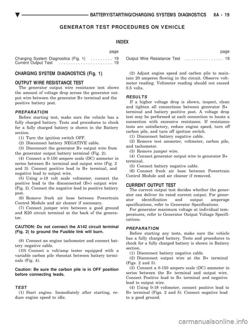
OUTPUT WIRE RESISTANCE TEST
The generator output wire resistance test shows
the amount of voltage drop across the generator out-
put wire between the generator B+ terminal and the
positive battery post.
PREPARATION
Before starting test, make sure the vehicle has a
fully charged battery. Tests and procedures to check
for a fully charged battery is shown in the Battery
section. (1) Turn the ignition switch OFF.
(2) Disconnect battery NEGATIVE cable.
(3) Disconnect the generator B+ output wire from
the generator output battery terminal (Fig. 2). (4) Connect a 0-150 ampere scale (DC) ammeter in
series between B+ terminal and output wire (Fig. 2
and 3). Connect positive lead to B+ terminal, and
negative lead to output wire. (5) Using o-18 volt scale voltmeter, connect the
positive lead to the disconnected (B+) output wire
(Fig. 2). Connect the negative lead to positive battery
post. (6) Remove fresh air hose between Powertrain
Control Module and air cleaner if necessary. (7) Connect jumper wire between a good ground
and K20 circuit terminal at the back of the genera-
tor.
CAUTION: Do not connect the A142 circuit terminal
(Fig. 2) to ground the Fusible link will burn.
(8) Connect an engine tachometer and connect bat-
tery negative cable. (10) Connect a volt/amp tester equipped with a
variable carbon pile rheostat between battery termi-
nals (Fig. 4).
Caution: Be sure the carbon pile is in OFF position
before connecting leads.
TEST
(1) Start engine. Immediately after starting, re-
duce engine speed to idle. (2) Adjust engine speed and carbon pile to main-
tain 20 amperes flowing in the circuit. Observe volt-
meter reading. Voltmeter reading should not exceed
0.5 volts.
RESULTS
If a higher voltage drop is shown, inspect, clean
and tighten all connections between generator B+
terminal and battery positive post. A voltage drop
test may be performed at each connection to locate a
connection with excessive resistance. If resistance
tests are satisfactory, reduce engine speed, turn off
carbon pile, and turn off ignition switch. (1) Disconnect battery negative cable.
(2) Remove test ammeter, voltmeter, carbon pile,
and tachometer. (3) Remove jumper wire.
(4) Connect generator output wire to generator B+
terminal. (5) Connect battery negative cable.
(6) Connect fresh air hose between Powertrain
Control Module and air cleaner if removed.
CURRENT OUTPUT TEST
The current output test decides whether the gener-
ator can deliver its rated current output. For gener-
ator identification and output amperage
specifications, refer to Generator Specifications. For generator maximum voltage at individual tem-
peratures, refer to Generator Output Voltage Specifi-
cations.
PREPARATION
Before starting any tests, make sure the vehicle
has a fully charged battery. Tests and procedures to
check for a fully charged battery is shown in Battery
section. (1) Disconnect battery negative cable.
(2) Disconnect output wire at the B+ terminal
(Figs. 2 and 5). (3) Connect a 0-150 ampere scale (DC) ammeter in
series between the B+ terminal and output wire.
Connect Positive lead to B+ terminal and negative
lead to output wire. (4) Using 0-18 voltmeter, connect positive lead to
B+ terminal (Figs. 2 and 5). Connect negative lead
to a good ground.
Ä BATTERY/STARTING/CHARGING SYSTEMS DIAGNOSTICS 8A - 19