1993 CHEVROLET PLYMOUTH ACCLAIM Index
[x] Cancel search: IndexPage 667 of 2438
EXTERIOR LAMP SYSTEMS INDEX
page page
Daytime Running LampÐCanada Only ........ 25
Headlamp Time Delay System .............. 26
Lamp Outage ModuleÐAA-Body ............. 25 Lamp Outage ModuleÐAll Except AA-Body
..... 25
Lamp Outage System ..................... 25
Removal (Fig. 4) ......................... 25
LAMP OUTAGE SYSTEM
Diagnostics and component relationships for AC,
AG, AJ or AY-Bodies can be found in the Body Di-
agnostic Procedures Manual, Electronic Vehicle In-
formation Center (EVIC) section. For circuit and component locations on AA-body,
refer to the Wiring Diagrams Manual.
LAMP OUTAGE MODULEÐALL EXCEPT AA-BODY
REMOVAL
(1) Remove battery negative cable.
(2) Remove the glove box assembly. Refer to Group
8E, Instrument Panel. (3) Disconnect the wire connector from the lamp
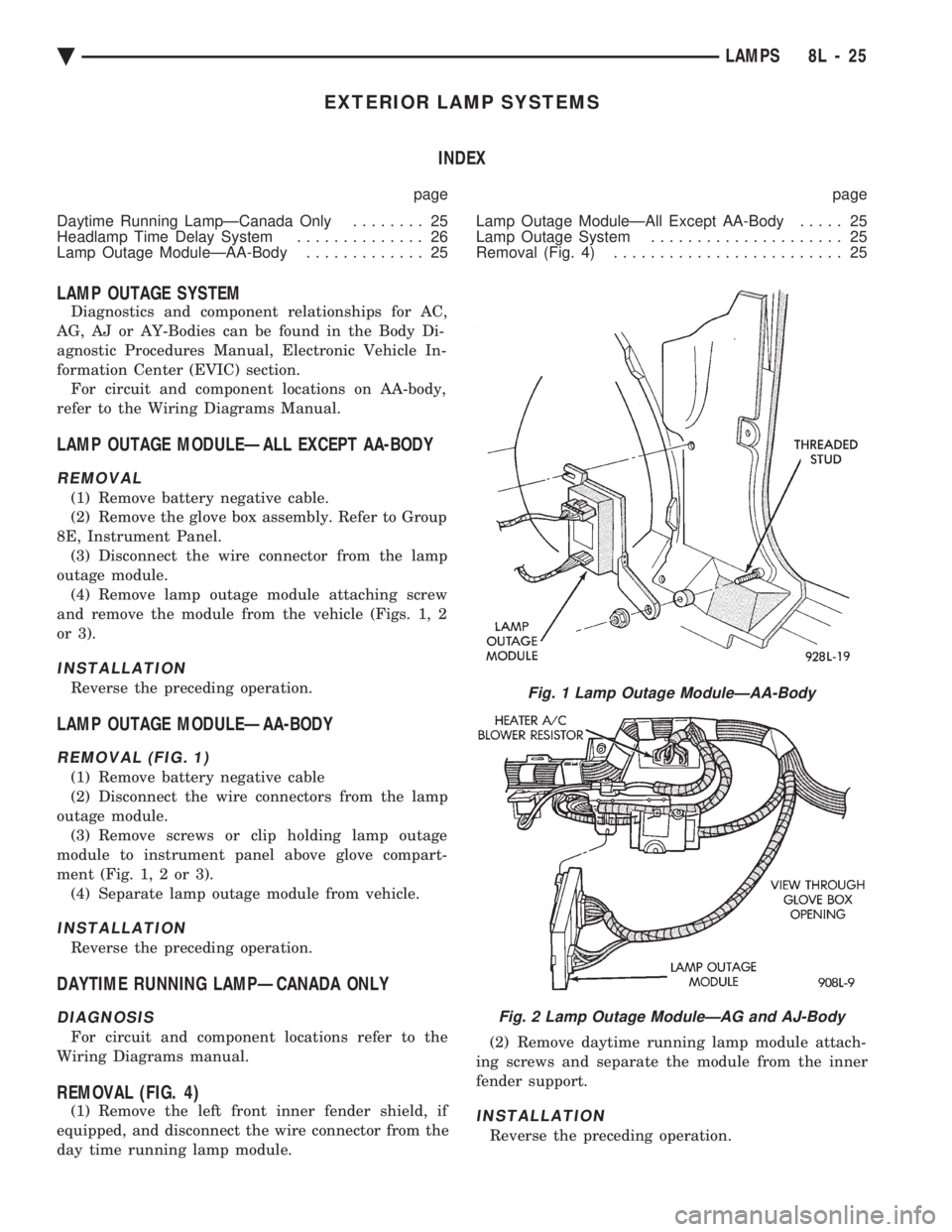
outage module. (4) Remove lamp outage module attaching screw
and remove the module from the vehicle (Figs. 1, 2
or 3).
INSTALLATION
Reverse the preceding operation.
LAMP OUTAGE MODULEÐAA-BODY
REMOVAL (FIG. 1)
(1) Remove battery negative cable
(2) Disconnect the wire connectors from the lamp
outage module. (3) Remove screws or clip holding lamp outage
module to instrument panel above glove compart-
ment (Fig. 1, 2 or 3). (4) Separate lamp outage module from vehicle.
INSTALLATION
Reverse the preceding operation.
DAYTIME RUNNING LAMPÐCANADA ONLY
DIAGNOSIS
For circuit and component locations refer to the
Wiring Diagrams manual.
REMOVAL (FIG. 4)
(1) Remove the left front inner fender shield, if
equipped, and disconnect the wire connector from the
day time running lamp module. (2) Remove daytime running lamp module attach-
ing screws and separate the module from the inner
fender support.INSTALLATION
Reverse the preceding operation.
Fig. 1 Lamp Outage ModuleÐAA-Body
Fig. 2 Lamp Outage ModuleÐAG and AJ-Body
Ä LAMPS 8L - 25
Page 669 of 2438
CONCEALED HEADLAMPS INDEX
page page
Concealed Headlamp MotorÐAC-Body ........ 29
Diagnostic Procedures ..................... 27
General Information ....................... 27 Headlamp DoorÐAC-Body
................. 29
Headlamp DoorÐAY Body ................. 29
Headlamp Drive MotorÐAY Body ............ 30
GENERAL INFORMATION
For proper operation of the Concealed Headlamp
System, refer to the Owner's Manual provided with
the vehicle.
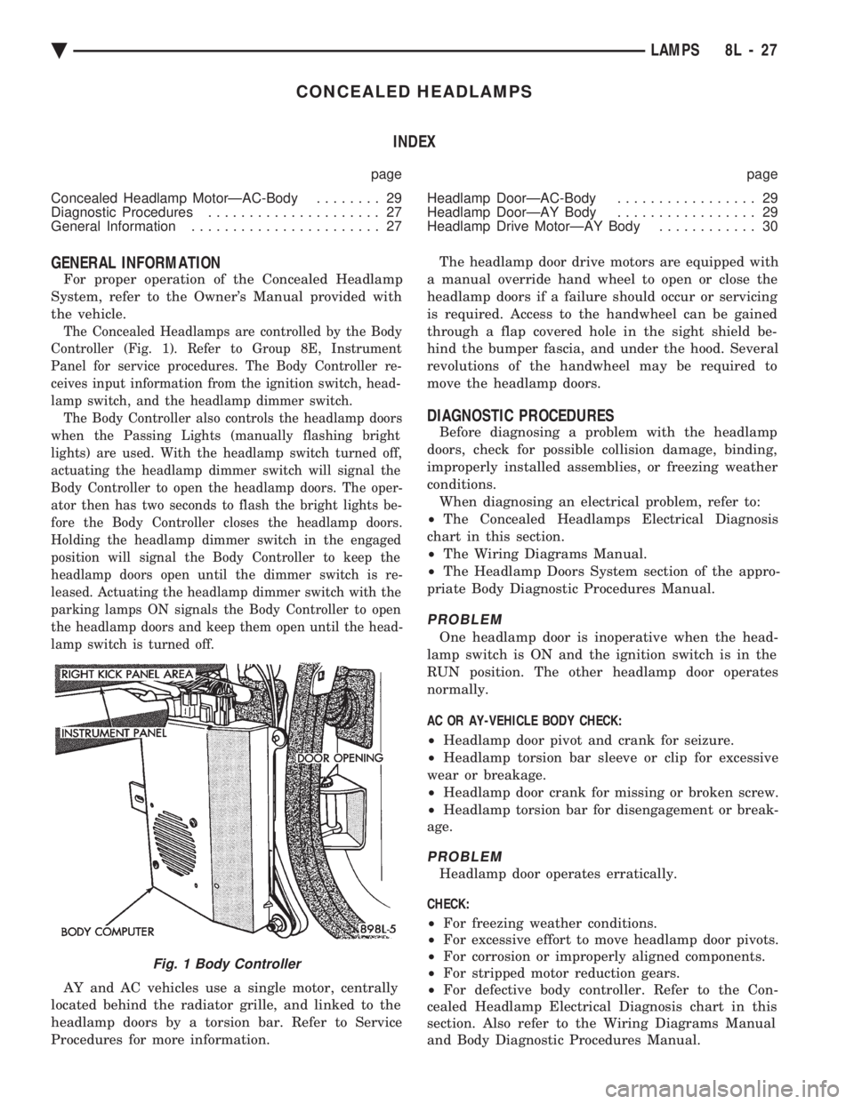
The Concealed Headlamps are controlled by the Body
Controller (Fig. 1). Refer to Group 8E, Instrument
Panel for service procedures. The Body Controller re-
ceives input information from the ignition switch, head-
lamp switch, and the headlamp dimmer switch. The Body Controller also controls the headlamp doors
when the Passing Lights (manually flashing bright
lights) are used. With the headlamp switch turned off,
actuating the headlamp dimmer switch will signal the
Body Controller to open the headlamp doors. The oper-
ator then has two seconds to flash the bright lights be-
fore the Body Controller closes the headlamp doors.
Holding the headlamp dimmer switch in the engaged
position will signal the Body Controller to keep the
headlamp doors open until the dimmer switch is re-
leased. Actuating the headlamp dimmer switch with the
parking lamps ON signals the Body Controller to open
the headlamp doors and keep them open until the head-
lamp switch is turned off.
AY and AC vehicles use a single motor, centrally
located behind the radiator grille, and linked to the
headlamp doors by a torsion bar. Refer to Service
Procedures for more information. The headlamp door drive motors are equipped with
a manual override hand wheel to open or close the
headlamp doors if a failure should occur or servicing
is required. Access to the handwheel can be gained
through a flap covered hole in the sight shield be-
hind the bumper fascia, and under the hood. Several
revolutions of the handwheel may be required to
move the headlamp doors.
DIAGNOSTIC PROCEDURES
Before diagnosing a problem with the headlamp
doors, check for possible collision damage, binding,
improperly installed assemblies, or freezing weather
conditions. When diagnosing an electrical problem, refer to:
² The Concealed Headlamps Electrical Diagnosis
chart in this section.
² The Wiring Diagrams Manual.
² The Headlamp Doors System section of the appro-
priate Body Diagnostic Procedures Manual.
PROBLEM
One headlamp door is inoperative when the head-
lamp switch is ON and the ignition switch is in the
RUN position. The other headlamp door operates
normally.
AC OR AY-VEHICLE BODY CHECK:
² Headlamp door pivot and crank for seizure.
² Headlamp torsion bar sleeve or clip for excessive
wear or breakage.
² Headlamp door crank for missing or broken screw.
² Headlamp torsion bar for disengagement or break-
age.
PROBLEM
Headlamp door operates erratically.
CHECK:
² For freezing weather conditions.
² For excessive effort to move headlamp door pivots.
² For corrosion or improperly aligned components.
² For stripped motor reduction gears.
² For defective body controller. Refer to the Con-
cealed Headlamp Electrical Diagnosis chart in this
section. Also refer to the Wiring Diagrams Manual
and Body Diagnostic Procedures Manual.
Fig. 1 Body Controller
Ä LAMPS 8L - 27
Page 675 of 2438
ILLUMINATED ENTRY SYSTEM INDEX
page page
Body Controller ComputerÐAC, AG, AJ and AY-Body ............................. 34
Diagnostic ProceduresÐAA-Body ............ 33 Diagnostic ProceduresÐAC, AG, AJ and AY-Body . 33
General Information ....................... 33
Illuminated Entry ModuleÐAA-Body ........... 34
GENERAL INFORMATION
AA-BODY
The Illuminated Entry System (on AA Body) actu-
ates the interior courtesy and/or dome lamps (except
for the illuminated ignition switch) by lifting either
front door exterior handle. Lamp illumination is terminated 35 seconds ( 68
seconds later when battery voltage is normal), or by
turning the ignition switch to the run position,
whichever occurs first. When testing the system, all
vehicle doors must be closed to prevent the door jam
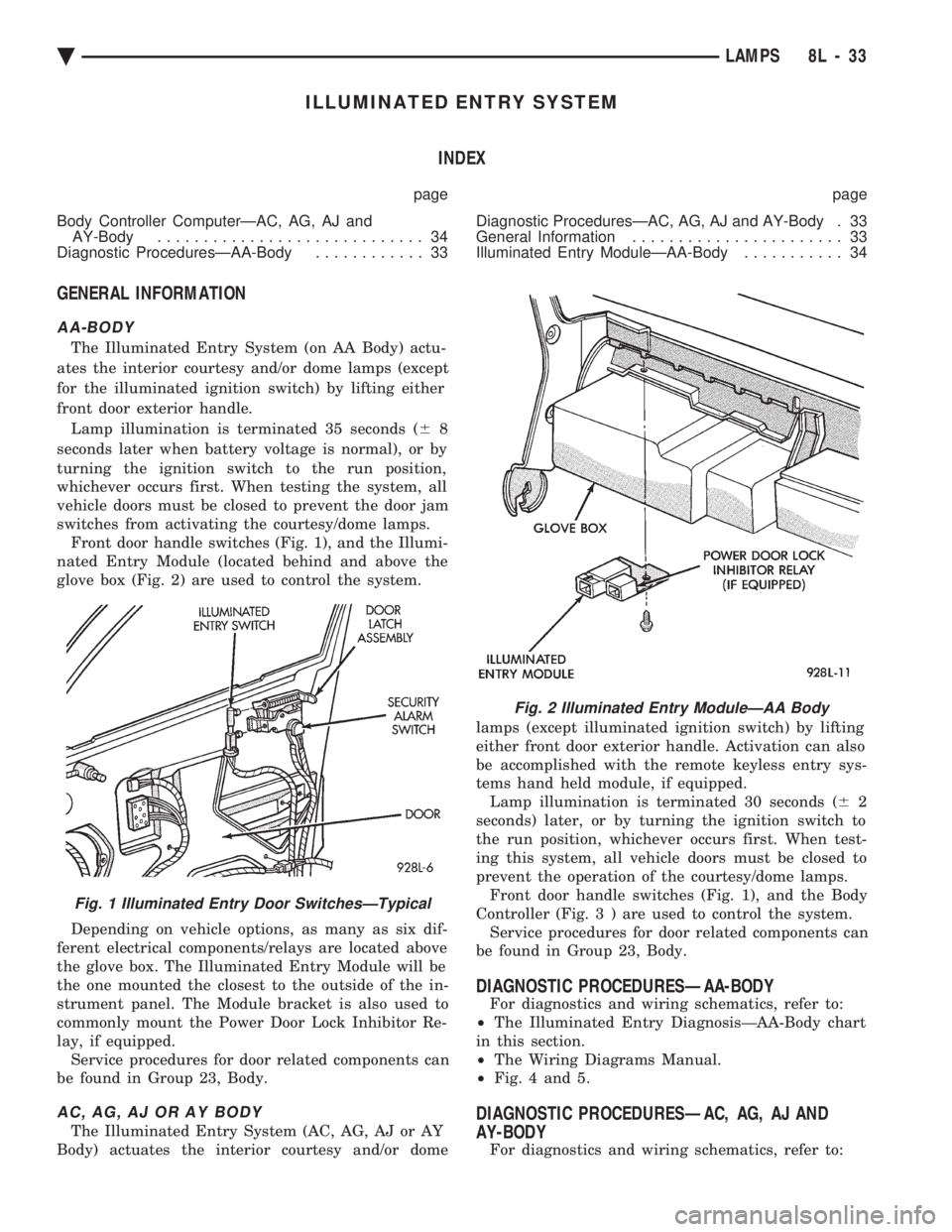
switches from activating the courtesy/dome lamps. Front door handle switches (Fig. 1), and the Illumi-
nated Entry Module (located behind and above the
glove box (Fig. 2) are used to control the system.
Depending on vehicle options, as many as six dif-
ferent electrical components/relays are located above
the glove box. The Illuminated Entry Module will be
the one mounted the closest to the outside of the in-
strument panel. The Module bracket is also used to
commonly mount the Power Door Lock Inhibitor Re-
lay, if equipped. Service procedures for door related components can
be found in Group 23, Body.
AC, AG, AJ OR AY BODY
The Illuminated Entry System (AC, AG, AJ or AY
Body) actuates the interior courtesy and/or dome lamps (except illuminated ignition switch) by lifting
either front door exterior handle. Activation can also
be accomplished with the remote keyless entry sys-
tems hand held module, if equipped. Lamp illumination is terminated 30 seconds ( 62
seconds) later, or by turning the ignition switch to
the run position, whichever occurs first. When test-
ing this system, all vehicle doors must be closed to
prevent the operation of the courtesy/dome lamps. Front door handle switches (Fig. 1), and the Body
Controller (Fig . 3 ) are used to control the system.
Service procedures for door related components can
be found in Group 23, Body.
DIAGNOSTIC PROCEDURESÐAA-BODY
For diagnostics and wiring schematics, refer to:
² The Illuminated Entry DiagnosisÐAA-Body chart
in this section.
² The Wiring Diagrams Manual.
² Fig. 4 and 5.
DIAGNOSTIC PROCEDURESÐAC, AG, AJ AND
AY-BODY
For diagnostics and wiring schematics, refer to:
Fig. 1 Illuminated Entry Door SwitchesÐTypical
Fig. 2 Illuminated Entry ModuleÐAA Body
Ä LAMPS 8L - 33
Page 751 of 2438
GENERAL INFORMATION
CONTENTS
page page
CIRCUIT IDENTIFICATION ................. 3
COMPONENT IDENTIFICATION ............. 3
CONNECTORS ........................... 4
FUSIBLE LINKS ......................... 4
HARNESS REPAIR ....................... 4
LOCATING A SYSTEM .................... 3 SECONDARY IGNITION WIRING
............ 1
SPLICE LOCATIONS ...................... 3
SYMBOLS, FUSES AND RELAYS ........... 7
TROUBLESHOOTING WIRING PROBLEMS .... 4
WIRE CODE IDENTIFICATION .............. 2
WIRING DIAGRAM SHEETS AND INDEXES . . . 1
The wiring diagrams contain the latest information
at the time of publication. Throughout this group ref-
erences may be made to a particular vehicle by letter
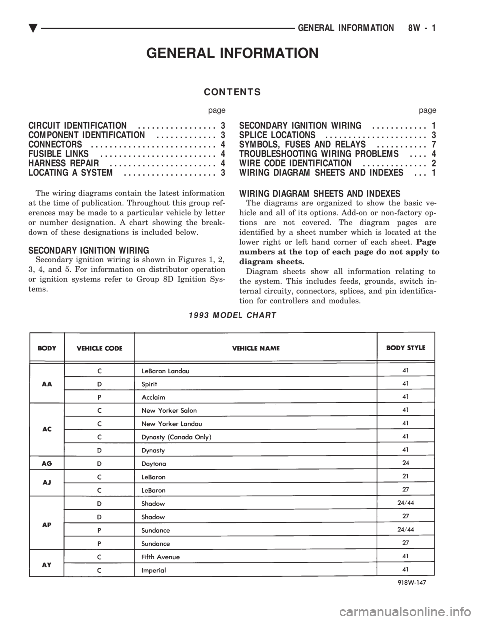
or number designation. A chart showing the break-
down of these designations is included below.
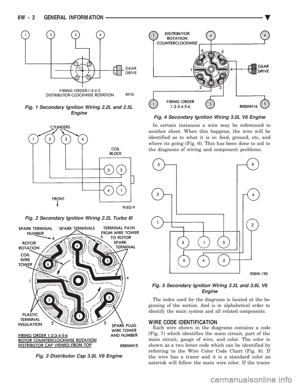
SECONDARY IGNITION WIRING
Secondary ignition wiring is shown in Figures 1, 2,
3, 4, and 5. For information on distributor operation
or ignition systems refer to Group 8D Ignition Sys-
tems.
WIRING DIAGRAM SHEETS AND INDEXES
The diagrams are organized to show the basic ve-
hicle and all of its options. Add-on or non-factory op-
tions are not covered. The diagram pages are
identified by a sheet number which is located at the
lower right or left hand corner of each sheet. Page
numbers at the top of each page do not apply to
diagram sheets. Diagram sheets show all information relating to
the system. This includes feeds, grounds, switch in-
ternal circuity, connectors, splices, and pin identifica-
tion for controllers and modules.
1993 MODEL CHART
Ä GENERAL INFORMATION 8W - 1
Page 752 of 2438
In certain instances a wire may be referenced to
another sheet. When this happens, the wire will be
identified as to what it is ie: feed, ground, etc, and
where its going (Fig. 6). This has been done to aid in
the diagnosis of wiring and component problems.
The index used for the diagrams is located at the be-
ginning of the section. And is in alphabetical order to
identify the main system and all related components.
WIRE CODE IDENTIFICATION
Each wire shown in the diagrams contains a code
(Fig. 7) which identifies the main circuit, part of the
main circuit, gauge of wire, and color. The color is
shown as a two letter code which can be identified by
referring to the Wire Color Code Chart (Fig. 8). If
the wire has a tracer and it is a standard color an
asterisk will follow the main wire color. If the tracer
Fig. 2 Secondary Ignition Wiring 2.2L Turbo III
Fig. 3 Distributor Cap 3.0L V6 Engine
Fig. 1 Secondary Ignition Wiring 2.2L and 2.5L Engine
Fig. 4 Secondary Ignition Wiring 3.0L V6 Engine
Fig. 5 Secondary Ignition Wiring 3.3L and 3.8L V6 Engine
8W - 2 GENERAL INFORMATION Ä
Page 753 of 2438

is non-standard the main wire color will have a slash
(/) after it followed by the tracer color.
CIRCUIT IDENTIFICATION
All circuits in the diagrams use an alpha/numeric
code to identify the wire and its function. To identify
which circuit code applies to a system, refer to the
Circuit Identification Code Chart. This chart shows
the main circuits only and does not show the second-
ary codes that may apply to some models.
LOCATING A SYSTEM
To locate a system or component in the diagrams,
refer to the alphabetical index at the front of the di-
agrams. Determine the diagram sheet number. Sheet
numbers are located at the lower right or left hand
corner of each sheet. Page numbers at the top of
the page do not apply to diagram sheets. The diagram index identifies the main system and
all components in that system. There are also sec-
tions of the index that identify specific components
only (for example modules, lamps, etc.). Refer to a
components name in the index if you are unclear as
to what a system may be called. Diagram pages are arranged starting with the bat-
tery and fuses. Then working into charging, starting,
and ignition systems. After this they start at the
front of the vehicle and work to rear of the vehicle.
The diagrams end with connector identification
pages.
COMPONENT IDENTIFICATION
When looking for a components location on the ve-
hicle refer to the wiring and components section.
This section shows the wire harness routing and the
components location in the vehicle. To use this sec-
tion refer to the wiring diagrams for the location of
the component. Then use the component identifica-
tion index to locate the proper figure number.
SPLICE LOCATIONS
Splices are indicated in the diagrams by a diamond
with a splice circuit code within it (Fig. 9 example 1).
If there is more than one splice per circuit a small
box will be connected to it with the splice number in
it (Fig. 9 example 2). To locate a splice in the wiring harness determine
the splice number from the wiring diagrams then re-
fer to the splice location index. This section shows
the general location of the splice in the harness.
Fig. 6 Wiring Diagram Page Sample
Fig. 7 Wire Color Code Identification
Fig. 8 Wire Color Code Chart
Ä GENERAL INFORMATION 8W - 3
Page 759 of 2438
FUSE CHARTS AND RELAY BANKS
INDEX
Caption Fig.
Fuse Block and Relay Bank AA Body .................1
Fuse Block AC, AY Body .........................2
Fuse Block AG, AJ Body .........................3
Fuse Block and Relay Bank AP Body .................4Caption Fig.
Power Distribution Center AC, AY Body ................7
Power Distribution Center AG, AJ Body ................8
Relay Bank AC, AY Body .........................5
Relay Bank AG, AJ Body .........................6
Ä FUSE CHARTS AND RELAY BANKS 8W - 9
Page 769 of 2438
WIRING AND COMPONENT IDENTIFICATION
CONTENTS
page page
AA BODY C, D, P ...................... 19
AC BODY C,D ......................... 37
AG BODY ............................. 61 AJ BODY
.............................. 77
AP BODY D, P ......................... 94
AY BODY-C ........................... 111
The wiring and components shown in this section
are divided into groups by vehicle line. When locat-
ing a specific harness routing or component, first
turn to the appropriate index, then look up the fig-
ure number that applies.Page numbers at the top of each page do not refer to figure numbers.
Throughout this section references may be made to
a particular vehicle by letter or number designation.
A chart showing the breakdown of these is shown in
the general information section.
AA BODY C, D, P
Caption Fig.
Anti Lock Brake System Wiring .....................4
Body Left Side Wiring ...........................6
Body Right Side Wiring ..........................5
Deck Lid Wiring ..............................1
Door Wiring (Body Side) .........................7
Door Wiring (Front) ............................8
Door Wiring (Rear) ............................9
Engine Compartment Wiring ......................16
Engine Wiring 2.5L ............................19
Engine Wiring 2.5L Flex Fuel ......................20Caption Fig.
Engine Wiring 3.0L ............................21
Front End Lighting ............................22
Ground Strap Locations .........................15
Instrument Panel Wiring .................. .11, 12, 13
Rear End Wiring ..............................2
Steering Column Wiring .........................10
Transmission Wiring ...........................17
Transmission Wiring ETAX .......................18
Trunk Wiring ................................3
Underhood Lamp Wiring ........................14
Ä WIRING AND COMPONENT IDENTIFICATION 8W - 19