1993 CHEVROLET PLYMOUTH ACCLAIM Index
[x] Cancel search: IndexPage 1589 of 2438
CYLINDER HEAD COVER AND CURTAIN
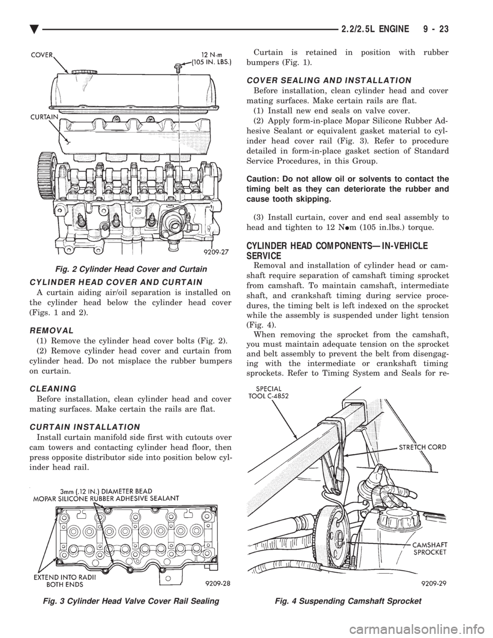
A curtain aiding air/oil separation is installed on
the cylinder head below the cylinder head cover
(Figs. 1 and 2).
REMOVAL
(1) Remove the cylinder head cover bolts (Fig. 2).
(2) Remove cylinder head cover and curtain from
cylinder head. Do not misplace the rubber bumpers
on curtain.
CLEANING
Before installation, clean cylinder head and cover
mating surfaces. Make certain the rails are flat.
CURTAIN INSTALLATION
Install curtain manifold side first with cutouts over
cam towers and contacting cylinder head floor, then
press opposite distributor side into position below cyl-
inder head rail. Curtain is retained in position with rubber
bumpers (Fig. 1).
COVER SEALING AND INSTALLATION
Before installation, clean cylinder head and cover
mating surfaces. Make certain rails are flat. (1) Install new end seals on valve cover.
(2) Apply form-in-place Mopar Silicone Rubber Ad-
hesive Sealant or equivalent gasket material to cyl-
inder head cover rail (Fig. 3). Refer to procedure
detailed in form-in-place gasket section of Standard
Service Procedures, in this Group.
Caution: Do not allow oil or solvents to contact the
timing belt as they can deteriorate the rubber and
cause tooth skipping.
(3) Install curtain, cover and end seal assembly to
head and tighten to 12 N Im (105 in.lbs.) torque.
CYLINDER HEAD COMPONENTSÐIN-VEHICLE
SERVICE
Removal and installation of cylinder head or cam-
shaft require separation of camshaft timing sprocket
from camshaft. To maintain camshaft, intermediate
shaft, and crankshaft timing during service proce-
dures, the timing belt is left indexed on the sprocket
while the assembly is suspended under light tension
(Fig. 4). When removing the sprocket from the camshaft,
you must maintain adequate tension on the sprocket
and belt assembly to prevent the belt from disengag-
ing with the intermediate or crankshaft timing
sprockets. Refer to Timing System and Seals for re-Fig. 2 Cylinder Head Cover and Curtain
Fig. 3 Cylinder Head Valve Cover Rail SealingFig. 4 Suspending Camshaft Sprocket
Ä 2.2/2.5L ENGINE 9 - 23
Page 1632 of 2438
3.0L ENGINE INDEX
page page
Accessory Drive Belt Service ................ 70
Auto Lash Adjuster ....................... 75
Camshaft Service ........................ 76
Checking Engine Oil Pressure ............... 93
Crankshaft and Cylinder Block, Assembly Service . 86
Cylinder Block ........................... 89
Cylinder Head ........................... 78
Cylinder Head and Camshaft Service ......... 75
Engine Assembly ......................... 69
Engine Lubrication System ................. 91
Engine Mounts .......................... 68 Engine Specifications
..................... 95
General Information ....................... 66
Oil Filter and Bracket ..................... 94
Oil Pan ................................ 92
Oil Pump Service ........................ 92
Piston and Connecting Rod Assembly Service . . . 82
Timing Belt InspectionÐIn Vehicle ............ 72
Timing Belt Service ....................... 72
Valve Service ........................... 80
GENERAL INFORMATION
ENGINE IDENTIFICATION NUMBER OR CODE
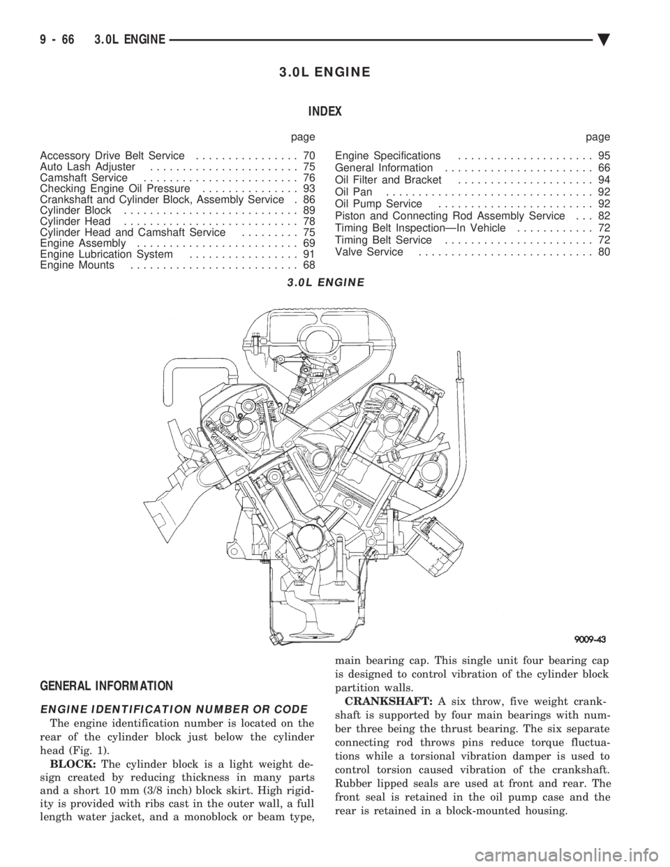
The engine identification number is located on the
rear of the cylinder block just below the cylinder
head (Fig. 1). BLOCK: The cylinder block is a light weight de-
sign created by reducing thickness in many parts
and a short 10 mm (3/8 inch) block skirt. High rigid-
ity is provided with ribs cast in the outer wall, a full
length water jacket, and a monoblock or beam type, main bearing cap. This single unit four bearing cap
is designed to control vibration of the cylinder block
partition walls.
CRANKSHAFT: A six throw, five weight crank-
shaft is supported by four main bearings with num-
ber three being the thrust bearing. The six separate
connecting rod throws pins reduce torque fluctua-
tions while a torsional vibration damper is used to
control torsion caused vibration of the crankshaft.
Rubber lipped seals are used at front and rear. The
front seal is retained in the oil pump case and the
rear is retained in a block-mounted housing.
3.0L ENGINE
9 - 66 3.0L ENGINE Ä
Page 1658 of 2438
OIL PAN
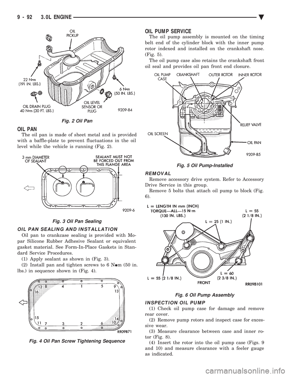
The oil pan is made of sheet metal and is provided
with a baffle-plate to prevent fluctuations in the oil
level while the vehicle is running (Fig. 2).
OIL PAN SEALING AND INSTALLATION
Oil pan to crankcase sealing is provided with Mo-
par Silicone Rubber Adhesive Sealant or equivalent
gasket material. See Form-In-Place Gaskets in Stan-
dard Service Procedures. (1) Apply sealant as shown in (Fig. 3).
(2) Install pan and tighten screws to 6 N Im (50 in.
lbs.) in sequence shown in (Fig. 4).
OIL PUMP SERVICE
The oil pump assembly is mounted on the timing
belt end of the cylinder block with the inner pump
rotor indexed and installed on the crankshaft nose.
(Fig. 5). The oil pump case also retains the crankshaft front
oil seal and provides oil pan front end closure.
REMOVAL
Remove accessory drive system. Refer to Accessory
Drive Service in this group. Remove 5 bolts that attach oil pump to block (Fig.
6).
INSPECTION OIL PUMP
(1) Check oil pump case for damage and remove
rear cover. (2) Remove pump rotors and inspect case for exces-
sive wear. (3) Measure clearance between case and inner ro-
tor (Fig. 8). (4) Insert the rotor into the oil pump case (Figs. 9
and 10) and measure clearance with a feeler gauge
as indicated.
Fig. 2 Oil Pan
Fig. 3 Oil Pan Sealing
Fig. 4 Oil Pan Screw Tightening Sequence
Fig. 5 Oil Pump-Installed
Fig. 6 Oil Pump Assembly
9 - 92 3.0L ENGINE Ä
Page 1664 of 2438
3.3/3.8L ENGINE INDEX
page page
Camshaft .............................. 112
Camshaft BearingsÐEngine Removed From Vehicle .............................. 113
Checking Engine Oil Pressure .............. 125
Connecting Rods ........................ 118
Crankshaft Oil Seals Service ............... 121
Crankshaft Service ...................... 118
Cylinder Block, Piston and Connecting Rod Assembly Service ...................... 114
Cylinder Heads ......................... 102
Engine Assembly ........................ 101
Engine Core Oil and Cam Plugs ............ 113
Engine Lubrication System ................ 122 Engine Mounts
.......................... 99
Engine Specifications ..................... 126
General Information ....................... 98
Hydraulic Tappets ....................... 108
Installing Piston and Connecting Rod Assembly . 117
Intake Manifold Sealing ................... 104
Oil Filter .............................. 125
Oil Pan Service ......................... 122
Oil Pump Service ....................... 123
Rocker Arms and Shaft Assembly ........... 102
Timing Chain Cover, Oil Seal and Chain ...... 109
Valve Service .......................... 104
Valve Timing ........................... 109
GENERAL INFORMATION
ENGINE IDENTIFICATION NUMBER OR CODE
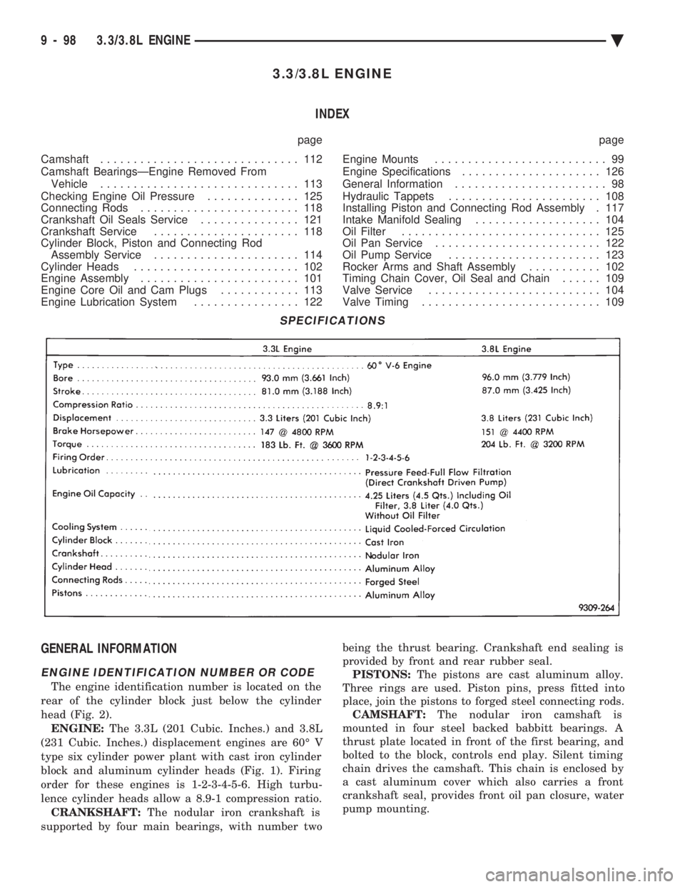
The engine identification number is located on the
rear of the cylinder block just below the cylinder
head (Fig. 2). ENGINE: The 3.3L (201 Cubic. Inches.) and 3.8L
(231 Cubic. Inches.) displacement engines are 60É V
type six cylinder power plant with cast iron cylinder
block and aluminum cylinder heads (Fig. 1). Firing
order for these engines is 1-2-3-4-5-6. High turbu-
lence cylinder heads allow a 8.9-1 compression ratio. CRANKSHAFT: The nodular iron crankshaft is
supported by four main bearings, with number two being the thrust bearing. Crankshaft end sealing is
provided by front and rear rubber seal. PISTONS: The pistons are cast aluminum alloy.
Three rings are used. Piston pins, press fitted into
place, join the pistons to forged steel connecting rods. CAMSHAFT: The nodular iron camshaft is
mounted in four steel backed babbitt bearings. A
thrust plate located in front of the first bearing, and
bolted to the block, controls end play. Silent timing
chain drives the camshaft. This chain is enclosed by
a cast aluminum cover which also carries a front
crankshaft seal, provides front oil pan closure, water
pump mounting.
SPECIFICATIONS
9 - 98 3.3/3.8L ENGINE Ä
Page 1679 of 2438
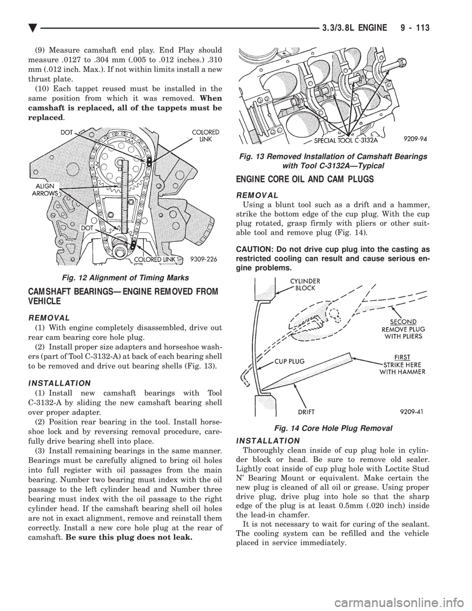
(9) Measure camshaft end play. End Play should
measure .0127 to .304 mm (.005 to .012 inches.) .310
mm (.012 inch. Max.). If not within limits install a new
thrust plate. (10) Each tappet reused must be installed in the
same position from which it was removed. When
camshaft is replaced, all of the tappets must be
replaced .
CAMSHAFT BEARINGSÐENGINE REMOVED FROM
VEHICLE
REMOVAL
(1) With engine completely disassembled, drive out
rear cam bearing core hole plug. (2) Install proper size adapters and horseshoe wash-
ers (part of Tool C-3132-A) at back of each bearing shell
to be removed and drive out bearing shells (Fig. 13).
INSTALLATION
(1) Install new camshaft bearings with Tool
C-3132-A by sliding the new camshaft bearing shell
over proper adapter. (2) Position rear bearing in the tool. Install horse-
shoe lock and by reversing removal procedure, care-
fully drive bearing shell into place. (3) Install remaining bearings in the same manner.
Bearings must be carefully aligned to bring oil holes
into full register with oil passages from the main
bearing. Number two bearing must index with the oil
passage to the left cylinder head and Number three
bearing must index with the oil passage to the right
cylinder head. If the camshaft bearing shell oil holes
are not in exact alignment, remove and reinstall them
correctly. Install a new core hole plug at the rear of
camshaft. Be sure this plug does not leak.
ENGINE CORE OIL AND CAM PLUGS
REMOVAL
Using a blunt tool such as a drift and a hammer,
strike the bottom edge of the cup plug. With the cup
plug rotated, grasp firmly with pliers or other suit-
able tool and remove plug (Fig. 14).
CAUTION: Do not drive cup plug into the casting as
restricted cooling can result and cause serious en-
gine problems.
INSTALLATION
Thoroughly clean inside of cup plug hole in cylin-
der block or head. Be sure to remove old sealer.
Lightly coat inside of cup plug hole with Loctite Stud
N' Bearing Mount or equivalent. Make certain the
new plug is cleaned of all oil or grease. Using proper
drive plug, drive plug into hole so that the sharp
edge of the plug is at least 0.5mm (.020 inch) inside
the lead-in chamfer. It is not necessary to wait for curing of the sealant.
The cooling system can be refilled and the vehicle
placed in service immediately.
Fig. 13 Removed Installation of Camshaft Bearings with Tool C-3132AÐTypical
Fig. 14 Core Hole Plug Removal
Fig. 12 Alignment of Timing Marks
Ä 3.3/3.8L ENGINE 9 - 113
Page 1700 of 2438

SERVICE PROCEDURES INDEX
page page
Exhaust Pipes, Mufflers and Tailpipes .......... 4
Intake and Exhaust Manifolds ServiceÐTBI Engine.6Intake and Exhaust ManifoldsÐFlexible Fuel Engine.7
Intake and Exhaust ManifoldsÐTBI Engine ...... 5
Intake/Exhaust Manifold ServiceÐ3.0L Engine . . . 13
Intake/Exhaust Manifold ServiceÐ3.3/3.8L Engines.19
Intake/Exhaust Manifolds and Turbocharger ServiceÐTurbo III Engine .................. 9
Intake/Exhaust Manifolds ServiceÐFlexible Fuel Engines ............................... 7
EXHAUST PIPES, MUFFLERS AND TAILPIPES
REMOVAL
(1) Raise vehicle on hoist and apply penetrating oil
to clamp bolts and nuts of component being removed. (2) Tail pipes are integral with the muffler (Fig. 5).
Remove clamp at slip joint. Separate at slip joint. (3) Remove clamps and supports (Figs. 6, 7, 8, and 9)
from exhaust system to permit alignment of parts
during assembly. (4) When removing tailpipe, raise rear of vehicle to
relieve body weight from rear springs to provide clear-
ance between pipe and rear axle parts. (5) Clean ends of pipes and/or muffler to assure
mating of all parts. Discard broken or worn insulators,
rusted clamps, supports and attaching parts. When replacement is required on any compo-
nent of the exhaust system, it is most important
that original equipment parts (or their equiva-
lent) be used;
² To insure proper alignment with other parts in the
system.
² Provide acceptable exhaust noise levels and does not
change exhaust system back pressure that could affect
emissions and performance.
INSTALLATION
(1) Assemble ball joint connection pipes, supports
and clamps loosely to permit alignment of all parts.
Fig. 6 Insulator Tail Pipe and Muffler Support
Fig. 7 Underfloor Converter or Extension Pipe SupportÐ2 Places
Fig. 5 Tail Pipe with MufflerÐTypical
11 - 4 EXHAUST SYSTEM AND INTAKE MANIFOLD Ä
Page 1723 of 2438
FRAME AND BUMPERS
CONTENTS
page page
BUMPER AND FASCIA .................... 1 FRAME................................ 9
BUMPER AND FASCIA INDEX
page page
AA-Vehicle Front Bumper ................... 1
AA-Vehicle Rear Bumper ................... 5
AC-Vehicle Front Bumper ................... 2
AC-Vehicle Rear Bumper ................... 6
AG-Vehicle Front Bumper ................... 3
AG-Vehicle Rear Bumper ................... 7
AJ-Vehicle Front Bumper and Fascia .......... 4 AJ-Vehicle Rear Bumper
.................... 7
AP-Vehicle Front Bumper ................... 4
AP-Vehicle Rear Bumper ................... 7
AY-Vehicle Front Bumper ................... 5
AY-Vehicle Rear Bumper ................... 8
Safety Precautions and Warnings ............. 1
SAFETY PRECAUTIONS AND WARNINGS
WARNING: BUMPER ENERGY ABSORBER UNITS
CONTAIN PRESSURIZE GAS. DO NOT PUNCTURE
OR HEAT ABSORBER UNIT FOR ANY REASON.
PERSONAL INJURY CAN RESULT.
DO NOT VENTURE UNDER A HOISTED VEHICLE
THAT IS NOT SUPPORTED ON SAFETY STANDS.
PERSONAL INJURY CAN RESULT.
CAUTION: To avoid damaging a bright metal or
painted finish bumper or fascia, use a padded work
surface.
AA-VEHICLE FRONT BUMPER
REMOVAL (FIG. 1)
(1) Remove socket and bulb from park and turn
lamp. (2) Disconnect horn and fog lamp connectors (if
equipped). (3) Remove push-in fasteners holding sight shield
to vertical support in front of radiator. (4) Remove nuts holding fascia to fender, from be-
hind forward flange of fender. (5) Support front bumper assembly on suitable lift-
ing device and remove bolts holding bumper rein-
forcement to energy absorber units.
INSTALLATION
Reverse the preceding operation. Align bumper
height to approximately 3 mm (1/8 in.) gap to bottom
of head lamp assemblies and flush to front fenders
below the side marker lamps.
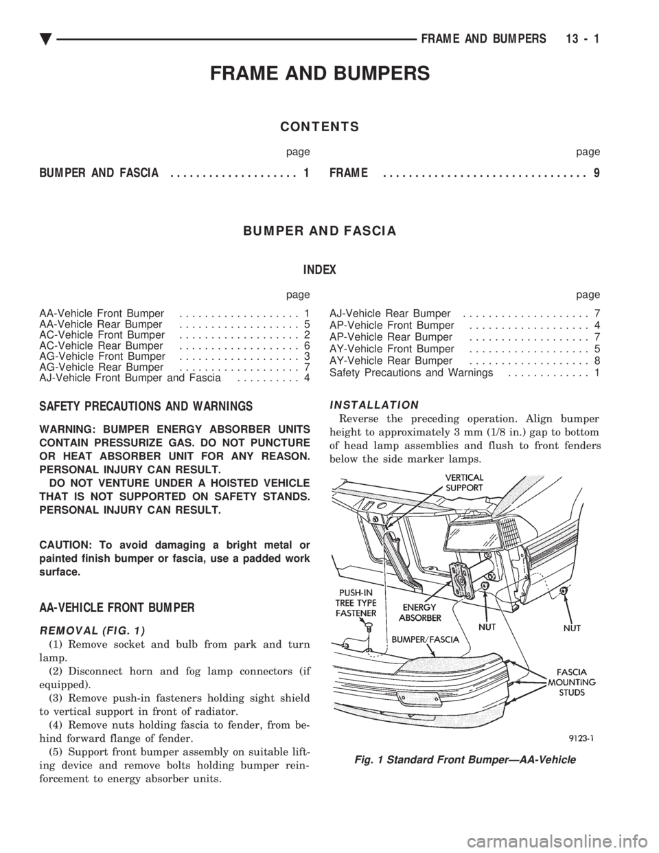
Fig. 1 Standard Front BumperÐAA-Vehicle
Ä FRAME AND BUMPERS 13 - 1
Page 1731 of 2438
FRAME INDEX
page page
Crossmember ........................... 17
Frame Dimensions ........................ 9 General Information
........................ 9
GENERAL INFORMATION
In this section, references are made to Vehicle
Family (Body) codes. To determine the vehicle family
identification code, refer to the Introduction Group at
the front of this manual.
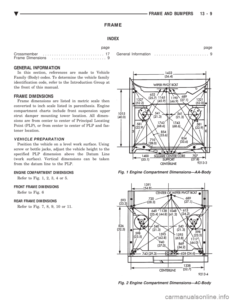
FRAME DIMENSIONS
Frame dimensions are listed in metric scale then
converted to inch scale listed in parenthesis. Engine
compartment charts include front suspension upper
strut damper mounting tower location. All dimen-
sions are from center to center of Principal Locating
Point (PLP), or from center to center of PLP and fas-
tener location.
VEHICLE PREPARATION
Position the vehicle on a level work surface. Using
screw or bottle jacks, adjust the vehicle height to the
specified PLP dimension above the Datum Line
(work surface). Vertical dimensions can be taken
from the datum line to the PLP.
ENGINE COMPARTMENT DIMENSIONS Refer to Fig. 1, 2, 3, 4 or 5.
FRONT FRAME DIMENSIONS Refer to Fig. 6
REAR FRAME DIMENSIONS Refer to Fig. 7, 8, 9, 10 or 11.
Fig. 1 Engine Compartment DimensionsÐAA-Body
Fig. 2 Engine Compartment DimensionsÐAC-Body
Ä FRAME AND BUMPERS 13 - 9