1993 CHEVROLET PLYMOUTH ACCLAIM light
[x] Cancel search: lightPage 2159 of 2438
gage compartment. If light is visible through a nor-
mally sealed location, water could enter through the
opening.
PRESSURIZED LEAK TEST METHOD
When a water leak into the passenger compartment
can not be detected by water testing, pressurize the
passenger compartment and soap test exterior of the
vehicle. To pressurize the passenger compartment,
close all doors and windows, start engine, and set
heater control to high blower in HEAT position. If
engine can not be started, connect a charger to the
battery to assure adequate voltage to the blower. With
interior pressurized, apply dish detergent solution to
suspected leak area on the exterior of the vehicle.
Apply detergent solution with spray device or soft
bristle brush. If soap bubbles occur at a body seam,
joint, seal or gasket the leak entry point could be at
that location.
WIND NOISE
Wind noise is the result of most air leaks. Air leaks
can be caused by poor sealing, improper body compo-
nent alignment, body seam porosity, or missing plugs
in the engine compartment or door hinge pillar areas.
All body sealing points should be air tight in normal
driving conditions. Moving sealing surfaces will not
always seal air tight under all conditions. At times,
side glass, door, or convertible top seals will allow wind
noise to be noticed in the passenger compartment
during high cross-winds. Over compensating on door,
glass, or top adjustments to stop wind noise that occurs
under severe conditions, can cause premature seal
wear and excessive closing or latching effort. After a repair procedure has been performed, test vehicle to
verify leak has stopped before returning vehicle to use. Wind noise can also be caused by improperly fitted
exterior mouldings or body ornamentation. Loose
mouldings can flutter, creating a buzzing or chattering
noise. An open cavity or protruding edge can create
whistling or howling noise. Inspect the exterior of the
vehicle to verify that these conditions do not exist.
VISUAL INSPECTION BEFORE TESTS
Verify that floor and body plugs are in place, body
drains are clear and body components are aligned and
sealed. If component alignment or sealing is necessary,
refer to the appropriate section of this group for proper
procedures.
ROAD TESTING WIND NOISE
(1) Drive the vehicle to verify the general location of
the wind noise. (2) Apply 50 mm (2 in.) masking tape in 150 mm (6
in.) lengths along weatherstrips, weld seams or moul-
dings. After each length is applied drive vehicle. If
noise goes away after a piece of tape is applied, remove
tape, locate and repair defect.
POSSIBLE CAUSE OF WIND NOISE
² Mouldings standing away from body surface can
catch wind and whistle.
² Gaps in sealed areas behind overhanging body
flanges can cause wind rushing sounds.
² Misaligned movable components.
² Missing or improperly installed plugs in pillars.
² Weld burn through holes.
Ä BODY 23 - 3
Page 2160 of 2438
PAINT
INTRODUCTION
A paint code is provided on the body code plate
located in the engine compartment. Refer to the Intro-
duction section at the front of this manual for body code
plate description. The color names provided in the
Paint and Trim Code Description chart are the color
names used on most repair product containers. The
color names in the new vehicle ordering guides vary
depending on car line but use the same color code.
BASE COAT/CLEAR COAT FINISH
On most vehicles a two part paint application (base
coat/clear coat) is used. Color paint that is applied to
primer is called base coat. The clear coat protects the
base coat from ultra violet light and provides a durable
high gloss finish.
WET SANDING,BUFFING AND POLISHING
Minor acid etching, orange peel or smudging in clear
coat can be reduced with light wet sanding, hand
buffing and polishing. If the finish has been wet sanded
in the past, it can not be repeated. Wet sanding
operation should be performed by a trained automotive
painter.
CAUTION: Do not remove clear coat finish, if
equipped. Base coat paint must retain clear coat to
shine.
PAINTED SURFACE TOUCH-UP
When a painted metal surface has been scratched or
chipped, it should be touched-up as soon as possible to avoid corrosion. For best results, use Mopar
tScratch
Filler/Primer, Touch-Up Paints and Clear Top Coat.
Refer to Introduction group of this manual for Body
Code Plate information.
TOUCH-UP PROCEDURE
(1) Scrape loose paint and corrosion from inside
scratch or chip. (2) Clean affected area with Mopar tTar/Road Oil
Remover and allow to dry. (3) Fill the inside of the scratch or chip with a coat of
filler/primer. Do not overlap primer onto good surface
finish. The applicator brush should be wet enough to
puddle fill the defect without running. Do not stroke
brush applicator on body surface. Allow the filler/
primer to dry hard. (4) Cover the filler/primer with color touch-up paint.
Do not overlap touch-up color onto the original color
coat around the scratch or chip. Butt the new color to
the original color if possible. Do not stroke applicator
brush on body surface. Allow touch-up paint to dry
hard. (5) On vehicles without clear coat, the touch-up color
can be lightly (600 grit) wet sanded and polished with
rubbing compound. (6) On vehicles with clear coat, Apply clear top coat
to touch-up paint with the same technique as described
in step 4. Allow clear top coat to dry hard. If desired,
step 5 can be performed on clear top coat.
23 - 4 BODY Ä
Page 2190 of 2438
bottom trunk lid to hinge attaching bolts. Separate
the trunk lid from the vehicle.
INSTALLATION
Reverse the preceding operation.
TRUNK LID HINGE
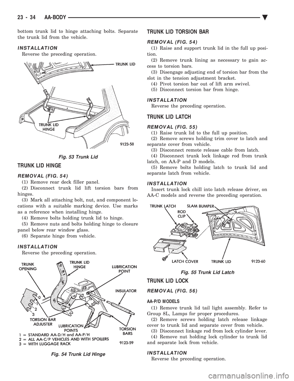
REMOVAL (FIG. 54)
(1) Remove rear deck filler panel.
(2) Disconnect trunk lid lift torsion bars from
hinges. (3) Mark all attaching bolt, nut, and component lo-
cations with a suitable marking device. Use marks
as a reference when installing hinge. (4) Remove bolts holding trunk lid to hinge.
(5) Remove nuts and bolts holding hinge to closure
panel below rear window glass. (6) Separate hinge from vehicle.
INSTALLATION
Reverse the preceding operation.
TRUNK LID TORSION BAR
REMOVAL (FIG. 54)
(1) Raise and support trunk lid in the full up posi-
tion. (2) Remove trunk lining as necessary to gain ac-
cess to torsion bars. (3) Disengage adjusting end of torsion bar from the
slot in the tension adjustment bracket. (4) Pivot torsion bar out of lift arm swivel.
(5) Disconnect torsion bar from hinge.
INSTALLATION
Reverse the preceding operation.
TRUNK LID LATCH
REMOVAL (FIG. 55)
(1) Raise trunk lid to the full up position.
(2) Remove screws holding trim cover to latch and
separate cover from vehicle. (3) Disconnect remote release cable from latch.
(4) Disconnect trunk lock linkage rod from trunk
latch, on AA-P and D models. (5) Remove bolts holding latch to trunk lid and
separate latch from vehicle.
INSTALLATION
Insert trunk lock chill into latch release driver, on
AA-C models and reverse the preceding operation.
TRUNK LID LOCK
REMOVAL (FIG. 56)
AA-P/D MODELS
(1) Remove trunk lid tail light assembly. Refer to
Group 8L, Lamps for proper procedures. (2) Remove screws holding latch release linkage
cover to trunk lid and separate cover from vehicle. (3) Disconnect linkage rod from lock cylinder lever.
(4) Remove nut holding lock cylinder to trunk lid
and separate lock from vehicle.
INSTALLATION
Reverse the preceding operation.
Fig. 53 Trunk Lid
Fig. 54 Trunk Lid Hinge
Fig. 55 Trunk Lid Latch
23 - 34 AA-BODY Ä
Page 2191 of 2438
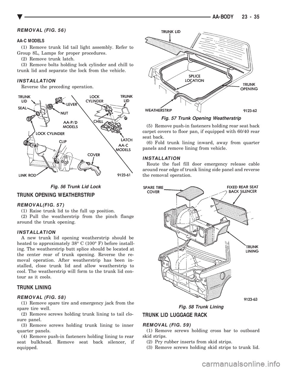
REMOVAL (FIG. 56)
AA-C MODELS (1) Remove trunk lid tail light assembly. Refer to
Group 8L, Lamps for proper procedures. (2) Remove trunk latch.
(3) Remove bolts holding lock cylinder and chill to
trunk lid and separate the lock from the vehicle.
INSTALLATION
Reverse the preceding operation.
TRUNK OPENING WEATHERSTRIP
REMOVAL(FIG. 57)
(1) Raise trunk lid to the full up position.
(2) Pull the weatherstrip from the pinch flange
around the trunk opening.
INSTALLATION
A new trunk lid opening weatherstrip should be
heated to approximately 38É C (100É F) before install-
ing. The weatherstrip butt splice should be located at
the center rear of trunk opening. Reverse the re-
moval operation. After weatherstrip has been in-
stalled, close trunk lid and allow weatherstrip to
cool. The weatherstrip will form to the trunk lid con-
tour as it cools.
TRUNK LINING
REMOVAL (FIG. 58)
(1) Remove spare tire and emergency jack from the
spare tire well. (2) Remove screws holding trunk lining to tail clo-
sure panel. (3) Remove screws holding trunk lining to inner
quarter panels. (4) Remove push-in fasteners holding lining to rear
seat bulkhead. Remove seat back silencer, if
equipped. (5) Remove push-in fasteners holding rear seat back
carpet covers to floor pan, if equipped with 60/40 rear
seat back. (6) Fold trunk lining inward, away from quarter
panels and remove lining from vehicle.
INSTALLATION
Route the fuel fill door emergency release cable
around rear edge of trunk lining side panel and reverse
the removal operation.
TRUNK LID LUGGAGE RACK
REMOVAL (FIG. 59)
(1) Remove screws holding cross bar to outboard
skid strips. (2) Pry rubber inserts from skid strips.
(3) Remove screws holding skid strips to trunk lid.
Fig. 56 Trunk Lid Lock
Fig. 57 Trunk Opening Weatherstrip
Fig. 58 Trunk Lining
Ä AA-BODY 23 - 35
Page 2193 of 2438
AC-VEHICLE BODY COMPONENT SERVICE INDEX
page page
A-Pillar and Roof Rail Mouldings ............. 46
B-Pillar Trim Panel ....................... 46
Body Mouldings .......................... 49
Cowl Panel Trim and Scuff Plates ............ 46
Door Frame Trim Moulding ................. 41
Front Door and Hinge ..................... 41
Front Door Glass ........................ 43
Front Door Latch ......................... 42
Front Door Trim Panel .................... 40
Front Door Water Shield ................... 41
Front Door Window Regulator ............... 42
Front End Splash Shields .................. 40
Front Seat Belts ......................... 47
Front Seats ............................. 48
Grille AC/C Body ......................... 38
Grille AC/D or AC/C-H Body ................ 37
Grille Extension Moulding .................. 37
Grille Opening Panel AC/C-Body ............. 38
Grille Opening Panel AC/D and AC/C-H Body . . . 37
Head Lining ............................. 45
Hood and Hinges ........................ 38
Hood Latch and Release Cable .............. 39
Hood Latch Release Cable ................. 39 Hood Ornament AC/C
..................... 38
Outside Door Handle ...................... 42
Overhead Console ........................ 45
Quarter Trim Panel ....................... 46
Rear Deck Filler Panel .................... 49
Rear Door and Hinge ..................... 44
Rear Door Frame Trim Moulding ............. 43
Rear Door Glass ......................... 45
Rear Door Glass Lift Plate and Guide Bar ..... 45
Rear Door Latch ......................... 44
Rear Door Outside Handle ................. 44
Rear Door Silencer and Water Shield ......... 43
Rear Door Trim Panel ..................... 43
Rear Door Window Regulator ............... 45
Rear Seat Belts .......................... 47
Rear Seats ............................. 49
Rear Shelf Trim Panel ..................... 47
Rear Window Glass ...................... 50
Side View Mirror Trim Cover ................ 41
Trunk Lid .............................. 50
Trunk Lid Hinge ......................... 51
Trunk Lid Torsion Bar ..................... 51
Vinyl Roof Bonnet ........................ 49
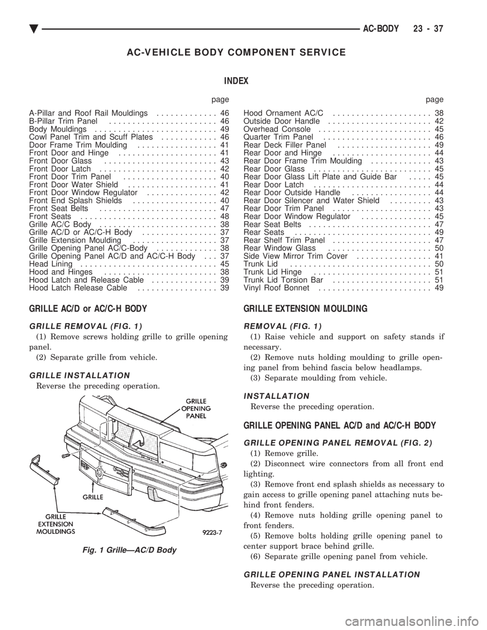
GRILLE AC/D or AC/C-H BODY
GRILLE REMOVAL (FIG. 1)
(1) Remove screws holding grille to grille opening
panel. (2) Separate grille from vehicle.
GRILLE INSTALLATION
Reverse the preceding operation.
GRILLE EXTENSION MOULDING
REMOVAL (FIG. 1)
(1) Raise vehicle and support on safety stands if
necessary. (2) Remove nuts holding moulding to grille open-
ing panel from behind fascia below headlamps. (3) Separate moulding from vehicle.
INSTALLATION
Reverse the preceding operation.
GRILLE OPENING PANEL AC/D and AC/C-H BODY
GRILLE OPENING PANEL REMOVAL (FIG. 2)
(1) Remove grille.
(2) Disconnect wire connectors from all front end
lighting. (3) Remove front end splash shields as necessary to
gain access to grille opening panel attaching nuts be-
hind front fenders. (4) Remove nuts holding grille opening panel to
front fenders. (5) Remove bolts holding grille opening panel to
center support brace behind grille. (6) Separate grille opening panel from vehicle.
GRILLE OPENING PANEL INSTALLATION
Reverse the preceding operation.
Fig. 1 GrilleÐAC/D Body
Ä AC-BODY 23 - 37
Page 2239 of 2438
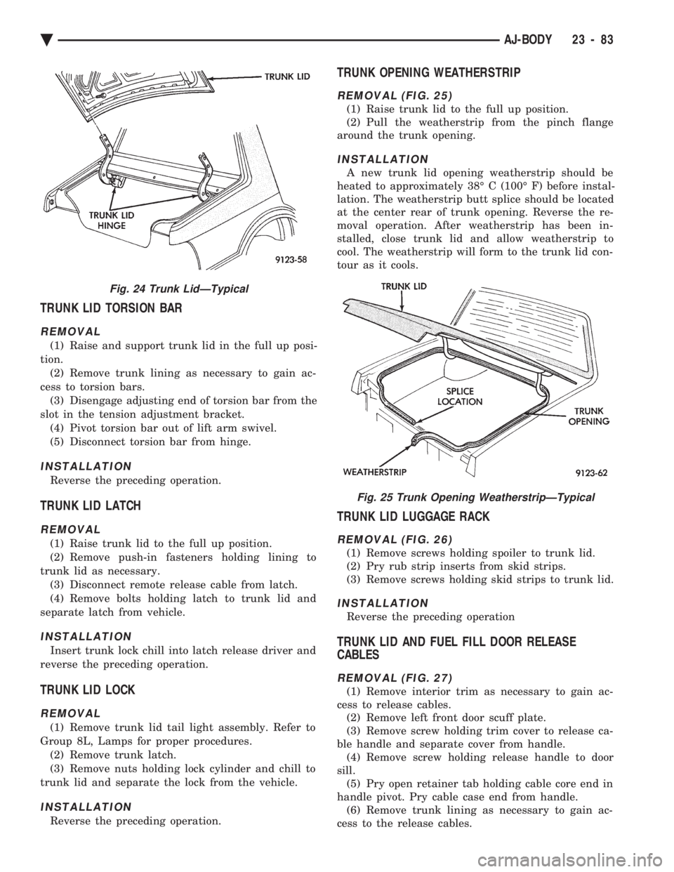
TRUNK LID TORSION BAR
REMOVAL
(1) Raise and support trunk lid in the full up posi-
tion. (2) Remove trunk lining as necessary to gain ac-
cess to torsion bars. (3) Disengage adjusting end of torsion bar from the
slot in the tension adjustment bracket. (4) Pivot torsion bar out of lift arm swivel.
(5) Disconnect torsion bar from hinge.
INSTALLATION
Reverse the preceding operation.
TRUNK LID LATCH
REMOVAL
(1) Raise trunk lid to the full up position.
(2) Remove push-in fasteners holding lining to
trunk lid as necessary. (3) Disconnect remote release cable from latch.
(4) Remove bolts holding latch to trunk lid and
separate latch from vehicle.
INSTALLATION
Insert trunk lock chill into latch release driver and
reverse the preceding operation.
TRUNK LID LOCK
REMOVAL
(1) Remove trunk lid tail light assembly. Refer to
Group 8L, Lamps for proper procedures. (2) Remove trunk latch.
(3) Remove nuts holding lock cylinder and chill to
trunk lid and separate the lock from the vehicle.
INSTALLATION
Reverse the preceding operation.
TRUNK OPENING WEATHERSTRIP
REMOVAL (FIG. 25)
(1) Raise trunk lid to the full up position.
(2) Pull the weatherstrip from the pinch flange
around the trunk opening.
INSTALLATION
A new trunk lid opening weatherstrip should be
heated to approximately 38É C (100É F) before instal-
lation. The weatherstrip butt splice should be located
at the center rear of trunk opening. Reverse the re-
moval operation. After weatherstrip has been in-
stalled, close trunk lid and allow weatherstrip to
cool. The weatherstrip will form to the trunk lid con-
tour as it cools.
TRUNK LID LUGGAGE RACK
REMOVAL (FIG. 26)
(1) Remove screws holding spoiler to trunk lid.
(2) Pry rub strip inserts from skid strips.
(3) Remove screws holding skid strips to trunk lid.
INSTALLATION
Reverse the preceding operation
TRUNK LID AND FUEL FILL DOOR RELEASE
CABLES
REMOVAL (FIG. 27)
(1) Remove interior trim as necessary to gain ac-
cess to release cables. (2) Remove left front door scuff plate.
(3) Remove screw holding trim cover to release ca-
ble handle and separate cover from handle. (4) Remove screw holding release handle to door
sill. (5) Pry open retainer tab holding cable core end in
handle pivot. Pry cable case end from handle. (6) Remove trunk lining as necessary to gain ac-
cess to the release cables.
Fig. 24 Trunk LidÐTypical
Fig. 25 Trunk Opening WeatherstripÐTypical
Ä AJ-BODY 23 - 83
Page 2275 of 2438
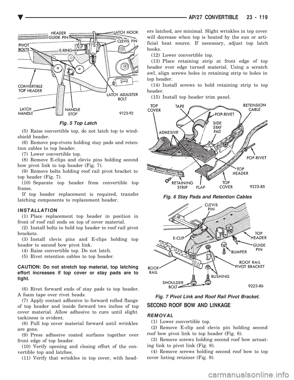
(5) Raise convertible top, do not latch top to wind-
shield header. (6) Remove pop-rivets holding stay pads and reten-
tion cables to top header. (7) Lower convertible top.
(8) Remove E-clips and clevis pins holding second
bow pivot link to top header (Fig. 7). (9) Remove bolts holding roof rail pivot bracket to
top header (Fig. 7). (10) Separate top header from convertible top
frame. If top header replacement is required, transfer
latching components to replacement header.
INSTALLATION
(1) Place replacement top header in position in
front of roof rail ends on top of cover material. (2) Install bolts to hold top header to roof rail pivot
brackets. (3) Install clevis pins and E-clips holding top
header to second bow pivot link. (4) Raise convertible top. Do not latch.
(5) Rivet retention cables to top header.
CAUTION: Do not stretch top material, top latching
effort increases if top cover or stay pads are to
tight.
(6) Rivet forward ends of stay pads to top header.
A foam tape over rivet heads. (7) Apply contact adhesive to forward rolled flange
of top header and inside forward two inches of top
cover material. Allow adhesive to cure until slight
tackiness is evident. (8) Pull top cover material forward until wrinkles
are gone. (9) Press adhesive coated surfaces together over
front edge of top header. (10) Verify opening and closing effort of the con-
vertible top and latches. (11) Verify that wrinkles in top cover, with head- ers latched, are minimal. Slight wrinkles in top cover
will decrease when top is heated by the sun or arti-
ficial heat source. If necessary, adjust top latch
hooks.
(12) Lower convertible top.
(13) Place retaining strip at front edge of top
header over edge turned material. Using a scratch
awl, align screws holes in retaining strip to holes in
top header. (14) Install screws to hold retaining strip to top
header. (15) Install top header trim panel.
SECOND ROOF BOW AND LINKAGE
REMOVAL
(1) Lower convertible top.
(2) Remove E-clip and clevis pin holding second
roof bow pivot link to top header (Fig. 8). (3) Remove screws holding second roof bow actuat-
ing link to pivot link (Fig. 8). (4) Remove screws holding second roof bow to top
cover listing retainer (Fig. 9).
Fig. 5 Top Latch
Fig. 6 Stay Pads and Retention Cables
Fig. 7 Pivot Link and Roof Rail Pivot Bracket.
Ä AP/27 CONVERTIBLE 23 - 119
Page 2295 of 2438
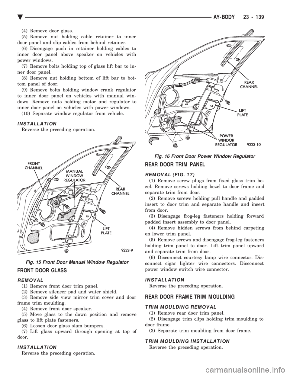
(4) Remove door glass.
(5) Remove nut holding cable retainer to inner
door panel and slip cables from behind retainer. (6) Disengage push in retainer holding cables to
inner door panel above speaker on vehicles with
power windows. (7) Remove bolts holding top of glass lift bar to in-
ner door panel. (8) Remove nut holding bottom of lift bar to bot-
tom panel of door. (9) Remove bolts holding window crank regulator
to inner door panel on vehicles with manual win-
dows. Remove nuts holding motor and regulator to
inner door panel on vehicles with power windows. (10) Separate window regulator from vehicle.
INSTALLATION
Reverse the preceding operation.
FRONT DOOR GLASS
REMOVAL
(1) Remove front door trim panel.
(2) Remove silencer pad and water shield.
(3) Remove side view mirror trim cover and door
frame trim moulding. (4) Remove front door speaker.
(5) Move glass to the down position and remove
glass to lift plate fasteners. (6) Loosen door glass slam bumpers.
(7) Lift glass upward through opening at top of
door.
INSTALLATION
Reverse the preceding operation.
REAR DOOR TRIM PANEL
REMOVAL (FIG. 17)
(1) Remove screw plugs from fixed glass trim be-
zel. Remove screws holding bezel to door frame and
separate trim from door. (2) Remove screws holding pull handle and padded
insert to door trim and separate handle and insert
from door. (3) Disengage frog-leg fasteners holding forward
padded insert assembly to door panel. (4) Remove hidden screws from behind carpeting
on lower trim panel. (5) Remove screws and disengage frog-leg fasteners
holding trim panel to door. Lift trim panel upward
and separate trim from door. (6) Disconnect courtesy lamp wire connector. Dis-
connect cigar lighter wire connectors. Disconnect
power window switch wire connector.
INSTALLATION
Reverse the preceding operation.
REAR DOOR FRAME TRIM MOULDING
TRIM MOULDING REMOVAL
(1) Remove rear door trim panel.
(2) Disengage trim clips holding trim moulding to
door frame. (3) Separate trim moulding from door frame.
TRIM MOULDING INSTALLATION
Reverse the preceding operation.
Fig. 15 Front Door Manual Window Regulator
Fig. 16 Front Door Power Window Regulator
Ä AY-BODY 23 - 139