1993 CHEVROLET PLYMOUTH ACCLAIM light
[x] Cancel search: lightPage 2017 of 2438
All subassemblies should be inspected and/or recon-
ditioned when transaxle recondition is performed. Re-
fer to appropriate subassembly in this section for
recondition procedure.
ASSEMBLY SUBASSEMBLY INSTALLATION
When rebuilding, reverse the above procedure.
VALVE BODY-RECONDITION
Tighten all valve body screws to 5 Newton-
meters (40 in.lbs.) Do not clamp any portion of valve body or transfer
plate in a vise. Any slight distortion of the aluminum
body or transfer plate will result in sticking valves,
excessive leakage or both. When removing or in-
stalling valves or plugs, slide them in or out
carefully. Do not use force. TAG ALL SPRINGS AS THEY ARE REMOVED
FOR REASSEMBLY IDENTIFICATION.
CLEANING AND INSPECTION
Allow all parts to soak a few minutes in a suitable
clean solvent. Wash thoroughly and blow dry with
compressed air. Make sure all passages are clean and
free from obstructions. Inspect manual and throttle valve operating levers
and shafts for being bent, worn or loose. If a lever is
loose on its shaft, it should be replaced. Do not attempt
to straighten bent levers. Inspect all mating surfaces for burrs, nicks and
scratches. Minor blemishes may be removed with cro-
cus cloth, using only a very light pressure. Using a
straightedge, inspect all mating surfaces for warpage
or distortion. Slight distortion may be corrected, using
a surface plate. Make sure all metering holes in steel
plate are open. Using a pen light, inspect bores in valve
body for scores, scratches, pits and irregularities. Inspect all valve springs for distortion and col-
lapsed coils. Inspect all valves and plugs for burrs,
nicks, and scores. Small nicks and scores may be re-
moved with crocus cloth, providing extreme care is
taken not to round off sharp edges. The sharpness of
these edges is important. They prevent foreign mat-
ter from lodging between valve and valve body, thus
reducing possibility of sticking. Inspect all valves
and plugs for freedom of operation in valve body
bores. When bores, valves, and plugs are clean and dry,
the valves and plugs should fall freely in the bores.
The valve body bores do not change dimensions with
use. Therefore, a valve body that was functioning
properly when vehicle was new, will operate cor-
rectly if it is properly and thoroughly cleaned. There
is no need to replace valve body unless it is damaged
in handling.
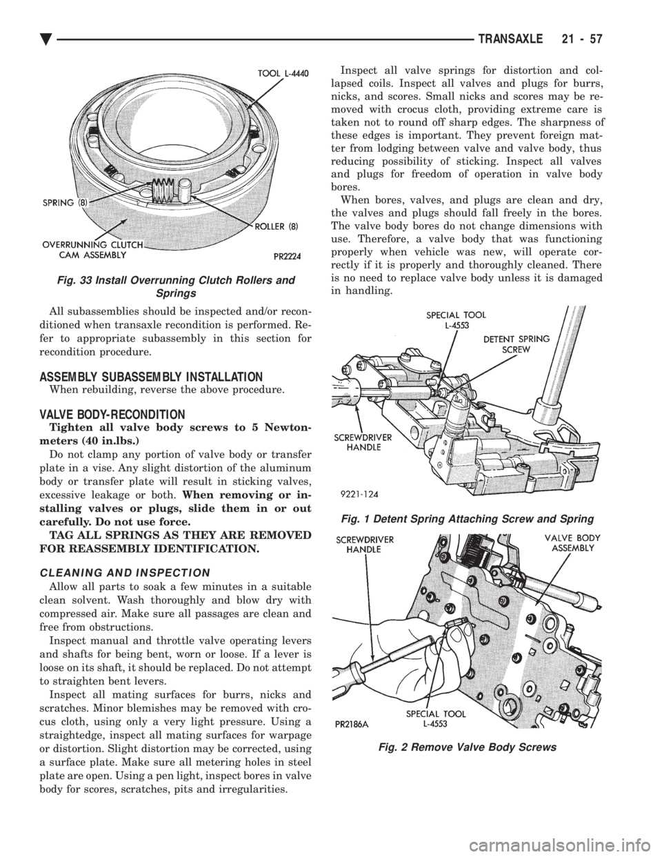
Fig. 1 Detent Spring Attaching Screw and Spring
Fig. 2 Remove Valve Body Screws
Fig. 33 Install Overrunning Clutch Rollers and Springs
Ä TRANSAXLE 21 - 57
Page 2022 of 2438
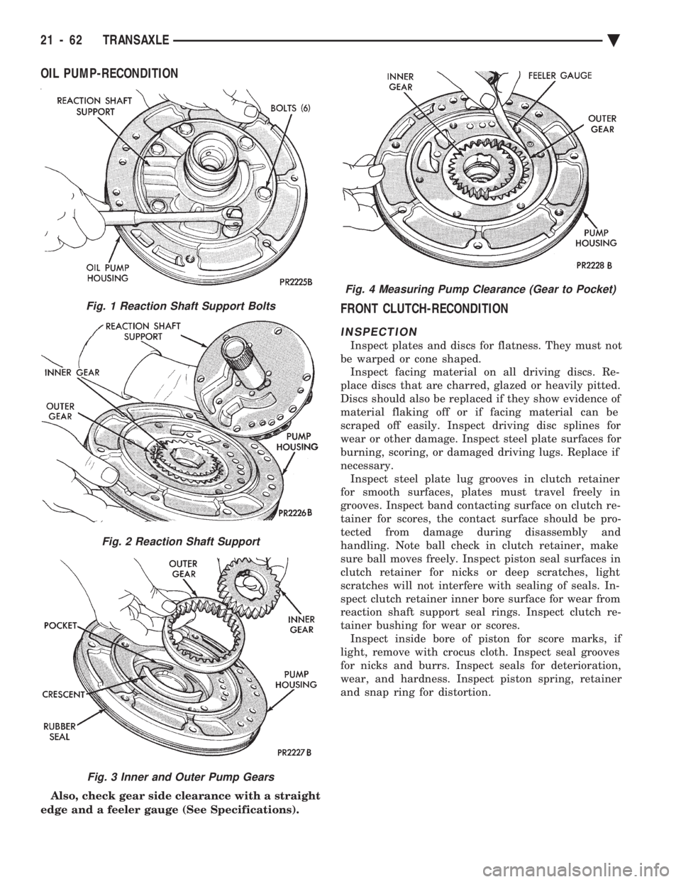
OIL PUMP-RECONDITION
Also, check gear side clearance with a straight
edge and a feeler gauge (See Specifications).
FRONT CLUTCH-RECONDITION
INSPECTION
Inspect plates and discs for flatness. They must not
be warped or cone shaped. Inspect facing material on all driving discs. Re-
place discs that are charred, glazed or heavily pitted.
Discs should also be replaced if they show evidence of
material flaking off or if facing material can be
scraped off easily. Inspect driving disc splines for
wear or other damage. Inspect steel plate surfaces for
burning, scoring, or damaged driving lugs. Replace if
necessary. Inspect steel plate lug grooves in clutch retainer
for smooth surfaces, plates must travel freely in
grooves. Inspect band contacting surface on clutch re-
tainer for scores, the contact surface should be pro-
tected from damage during disassembly and
handling. Note ball check in clutch retainer, make
sure ball moves freely. Inspect piston seal surfaces in
clutch retainer for nicks or deep scratches, light
scratches will not interfere with sealing of seals. In-
spect clutch retainer inner bore surface for wear from
reaction shaft support seal rings. Inspect clutch re-
tainer bushing for wear or scores. Inspect inside bore of piston for score marks, if
light, remove with crocus cloth. Inspect seal grooves
for nicks and burrs. Inspect seals for deterioration,
wear, and hardness. Inspect piston spring, retainer
and snap ring for distortion.
Fig. 4 Measuring Pump Clearance (Gear to Pocket)
Fig. 1 Reaction Shaft Support Bolts
Fig. 2 Reaction Shaft Support
Fig. 3 Inner and Outer Pump Gears
21 - 62 TRANSAXLE Ä
Page 2024 of 2438
REAR CLUTCH-RECONDITION
INSPECTION
Inspect facing material on all driving discs. Re-
place discs that are charred, glazed or heavily pitted.
Discs should also be replaced if they show evidence of
material flaking off or if facing material can be
scraped off easily. Inspect driving disc splines for
wear or other damage. Inspect steel plate and pres-
sure plate surface for burning, scoring or damaged
driving lugs. Re place if necessary. Inspect plates and
discs for flatness, they must not be warped or cone-
shaped. Inspect steel plate lug grooves in clutch retainer
for smooth surfaces, plates must travel freely in the
grooves. Note ball check in piston; make sure ball
moves freely. Inspect seal rings surfaces in clutch re-
tainer for nicks or deep scratches; light scratches will
not interfere with sealing of the seals. Inspect neo-
prene seal rings for deterioration, wear and hard-
ness. Inspect piston spring and waved snap ring for
distortion or breakage. Inspect teflon and/or cast iron seal rings on input
shaft for wear. Do not remove rings unless conditions
warrant. Inspect rear clutch to front clutch No. 2
thrust washer for wear. Washer thickness should be
.061 to .063 inch, replace if necessary.
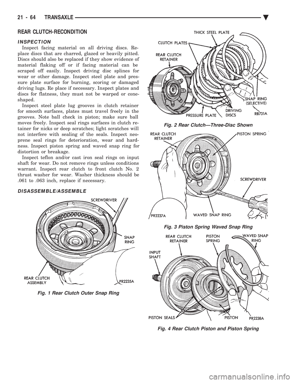
DISASSEMBLE/ASSEMBLE
Fig. 1 Rear Clutch Outer Snap Ring
Fig. 2 Rear ClutchÐThree-Disc Shown
Fig. 3 Piston Spring Waved Snap Ring
Fig. 4 Rear Clutch Piston and Piston Spring
21 - 64 TRANSAXLE Ä
Page 2048 of 2438
ing to each new reading. This provides the precise
and sophisticated friction element control needed to
make smooth clutch-to-clutch shifts for all gear
changes. The use of overrunning clutches or other
shift quality aids are not required. As with most au-
tomatic transaxles, all shifts involve releasing one el-
ement and applying a different element. In simplified
terms, the upshift logic allows the releasing element
to slip back wards slightly to ensure that it does not
have excess capacity; the apply element is filled until
it begins to make the speed change to the higher
gear; its apply pressure is then controlled to main-
tain the desired rate of speed change until the shift
is complete. The key to providing excellent shift
quality is precision; for example, as mentioned, the
release element for upshifts is allowed to slip back-
wards slightly; the amount of that slip is typically
less than a total of 20 degrees. To achieve that pre-
cision, the transmission control module learns the
characteristics of the particular transaxle that it is
controlling. It learns the release rate of the releasing
element and the apply time of the applying element.
It also learns the rate at which the apply element
builds pressure sufficient to begin making the speed
change. This method achieves more precision than
would be possible with exacting tolerances. It can
also adapt to any changes that occur with age or en-
vironment, for example, altitude, temperature, en-
gine output, etc. For kickdown shifts, the control logic allows the re-
leasing element to slip and then controls the rate at
which the input (and engine) accelerate; when the
lower gear speed is achieved, the releasing element
reapplies to maintain that speed until the apply ele-
ment is filled. This provides quick response since the
engine begins to accelerate immediately and a
smooth torque exchange since the release element
can control the rate of torque increase. This control
can make any powertrain feel more responsive with-
out in creasing harshness. Adaptive controls respond to input speed changes. They compensate for changes in engine or friction el-
ement torque and provide good, consistent shift qual-
ity for the life of the transaxle.
ON-BOARD DIAGNOSTICS
These controls provide comprehensive, on-board
transaxle diagnostics. The information available can
aid in transaxle diagnosis. For example, apply ele-
ment buildup rate indicates solenoid performance.
Also included are self diagnostic functions. Self diag-
nostics allow the technician to test the condition of
the electronic controls. The transmission control
module continuously monitors its critical functions.
It also records any malfunctions, and the number of
engine starts since the last malfunction. This allows
the technician to use the information in the event of
a customer complaint.
41TE TRANSAXLE GENERAL DIAGNOSIS
CAUTION: Before attempting any repair on a 41TE
four speed automatic transaxle, check for diagnos-
tic trouble codes with the DRB II scan tool. Always
use the Powertrain Diagnostic Test Procedure Man-
ual.
Transaxle malfunctions may be caused by these
general conditions:
² Poor engine performance
² Improper adjustments
² Hydraulic malfunctions
² Mechanical malfunctions
² Electronic malfunctions
Diagnosis of these problems should always begin
by checking the easily accessible variables: fluid
level and condition, gearshift cable adjustment. Then
perform a road test to determine if the problem has
been corrected or that more diagnosis is necessary. If
the problem exists after the preliminary tests and
corrections are completed, hydraulic pressure checks
should be performed.
21 - 88 TRANSAXLE Ä
Page 2063 of 2438
SPEED SENSOR-OUTPUT
CAUTION: When disconnecting speed sensor con-
nector, be sure that the weather seal does not fall
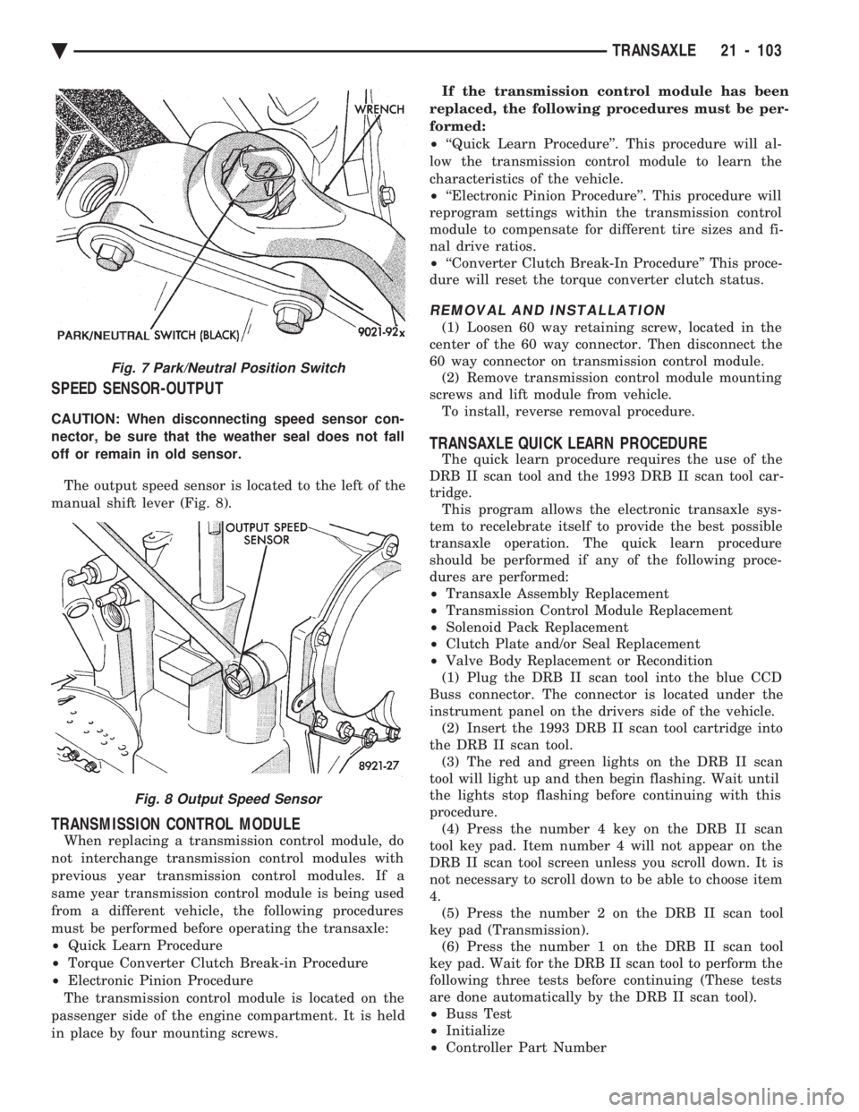
off or remain in old sensor. The output speed sensor is located to the left of the
manual shift lever (Fig. 8).
TRANSMISSION CONTROL MODULE
When replacing a transmission control module, do
not interchange transmission control modules with
previous year transmission control modules. If a
same year transmission control module is being used
from a different vehicle, the following procedures
must be performed before operating the transaxle:
² Quick Learn Procedure
² Torque Converter Clutch Break-in Procedure
² Electronic Pinion Procedure
The transmission control module is located on the
passenger side of the engine compartment. It is held
in place by four mounting screws. If the transmission control module has been
replaced, the following procedures must be per-
formed:
² ``Quick Learn Procedure''. This procedure will al-
low the transmission control module to learn the
characteristics of the vehicle.
² ``Electronic Pinion Procedure''. This procedure will
reprogram settings within the transmission control
module to compensate for different tire sizes and fi-
nal drive ratios.
² ``Converter Clutch Break-In Procedure'' This proce-
dure will reset the torque converter clutch status.
REMOVAL AND INSTALLATION
(1) Loosen 60 way retaining screw, located in the
center of the 60 way connector. Then disconnect the
60 way connector on transmission control module. (2) Remove transmission control module mounting
screws and lift module from vehicle. To install, reverse removal procedure.
TRANSAXLE QUICK LEARN PROCEDURE
The quick learn procedure requires the use of the
DRB II scan tool and the 1993 DRB II scan tool car-
tridge. This program allows the electronic transaxle sys-
tem to recelebrate itself to provide the best possible
transaxle operation. The quick learn procedure
should be performed if any of the following proce-
dures are performed:
² Transaxle Assembly Replacement
² Transmission Control Module Replacement
² Solenoid Pack Replacement
² Clutch Plate and/or Seal Replacement
² Valve Body Replacement or Recondition
(1) Plug the DRB II scan tool into the blue CCD
Buss connector. The connector is located under the
instrument panel on the drivers side of the vehicle. (2) Insert the 1993 DRB II scan tool cartridge into
the DRB II scan tool. (3) The red and green lights on the DRB II scan
tool will light up and then begin flashing. Wait until
the lights stop flashing before continuing with this
procedure. (4) Press the number 4 key on the DRB II scan
tool key pad. Item number 4 will not appear on the
DRB II scan tool screen unless you scroll down. It is
not necessary to scroll down to be able to choose item
4. (5) Press the number 2 on the DRB II scan tool
key pad (Transmission). (6) Press the number 1 on the DRB II scan tool
key pad. Wait for the DRB II scan tool to perform the
following three tests before continuing (These tests
are done automatically by the DRB II scan tool).
² Buss Test
² Initialize
² Controller Part Number
Fig. 7 Park/Neutral Position Switch
Fig. 8 Output Speed Sensor
Ä TRANSAXLE 21 - 103
Page 2064 of 2438
(7) Press the number 5 on the DRB II scan tool
key pad (Adjustments). (8) Press the number 3 on the DRB II scan tool
key pad (Quick Learn). Then follow the instructions
on the DRB II scan tool screen.
PINION FACTOR PROCEDURE
The vehicle speed readings for the speedometer are
taken from the output speed sensor. Because of dif-
ferent tire sizes and final drive ratios, the transmis-
sion control module must be calibrated to reflect the
different combinations of equipment. A procedure has
been developed called Pinion Factor. It allows the
technician to set the transmission control module ini-
tial setting so that the speedometer readings will be
correct. Failure to perform this procedure will cause a ``No
Speedometer Operation'' condition. This procedure must be performed if the transmis-
sion control module has been replaced. To properly read or reset the Pinion Factor, it is
necessary to use a DRB II scan tool. Perform the fol-
lowing steps with the DRB II scan tool to read or re-
set the Pinion Factor: (1) Plug the DRB II scan tool into the blue CCD
Bus connector. The connector is located under the in-
strument panel on the drivers side of the vehicle. (2) Insert the 1993 DRB II scan tool cartridge into
the DRB II scan tool. (3) The red and green lights on the DRB II scan
tool will light up and then begin flashing. Wait until
the lights stop flashing before continuing with this
procedure. (4) Press the number 4 key (Select System) on the
DRB II scan tool key pad. Item number 4 will not ap-
pear on the DRB II scan tool screen unless you scroll
down. It is not necessary to scroll down to be able to
choose item 4. (5) Press the number 2 on the DRB II scan tool
key pad (Transmission). (6) Press the number 1 on the DRB II scan tool
key pad. Wait for the DRB II scan tool to perform the
following three tests before continuing (These tests
are done automatically by the DRB II scan tool).
² Bus Test
² Initialize
² Transmission Control Module Part Number
(7) Press the number 5 on the DRB II scan tool
key pad (Adjustments). (8) Press the number 2 on the DRB II scan tool
key pad (Pinion Factor). Then follow the instructions
on the DRB II scan tool screen.
TORQUE CONVERTER CLUTCH BREAK-IN
PROCEDURE
A torque converter clutch break-in program is be-
ing used on all models with a 41TE. This program
will properly condition the torque converter clutch. This will eliminate shudder during partial torque
converter clutch operation on a new torque converter.
If the torque converter is replaced, the new clutch
within the torque converter will require break-in.
The current break-in status stored in the transmis-
sion control module will have to be reset to the start
of break-in with the DRB II scan tool. If a new transmission control module is put on the
vehicle, the status will be at the start of break-in.
This status is acceptable regardless of the mileage on
the torque converter. No modification of the break-in
status is required. To properly service these vehicles, it is necessary to
use a DRB II scan tool to read or reset the break-in
status. Perform the following steps with the DRB II
scan tool to reset the break-in status: (1) Plug the DRB II scan tool into the blue CCD
Bus connector. The connector is located under the in-
strument panel on the drivers side of the vehicle. (2) Insert the 1993 DRB II scan tool cartridge into
the DRB II scan tool. (3) The red and green lights on the DRB II scan
tool will light up and then begin flashing. Wait until
the lights stop flashing before continuing with this
procedure. (4) Press the number 4 key (Select System) on the
DRB II scan tool key pad. Item number 4 will not ap-
pear on the DRB II scan tool screen unless you scroll
down. It is not necessary to scroll down to be able to
choose item 4. (5) Press the number 2 on the DRB II scan tool
key pad (Transmission). (6) Press the number 1 on the DRB II scan tool
key pad. Wait for the DRB II scan tool to perform the
following three tests before continuing (These tests
are done automatically by the DRB II scan tool).
² Bus Test
² Initialize
² Transmission Control Module Part Number
(7) Press the number 5 on the DRB II scan tool
key pad (Adjustments). (8) Press the number 1 on the DRB II scan tool
key pad (Reset LU Clutch). The DRB II scan tool will
display one of three screens. (a) LU Clutch Break-in Status: Start
(b) LU Clutch Break-in Status: In-progress
Press ENTER to Reset Break-in status (c) LU Clutch Break-in Status: CompletePress
ENTER to Reset Break-in status
If screen (a) appears, the transmission control mod-
ule is at the beginning of its break-in program. No
further action is required. If screen (b) appears, the transmission control mod-
ule is in the middle of a its break-in program. Press
the enter key on the DRB II scan tool key pad to re-
turn the status to the start of break-in.
21 - 104 TRANSAXLE Ä
Page 2154 of 2438
WHEELS SERVICE PROCEDURES INDEX
page page
General Information ........................ 6
Tire and Wheel Balance .................... 6
Tire and Wheel Run Out .................... 7 Wheel Installation
......................... 6
Wheel Replacement ....................... 6
GENERAL INFORMATION
Original equipment wheels are designed for proper
operation at all loads up to the maximum vehicle ca-
pacity. All models use steel or cast aluminum drop center
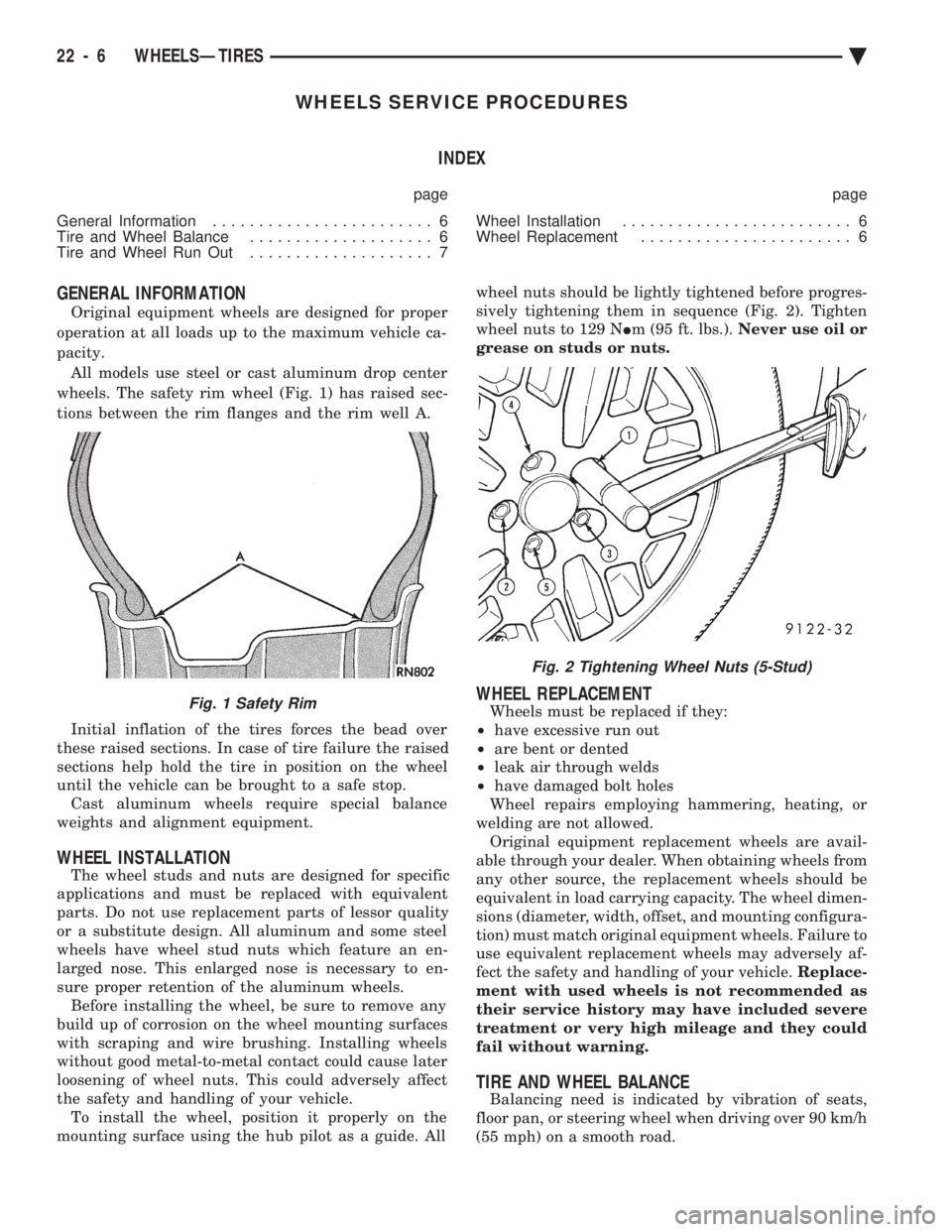
wheels. The safety rim wheel (Fig. 1) has raised sec-
tions between the rim flanges and the rim well A.
Initial inflation of the tires forces the bead over
these raised sections. In case of tire failure the raised
sections help hold the tire in position on the wheel
until the vehicle can be brought to a safe stop. Cast aluminum wheels require special balance
weights and alignment equipment.
WHEEL INSTALLATION
The wheel studs and nuts are designed for specific
applications and must be replaced with equivalent
parts. Do not use replacement parts of lessor quality
or a substitute design. All aluminum and some steel
wheels have wheel stud nuts which feature an en-
larged nose. This enlarged nose is necessary to en-
sure proper retention of the aluminum wheels. Before installing the wheel, be sure to remove any
build up of corrosion on the wheel mounting surfaces
with scraping and wire brushing. Installing wheels
without good metal-to-metal contact could cause later
loosening of wheel nuts. This could adversely affect
the safety and handling of your vehicle. To install the wheel, position it properly on the
mounting surface using the hub pilot as a guide. All wheel nuts should be lightly tightened before progres-
sively tightening them in sequence (Fig. 2). Tighten
wheel nuts to 129 N Im (95 ft. lbs.). Never use oil or
grease on studs or nuts.
WHEEL REPLACEMENT
Wheels must be replaced if they:
² have excessive run out
² are bent or dented
² leak air through welds
² have damaged bolt holes
Wheel repairs employing hammering, heating, or
welding are not allowed. Original equipment replacement wheels are avail-
able through your dealer. When obtaining wheels from
any other source, the replacement wheels should be
equivalent in load carrying capacity. The wheel dimen-
sions (diameter, width, offset, and mounting configura-
tion) must match original equipment wheels. Failure to
use equivalent replacement wheels may adversely af-
fect the safety and handling of your vehicle. Replace-
ment with used wheels is not recommended as
their service history may have included severe
treatment or very high mileage and they could
fail without warning.
TIRE AND WHEEL BALANCE
Balancing need is indicated by vibration of seats,
floor pan, or steering wheel when driving over 90 km/h
(55 mph) on a smooth road.
Fig. 1 Safety Rim
Fig. 2 Tightening Wheel Nuts (5-Stud)
22 - 6 WHEELSÐTIRES Ä
Page 2158 of 2438
BODY DIAGNOSTIC PROCEDURES INDEX
page page
Water Leaks ............................. 2 Wind Noise.............................. 3
WATER LEAKS
Water leaks can be caused by poor sealing, improper
body component alignment, body seam porosity, miss-
ing plugs, or blocked drain holes. Centrifugal and
gravitational force can cause water to drip from an
area somewhat distant from the actual leak point,
making leak detection difficult. All body sealing points
should be water tight in normal wet driving conditions.
Water flowing downward from the front of the vehicle
should not enter the passenger or luggage compart-
ment. Moving sealing surfaces will not always seal
water tight under all conditions. At times, side glass,
door, or convertible top seals will allow water to enter
the passenger compartment during high pressure
washing or hard driving rain (severe) conditions. Over
compensating on door, glass, or top adjustments to stop
a water leak that occurs under severe conditions, can
cause premature seal wear and excessive closing or
latching effort. After a repair procedure has been
performed, water test vehicle to verify leak has stopped
before returning vehicle to use.
VISUAL INSPECTION BEFORE WATER LEAK TESTS
Verify that floor and body plugs are in place, body
drains are clear and body components are aligned and
sealed. If component alignment or sealing is necessary,
refer to the appropriate section of this group for proper
procedures.
WATER LEAK TESTS
WARNING: DO NOT USE ELECTRIC SHOP LIGHTS
OR TOOLS IN WATER TEST AREA, PERSONAL IN-
JURY CAN RESULT.
When a determination has been made on the condi-
tions that a water leak occurs, simulate the conditions
as closely as possible.
² If a leak occurs when the car is parked in a steady
light rain, flood the leak area with a open ended garden
hose.
² If a leak occurs at highway speeds in a steady rain,
test the leak area with a stream or fan spray of water
from a garden hose with an adjustable nozzle. Direct
the spray in the direction comparable to actual condi-
tions. ²
If a leak seems to occur only when the vehicle is
parked on an incline, hoist the end or side of the vehicle
to simulate this condition before water testing. This
method can also be used when the leak occurs when the
vehicle accelerates, stops, or turns. If the leak occurs
on acceleration, hoist the front of the vehicle. If the
leak occurs when braking, hoist the back of the vehicle.
If the leak occurs on left turns, hoist the left side of the
vehicle. If the leak occurs on right turns, hoist the right
side of the vehicle. For hoisting recommendations refer
to Group 0, Lubrication and Maintenance, General
Information section.
WATER LEAK DETECTION
To detect a water leak point of entry, perform a water
test and watch for water tracks or droplets forming on
the inside if the vehicle. If necessary remove interior
trim covers or panels to gain visual access to the leak
area. If the hose can not be positioned without being
held, have someone help perform the water test. Some water leaks must be tested for a considerable
length of time to become apparent. When a leak ap-
pears, determine the highest point of the water track or
drop. The highest point usually will indicate the point
of entry. After leak point has been determined, repair
the leak and water test to verify that leak has stopped. Locating the entry point of water that is leaking into
a cavity between panels can be difficult. The trapped
water splashes or runs from the cavity it is dammed up
in, often at a distance from the entry point. Most water
leaks of this type become apparent after accelerating,
stopping, turning, or when on a incline.
MIRROR INSPECTION METHOD
When a leak point area is visually obstructed, use a
suitable mirror to gain visual access. A mirror can also
be used to deflect light to a limited access area to assist
in locating a leak point.
BRIGHT LIGHT LEAK TEST METHOD
Some water leaks in the luggage compartment can be
detected without water testing. Position the vehicle in
a brightly light area. From inside the darkened lug-
gage compartment inspect around seals and body
seams. If necessary, have a helper direct a drop light
over the suspected leak areas around the lug-
23 - 2 BODY Ä