1993 CHEVROLET PLYMOUTH ACCLAIM light
[x] Cancel search: lightPage 2361 of 2438
INSTALLATION
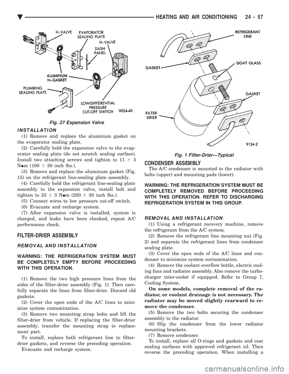
(1) Remove and replace the aluminum gasket on
the evaporator sealing plate. (2) Carefully hold the expansion valve to the evap-
orator sealing plate (do not scratch sealing surface).
Install two attaching screws and tighten to 11 63
N Im (100 630 inch lbs.).
(3) Remove and replace the aluminum gasket (Fig.
15) on the refrigerant line-sealing plate assembly. (4) Carefully hold the refrigerant line-sealing plate
assembly to the expansion valve, install bolt and
tighten to 23 63N Im (200 630 inch lbs.).
(5) Connect wires to low pressure cut-off switch.
(6) Evacuate and recharge system.
(7) After expansion valve is installed, system is
charged, and leaks have been checked, repeat A/C
performance check.
FILTER-DRIER ASSEMBLY
REMOVAL AND INSTALLATION
WARNING: THE REFRIGERATION SYSTEM MUST
BE COMPLETELY EMPTY BEFORE PROCEEDING
WITH THIS OPERATION.
(1) Remove the two high pressure lines from the
sides of the filter-drier assembly (Fig. 1). Then care-
fully separate the lines from filter-drier. Discard old
gaskets. (2) Cover the open ends of the A/C lines to mini-
mize system contamination. (3) Remove two mounting strap bolts and lift the
filter-drier from vehicle. If replacing the filter-drier
assembly, transfer the mounting strap to replace-
ment part. To install, replace both refrigerant line to filter-
drier gaskets, and reverse the preceding operation. Evacuate and recharge system.
CONDENSER ASSEMBLY
The A/C condenser is mounted to the radiator with
bolts (upper) and mounting pads (lower).
WARNING: THE REFRIGERATION SYSTEM MUST BE
COMPLETELY REMOVED BEFORE PROCEEDING
WITH THIS OPERATION. REFER TO DISCHARGING
REFRIGERATION SYSTEM IN THIS GROUP.
REMOVAL AND INSTALLATION
(1) Using a refrigerant recovery machine, remove
the refrigerant from the A/C system. (2) Remove the refrigerant line mounting nut (Fig.
2) and separate the refrigerant lines from condenser
sealing plate. (3) Cover the open ends of the A/C lines and con-
denser to minimize system contamination. (4) Remove the coolant overflow bottle, electric cool-
ing fans and radiator assembly. Also remove the turbo-
charger inter-cooler if equipped. Refer to Group 7,
Cooling System. On some models, complete removal of the ra-
diator, or coolant drainage is not necessary. The
radiator may be moved slightly rearward to re-
move the condenser. (5) Remove the two bolts securing the condenser
assembly to the radiator. (6) Slip the condenser from the lower radiator
mounting brackets. (7) Remove condenser.
To install, replace all O-rings and gaskets and coat
sealing surfaces with approved refrigerant oil. Then
reverse the preceding operation. When installing a
Fig. 27 Expansion Valve
Fig. 1 Filter-DrierÐTypical
Ä HEATING AND AIR CONDITIONING 24 - 57
Page 2366 of 2438
AA BODY PROCEDURE
WARNING: IF EQUIPPED WITH A/C, THE REFRIG-
ERATION SYSTEM MUST BE COMPLETELY EMPTY
BEFORE PROCEEDING WITH THIS OPERATION. Refer to Group 8E and Group 23 for component re-
moval and installation when performing this opera-
tion. (1) Perform steps 1 through 7 of Blower Motor re-
moval and installation. (2) Remove relay panel above glove compartment
opening. (3) Disconnect the A/C vacuum line connector and
radio noise capacitor connectors. (4) Remove left windshield pillar trim cover.
(5) Remove left lower side cowl trim cover.
(6) Remove hood release handle mechanism attach-
ing screws. (7) Remove steering column trim covers.
(8) Disconnect parking brake release mechanism
connecting rod. Gain access through fuse panel open-
ing. (9) Remove lower left instrument panel silencer.
(10) Remove lower left instrument panel reinforce-
ment. (11) Remove instrument panel center (radio) bezel.
(12) Remove forward floor console.
(13) Remove the radio.
(14) Remove the heater-A/C control.
(15) Remove cigar lighter.
(16) Remove message center/trip computer, if
equipped. (17) Disconnect side window demister tubes from
top of heat A/C unit. (18) Remove steering column upper attaching bolts
and allow the steering wheel to rest on the driver
seat cushion. (19) Remove upper instrument panel (defroster
outlet) cover. (20) Remove upper instrument panel attaching
screws from below the windshield opening. (21) Loosen (do not remove) the left lower cowl in-
strument panel attaching screw. (22) Remove the right lower cowl instrument panel
attaching screw.
CAUTION: Protect the passenger seat cover from
soiling or damage using a suitable cover.
(23) Carefully pull the right side of the instrument
panel away from the vehicle. Allow the instrument
panel to rest on the passenger seat cushion.
CAUTION: Before proceeding with the next opera-
tion, review the Safety Precautions and Warnings at
the front of this Group. (24) From the engine compartment, drain the cool-
ing system and disconnect the heater hoses from the
heater core nipples. Plug the nipples to avoid spilling
coolant inside the vehicle. (25) Disconnect the refrigerant lines from the ex-
pansion-valve at the dash panel on the right side of
the vehicle. Seal the refrigerant lines to prevent con-
tamination. (26) Remove the expansion valve from the evapo-
rator plate. Seal the valve to avoid contamination. (27) Remove the condensate drain tube.
(28) Remove heater-A/C unit to dash panel attach-
ing nuts. (29) From inside the vehicle, pull rearward on the
heater-A/C unit to clear the dash panel silencer and
remove the unit from the vehicle. To install, reverse the preceding operation. Refill
cooling system and test for leaks. Evacuate and
charge the refrigerant system and test overall perfor-
mance.
AG, AJ BODY PROCEDURE
WARNING: IF EQUIPPED WITH A/C, THE REFRIG-
ERATION SYSTEM MUST BE COMPLETELY EMPTY
BEFORE PROCEEDING WITH THIS OPERATION.
(1) Disconnect the battery negative cable.
(2) Drain the coolant from cooling system. Refer to
Group 7, Cooling System. (3) Remove the air conditioner expansion valve (if
equipped). (4) Disconnect the heater hoses from heater core.
Then plug or cap the tubes on heater core. This will
prevent spilling coolant into the interior of vehicle
during unit removal. (5) Remove the condensate drain tube.
(6) Disconnect the A/C-heater vacuum supply line
from vacuum supply nipple (in the engine compart-
ment). (7) Remove the four A/C-heater assembly-to-dash
panel attaching nuts. (8) Remove the passenger side front seat. Refer to
Group 23, Body. (9) Remove the kick panel/sill cover at right door
opening. (10) Remove the body computer (Fig. 6) located at
the lower right section of the right front door pillar. (11) Remove the glove box assembly. Refer to
Group 8E, Instrument Panel. (12) Remove the carpeted panels from both sides of
the console. (13) Un-clip the radio antenna cable from the
metal support (Fig. 6) located behind and below the
glove box opening. (14) Instrument panel removal is not necessary to
remove the A/C-heater assembly from the vehicle.
24 - 62 HEATING AND AIR CONDITIONING Ä
Page 2367 of 2438
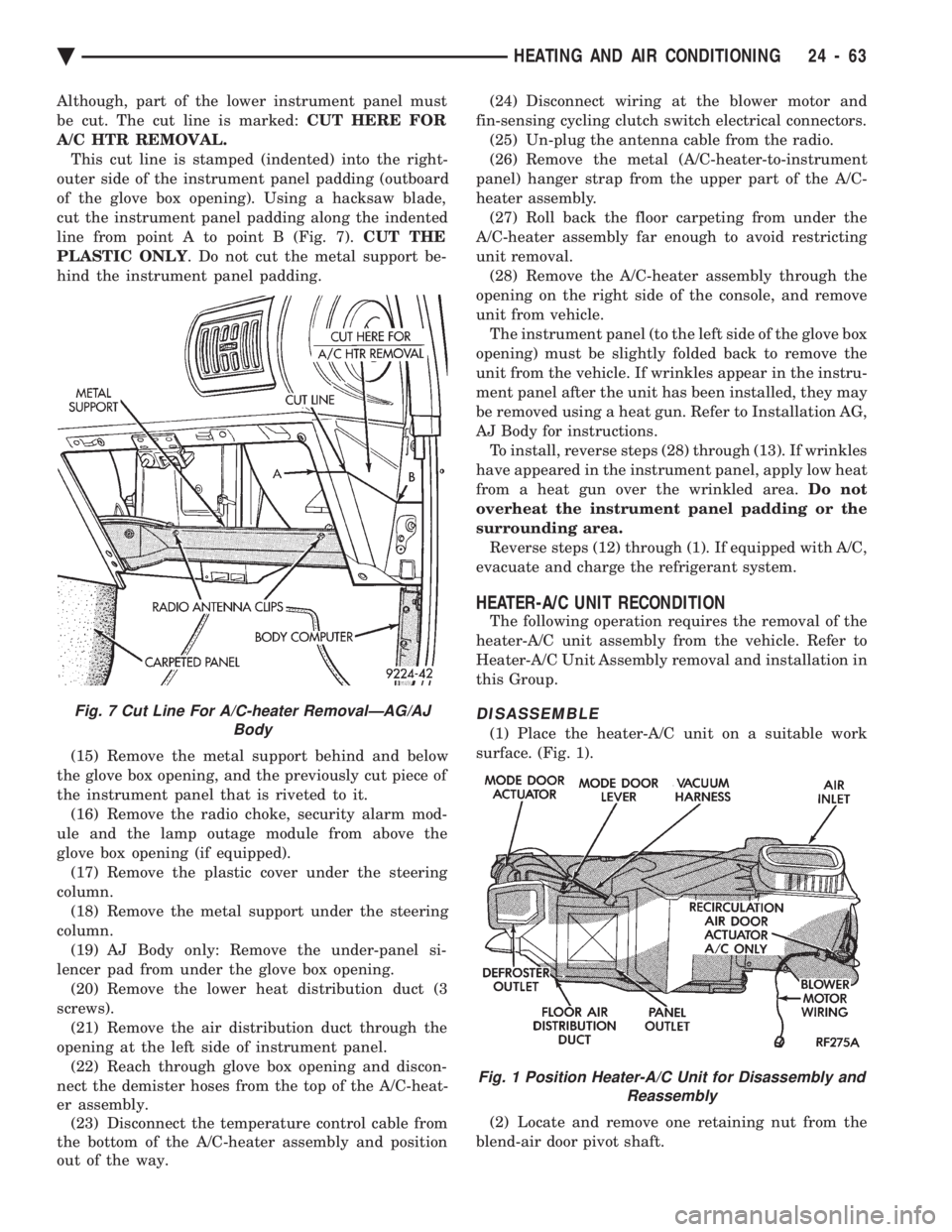
Although, part of the lower instrument panel must
be cut. The cut line is marked: CUT HERE FOR
A/C HTR REMOVAL. This cut line is stamped (indented) into the right-
outer side of the instrument panel padding (outboard
of the glove box opening). Using a hacksaw blade,
cut the instrument panel padding along the indented
line from point A to point B (Fig. 7). CUT THE
PLASTIC ONLY . Do not cut the metal support be-
hind the instrument panel padding.
(15) Remove the metal support behind and below
the glove box opening, and the previously cut piece of
the instrument panel that is riveted to it. (16) Remove the radio choke, security alarm mod-
ule and the lamp outage module from above the
glove box opening (if equipped). (17) Remove the plastic cover under the steering
column. (18) Remove the metal support under the steering
column. (19) AJ Body only: Remove the under-panel si-
lencer pad from under the glove box opening. (20) Remove the lower heat distribution duct (3
screws). (21) Remove the air distribution duct through the
opening at the left side of instrument panel. (22) Reach through glove box opening and discon-
nect the demister hoses from the top of the A/C-heat-
er assembly. (23) Disconnect the temperature control cable from
the bottom of the A/C-heater assembly and position
out of the way. (24) Disconnect wiring at the blower motor and
fin-sensing cycling clutch switch electrical connectors. (25) Un-plug the antenna cable from the radio.
(26) Remove the metal (A/C-heater-to-instrument
panel) hanger strap from the upper part of the A/C-
heater assembly. (27) Roll back the floor carpeting from under the
A/C-heater assembly far enough to avoid restricting
unit removal. (28) Remove the A/C-heater assembly through the
opening on the right side of the console, and remove
unit from vehicle. The instrument panel (to the left side of the glove box
opening) must be slightly folded back to remove the
unit from the vehicle. If wrinkles appear in the instru-
ment panel after the unit has been installed, they may
be removed using a heat gun. Refer to Installation AG,
AJ Body for instructions. To install, reverse steps (28) through (13). If wrinkles
have appeared in the instrument panel, apply low heat
from a heat gun over the wrinkled area. Do not
overheat the instrument panel padding or the
surrounding area. Reverse steps (12) through (1). If equipped with A/C,
evacuate and charge the refrigerant system.
HEATER-A/C UNIT RECONDITION
The following operation requires the removal of the
heater-A/C unit assembly from the vehicle. Refer to
Heater-A/C Unit Assembly removal and installation in
this Group.
DISASSEMBLE
(1) Place the heater-A/C unit on a suitable work
surface. (Fig. 1).
(2) Locate and remove one retaining nut from the
blend-air door pivot shaft.
Fig. 7 Cut Line For A/C-heater RemovalÐAG/AJ Body
Fig. 1 Position Heater-A/C Unit for Disassembly andReassembly
Ä HEATING AND AIR CONDITIONING 24 - 63
Page 2375 of 2438
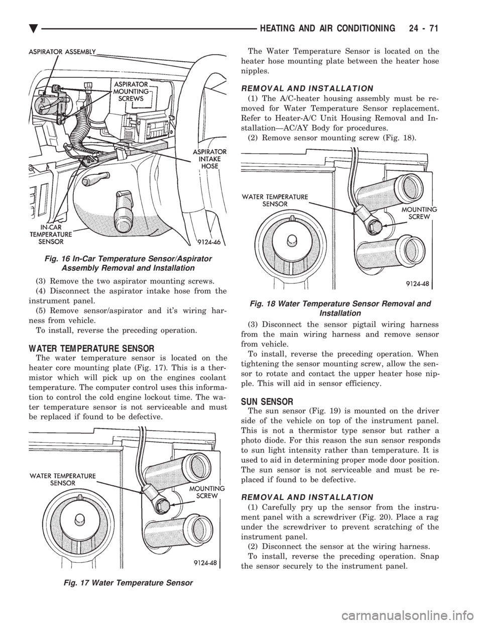
(3) Remove the two aspirator mounting screws.
(4) Disconnect the aspirator intake hose from the
instrument panel. (5) Remove sensor/aspirator and it's wiring har-
ness from vehicle. To install, reverse the preceding operation.
WATER TEMPERATURE SENSOR
The water temperature sensor is located on the
heater core mounting plate (Fig. 17). This is a ther-
mistor which will pick up on the engines coolant
temperature. The computer control uses this informa-
tion to control the cold engine lockout time. The wa-
ter temperature sensor is not serviceable and must
be replaced if found to be defective. The Water Temperature Sensor is located on the
heater hose mounting plate between the heater hose
nipples.
REMOVAL AND INSTALLATION
(1) The A/C-heater housing assembly must be re-
moved for Water Temperature Sensor replacement.
Refer to Heater-A/C Unit Housing Removal and In-
stallationÐAC/AY Body for procedures. (2) Remove sensor mounting screw (Fig. 18).
(3) Disconnect the sensor pigtail wiring harness
from the main wiring harness and remove sensor
from vehicle. To install, reverse the preceding operation. When
tightening the sensor mounting screw, allow the sen-
sor to rotate and contact the upper heater hose nip-
ple. This will aid in sensor efficiency.
SUN SENSOR
The sun sensor (Fig. 19) is mounted on the driver
side of the vehicle on top of the instrument panel.
This is not a thermistor type sensor but rather a
photo diode. For this reason the sun sensor responds
to sun light intensity rather than temperature. It is
used to aid in determining proper mode door position.
The sun sensor is not serviceable and must be re-
placed if found to be defective.
REMOVAL AND INSTALLATION
(1) Carefully pry up the sensor from the instru-
ment panel with a screwdriver (Fig. 20). Place a rag
under the screwdriver to prevent scratching of the
instrument panel. (2) Disconnect the sensor at the wiring harness.
To install, reverse the preceding operation. Snap
the sensor securely to the instrument panel.
Fig. 16 In-Car Temperature Sensor/Aspirator Assembly Removal and Installation
Fig. 17 Water Temperature Sensor
Fig. 18 Water Temperature Sensor Removal and Installation
Ä HEATING AND AIR CONDITIONING 24 - 71
Page 2409 of 2438
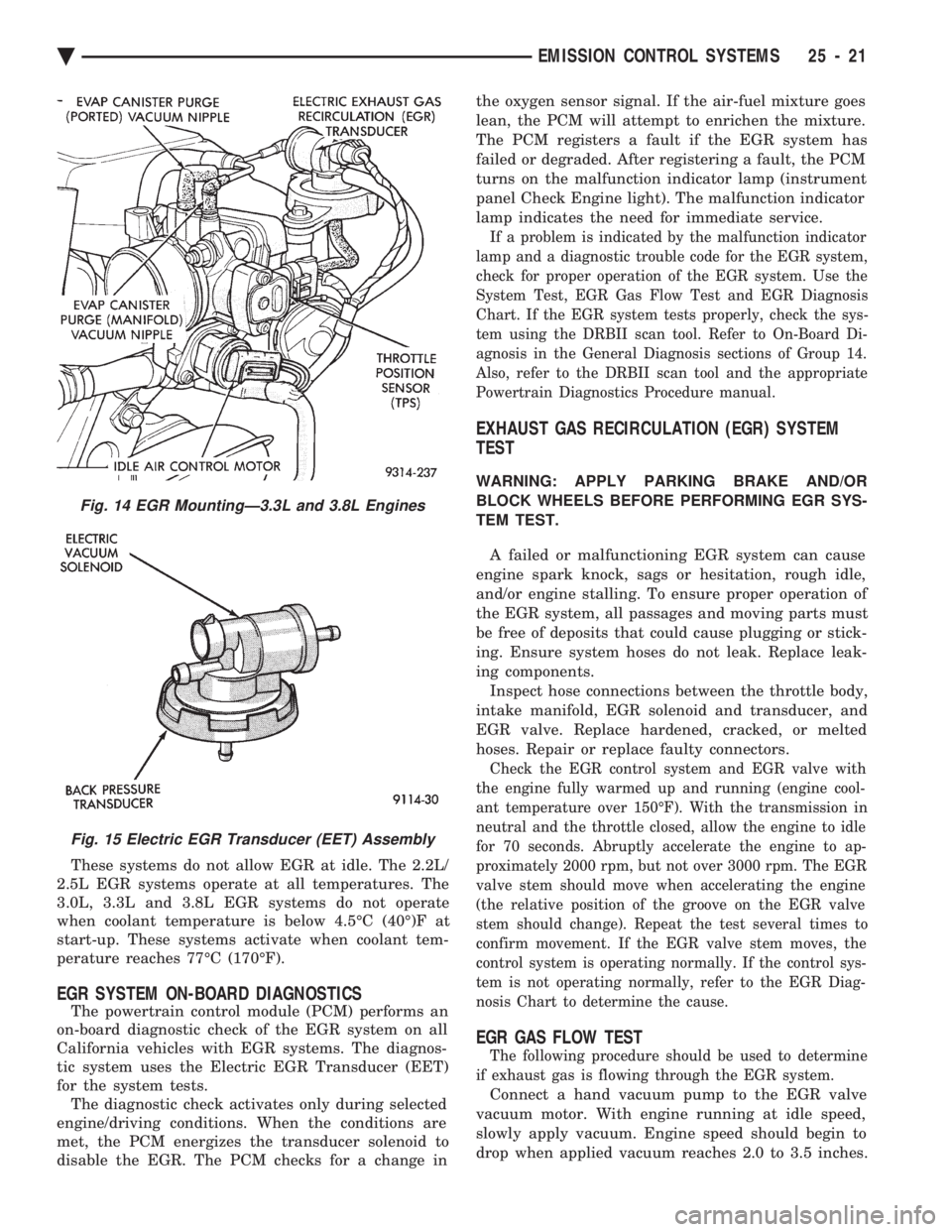
These systems do not allow EGR at idle. The 2.2L/
2.5L EGR systems operate at all temperatures. The
3.0L, 3.3L and 3.8L EGR systems do not operate
when coolant temperature is below 4.5ÉC (40É)F at
start-up. These systems activate when coolant tem-
perature reaches 77ÉC (170ÉF).
EGR SYSTEM ON-BOARD DIAGNOSTICS
The powertrain control module (PCM) performs an
on-board diagnostic check of the EGR system on all
California vehicles with EGR systems. The diagnos-
tic system uses the Electric EGR Transducer (EET)
for the system tests. The diagnostic check activates only during selected
engine/driving conditions. When the conditions are
met, the PCM energizes the transducer solenoid to
disable the EGR. The PCM checks for a change in the oxygen sensor signal. If the air-fuel mixture goes
lean, the PCM will attempt to enrichen the mixture.
The PCM registers a fault if the EGR system has
failed or degraded. After registering a fault, the PCM
turns on the malfunction indicator lamp (instrument
panel Check Engine light). The malfunction indicator
lamp indicates the need for immediate service.
If a problem is indicated by the malfunction indicator
lamp and a diagnostic trouble code for the EGR system,
check for proper operation of the EGR system. Use the
System Test, EGR Gas Flow Test and EGR Diagnosis
Chart. If the EGR system tests properly, check the sys-
tem using the DRBII scan tool. Refer to On-Board Di-
agnosis in the General Diagnosis sections of Group 14.
Also, refer to the DRBII scan tool and the appropriate
Powertrain Diagnostics Procedure manual.
EXHAUST GAS RECIRCULATION (EGR) SYSTEM
TEST
WARNING: APPLY PARKING BRAKE AND/OR
BLOCK WHEELS BEFORE PERFORMING EGR SYS-
TEM TEST.
A failed or malfunctioning EGR system can cause
engine spark knock, sags or hesitation, rough idle,
and/or engine stalling. To ensure proper operation of
the EGR system, all passages and moving parts must
be free of deposits that could cause plugging or stick-
ing. Ensure system hoses do not leak. Replace leak-
ing components. Inspect hose connections between the throttle body,
intake manifold, EGR solenoid and transducer, and
EGR valve. Replace hardened, cracked, or melted
hoses. Repair or replace faulty connectors.
Check the EGR control system and EGR valve with
the engine fully warmed up and running (engine cool-
ant temperature over 150ÉF). With the transmission in
neutral and the throttle closed, allow the engine to idle
for 70 seconds. Abruptly accelerate the engine to ap-
proximately 2000 rpm, but not over 3000 rpm. The EGR
valve stem should move when accelerating the engine
(the relative position of the groove on the EGR valve
stem should change). Repeat the test several times to
confirm movement. If the EGR valve stem moves, the
control system is operating normally. If the control sys-
tem is not operating normally, refer to the EGR Diag-
nosis Chart to determine the cause.
EGR GAS FLOW TEST
The following procedure should be used to determine
if exhaust gas is flowing through the EGR system.
Connect a hand vacuum pump to the EGR valve
vacuum motor. With engine running at idle speed,
slowly apply vacuum. Engine speed should begin to
drop when applied vacuum reaches 2.0 to 3.5 inches.
Fig. 14 EGR MountingÐ3.3L and 3.8L Engines
Fig. 15 Electric EGR Transducer (EET) Assembly
Ä EMISSION CONTROL SYSTEMS 25 - 21
Page 2412 of 2438
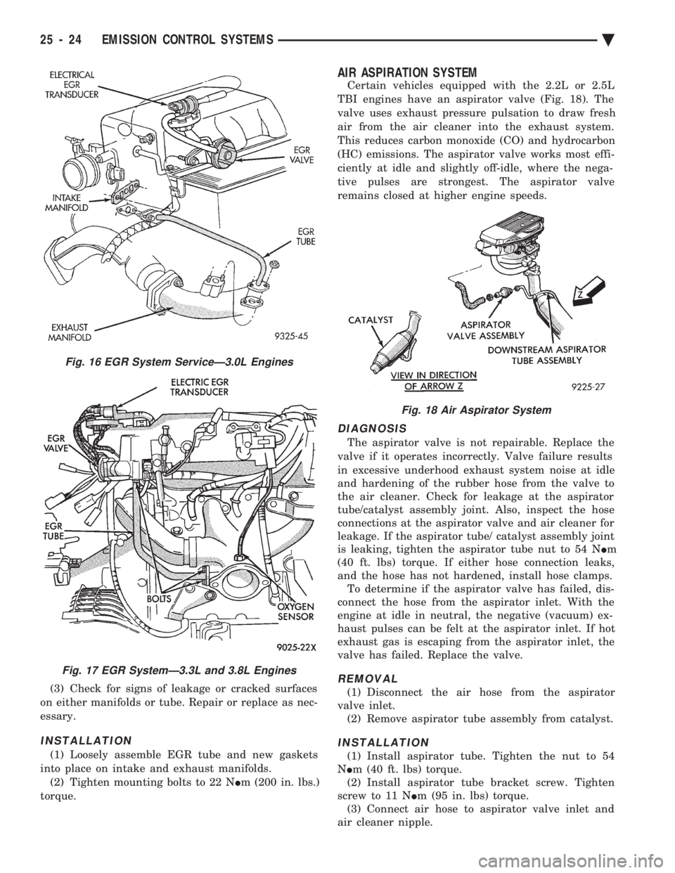
(3) Check for signs of leakage or cracked surfaces
on either manifolds or tube. Repair or replace as nec-
essary.
INSTALLATION
(1) Loosely assemble EGR tube and new gaskets
into place on intake and exhaust manifolds. (2) Tighten mounting bolts to 22 N Im (200 in. lbs.)
torque.
AIR ASPIRATION SYSTEM
Certain vehicles equipped with the 2.2L or 2.5L
TBI engines have an aspirator valve (Fig. 18). The
valve uses exhaust pressure pulsation to draw fresh
air from the air cleaner into the exhaust system.
This reduces carbon monoxide (CO) and hydrocarbon
(HC) emissions. The aspirator valve works most effi-
ciently at idle and slightly off-idle, where the nega-
tive pulses are strongest. The aspirator valve
remains closed at higher engine speeds.
DIAGNOSIS
The aspirator valve is not repairable. Replace the
valve if it operates incorrectly. Valve failure results
in excessive underhood exhaust system noise at idle
and hardening of the rubber hose from the valve to
the air cleaner. Check for leakage at the aspirator
tube/catalyst assembly joint. Also, inspect the hose
connections at the aspirator valve and air cleaner for
leakage. If the aspirator tube/ catalyst assembly joint
is leaking, tighten the aspirator tube nut to 54 N Im
(40 ft. lbs) torque. If either hose connection leaks,
and the hose has not hardened, install hose clamps. To determine if the aspirator valve has failed, dis-
connect the hose from the aspirator inlet. With the
engine at idle in neutral, the negative (vacuum) ex-
haust pulses can be felt at the aspirator inlet. If hot
exhaust gas is escaping from the aspirator inlet, the
valve has failed. Replace the valve.
REMOVAL
(1) Disconnect the air hose from the aspirator
valve inlet. (2) Remove aspirator tube assembly from catalyst.
INSTALLATION
(1) Install aspirator tube. Tighten the nut to 54
N Im (40 ft. lbs) torque.
(2) Install aspirator tube bracket screw. Tighten
screw to 11 N Im (95 in. lbs) torque.
(3) Connect air hose to aspirator valve inlet and
air cleaner nipple.
Fig. 16 EGR System ServiceÐ3.0L Engines
Fig. 17 EGR SystemÐ3.3L and 3.8L Engines
Fig. 18 Air Aspirator System
25 - 24 EMISSION CONTROL SYSTEMS Ä
Page 2421 of 2438
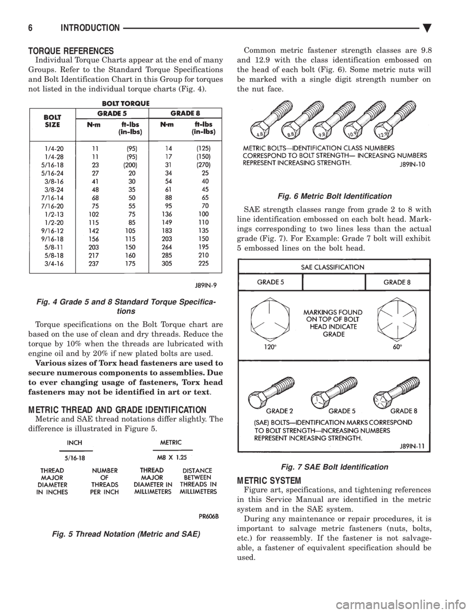
TORQUE REFERENCES
Individual Torque Charts appear at the end of many
Groups. Refer to the Standard Torque Specifications
and Bolt Identification Chart in this Group for torques
not listed in the individual torque charts (Fig. 4).
Torque specifications on the Bolt Torque chart are
based on the use of clean and dry threads. Reduce the
torque by 10% when the threads are lubricated with
engine oil and by 20% if new plated bolts are used. Various sizes of Torx head fasteners are used to
secure numerous components to assemblies. Due
to ever changing usage of fasteners, Torx head
fasteners may not be identified in art or text .
METRIC THREAD AND GRADE IDENTIFICATION
Metric and SAE thread notations differ slightly. The
difference is illustrated in Figure 5. Common metric fastener strength classes are 9.8
and 12.9 with the class identification embossed on
the head of each bolt (Fig. 6). Some metric nuts will
be marked with a single digit strength number on
the nut face.
SAE strength classes range from grade 2 to 8 with
line identification embossed on each bolt head. Mark-
ings corresponding to two lines less than the actual
grade (Fig. 7). For Example: Grade 7 bolt will exhibit
5 embossed lines on the bolt head.
METRIC SYSTEM
Figure art, specifications, and tightening references
in this Service Manual are identified in the metric
system and in the SAE system. During any maintenance or repair procedures, it is
important to salvage metric fasteners (nuts, bolts,
etc.) for reassembly. If the fastener is not salvage-
able, a fastener of equivalent specification should be
used.
Fig. 6 Metric Bolt Identification
Fig. 7 SAE Bolt Identification
Fig. 4 Grade 5 and 8 Standard Torque Specifica- tions
Fig. 5 Thread Notation (Metric and SAE)
6 INTRODUCTION Ä