Page 1045 of 1216
23-lBODY
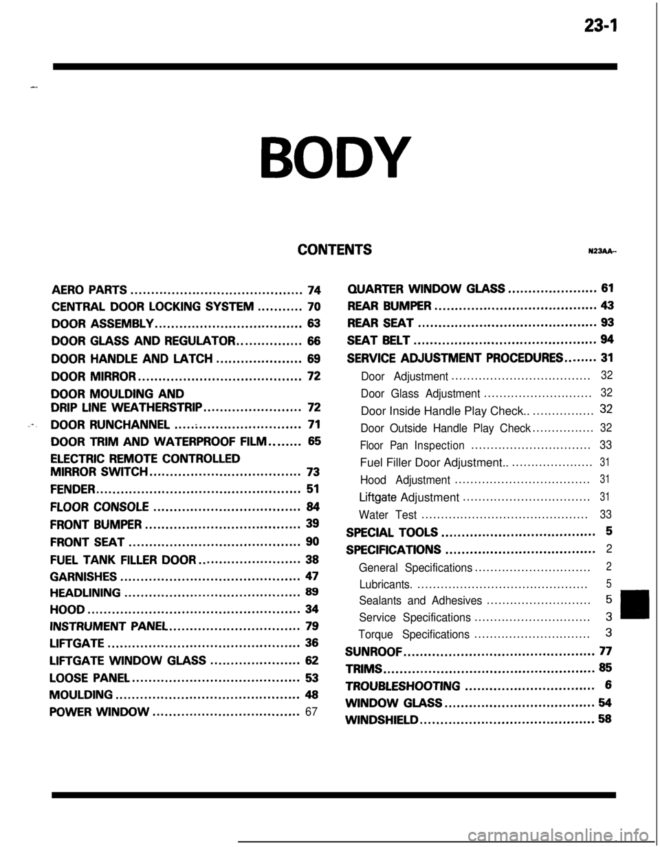
CONTENTSN23Ak-
AERO PARTS..........................................74
CENTRAL DOOR LOCKING SYSTEM...........70
DOOR ASSEMBLY....................................63
DOOR GLASS AND REGULATOR................66
DOORHANDLEANDLATCH.....................69
DOOR MIRROR........................................72
DOOR MOULDING AND
DRIP LINE WEATHERSTRIP........................72
....DOOR RUNCHANNEL...............................71
DOOR TRIM AND WATERPROOF FILM........65
ELECTRIC REMOTE CONTROLLED
MIRROR SWITCH.....................................73
FENDER..................................................51
FLOOR CONSOLE....................................84
FRONT BUMPER......................................39
FRONT SEAT..........................................90
FUEL TANKFILLERDOOR.........................38
GARNISHES............................................47
HEADLINING...........................................89
HOOD....................................................34
INSTRUMENT PANEL................................79
LIFTGATE...............................................36
LIFTGATE WINDOWGLASS......................62
LOOSE PANEL.........................................53
MOULDING.............................................48
POWER WINDOW....................................67
QUARTERWINDOWGLASS......................61
REAR BUMPER........................................43
REAR SEAT............................................93
SEAT BELT.............................................94
SERVICE ADJUSTMENT PROCEDURES........31
Door Adjustment....................................32
Door Glass Adjustment............................32Door Inside Handle Play Check..................
32
Door Outside Handle Play Check................32
Floor PanInspection...............................
33Fuel Filler Door Adjustment.......................
31
Hood Adjustment...................................31
Liftgate Adjustment.................................31
Water Test...........................................33
SPECIAL TOOLS......................................5
SPECIFICATIONS.....................................2
General Specifications..............................
2
Lubricants.............................................5
Sealants and Adhesives...........................5
Service Specifications..............................3
Torque Specifications..............................3
SUNROOF...............................................77TRIMS
....................................................85
TROUBLESHOOTING................................6WINDOW
GLASS.....................................54
WINDSHIELD...........................................58
Page 1047 of 1216
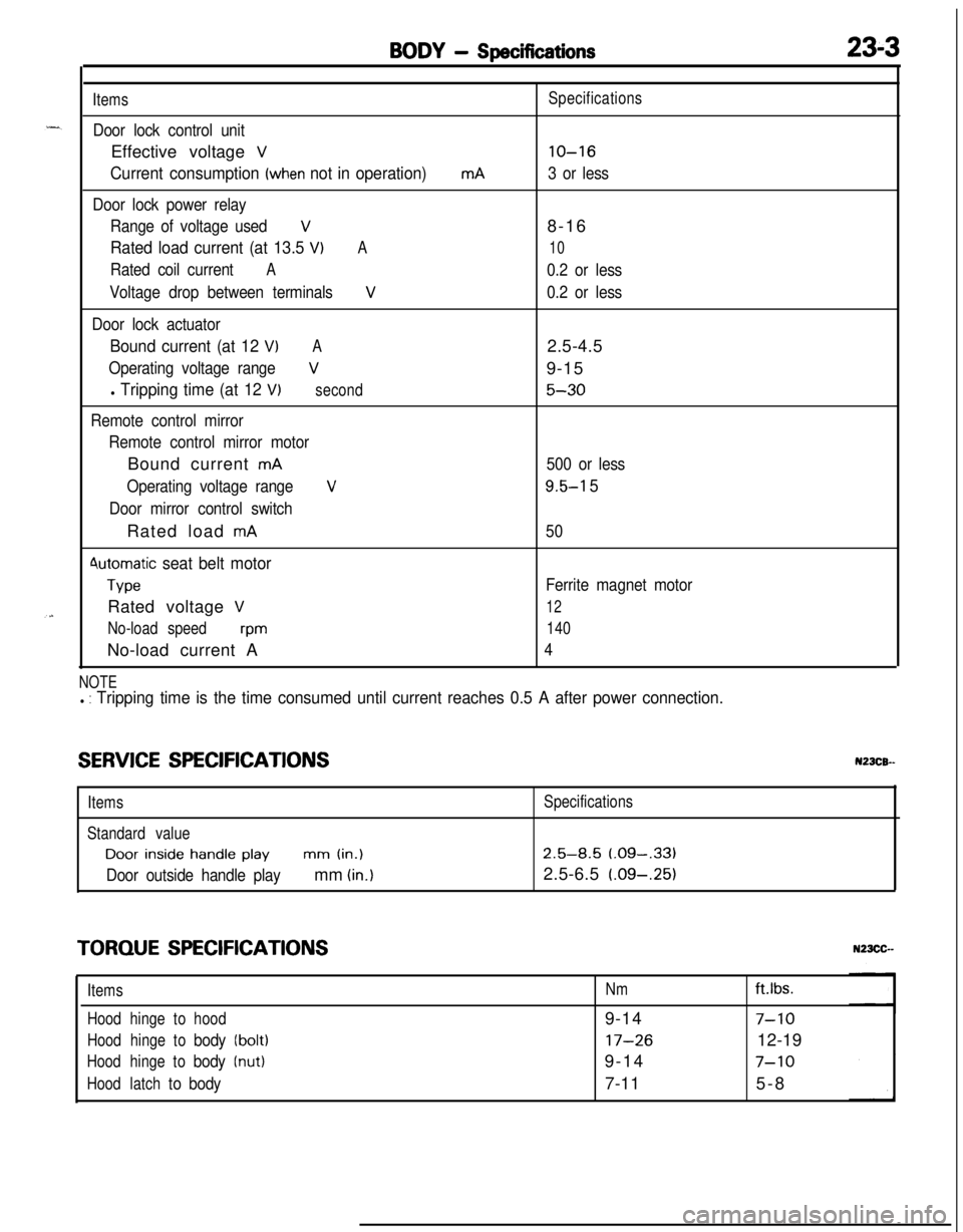
BODY - Specifications23-3
Items
Door lock control unitEffective voltage
V
Current consumption (when not in operation)
Door lock power relay
Range of voltage used
V
Rated load current (at 13.5 VIA
Rated coil currentA
Voltage drop between terminalsV
Door lock actuator
Bound current (at 12 VIA
Operating voltage rangeV
l Tripping time (at 12 V)second
Remote control mirror
Remote control mirror motorBound current
mA
Operating voltage range
V
Door mirror control switchRated load
mA
4utomatic seat belt motor
TypeRated voltage
V
No-load speedwmNo-load current A
mASpecifications
lo-16
3 or less8-16
10
0.2 or less
0.2 or less2.5-4.5
9-15
5-30
500 or less
9.5-l 5
50
Ferrite magnet motor
12
140
4
NOTEl : Tripping time is the time consumed until current reaches 0.5 A after power connection.
SERVICE SPECIFICATIONSN23CB--
ItemsSpecifications
Standard valueDoor
inside handle playmm (in.)2.5-8.5 (.09-,331
Door outside handle playmm (in.)2.5-6.5 (.09-.25)
TORQUE SPECIFICATIONS
ItemsNmft.lbs.
Hoodhingetohood9-14
7-10
Hoodhingetobody(bolt)17-2612-19
Hoodhingetobody(nut)9-147-10
Hoodlatchtobody7-115-8
Page 1075 of 1216
BODY - Service Adjustment Procedures23-31
16A0366
10A0370
SERVICE ADJUSTMENT PROCEDURES
HOOD ADJUSTMENTN23FAAK1. Loosen the hood mounting bolts, and then adjust the hood
by moving it so that the clearance is equal on all sides.
2. Turn the hood bumpers, adjust the height of the hood.
3. Loosen the food latch mounting bolts, and move the food
switch to adjust the attachment between the food switch
and food striker.
LIFTGATE ADJUSTMENTN23FCAE1. Loosen the
liftgate hinges mounting bolts, and then adjust
the liftgate by moving it so that the clearance is equal on all
sides.2. Loosen the
liftgate latch mounting bolts, and move the
liftgate latch to adjust the attachment between the liftgatelatch and
liftgate striker.
FUEL FILLER DOOR ADJUSTMENTN23FDAELoosen the fuel filler door mounting screw and adjust the fuel
filler door so that the clearance around the fuel filler door is evenwithout any height differences.
Page 1076 of 1216
23-32BODY - Service Adjustment Procedures
‘C16A0711
18AO38t
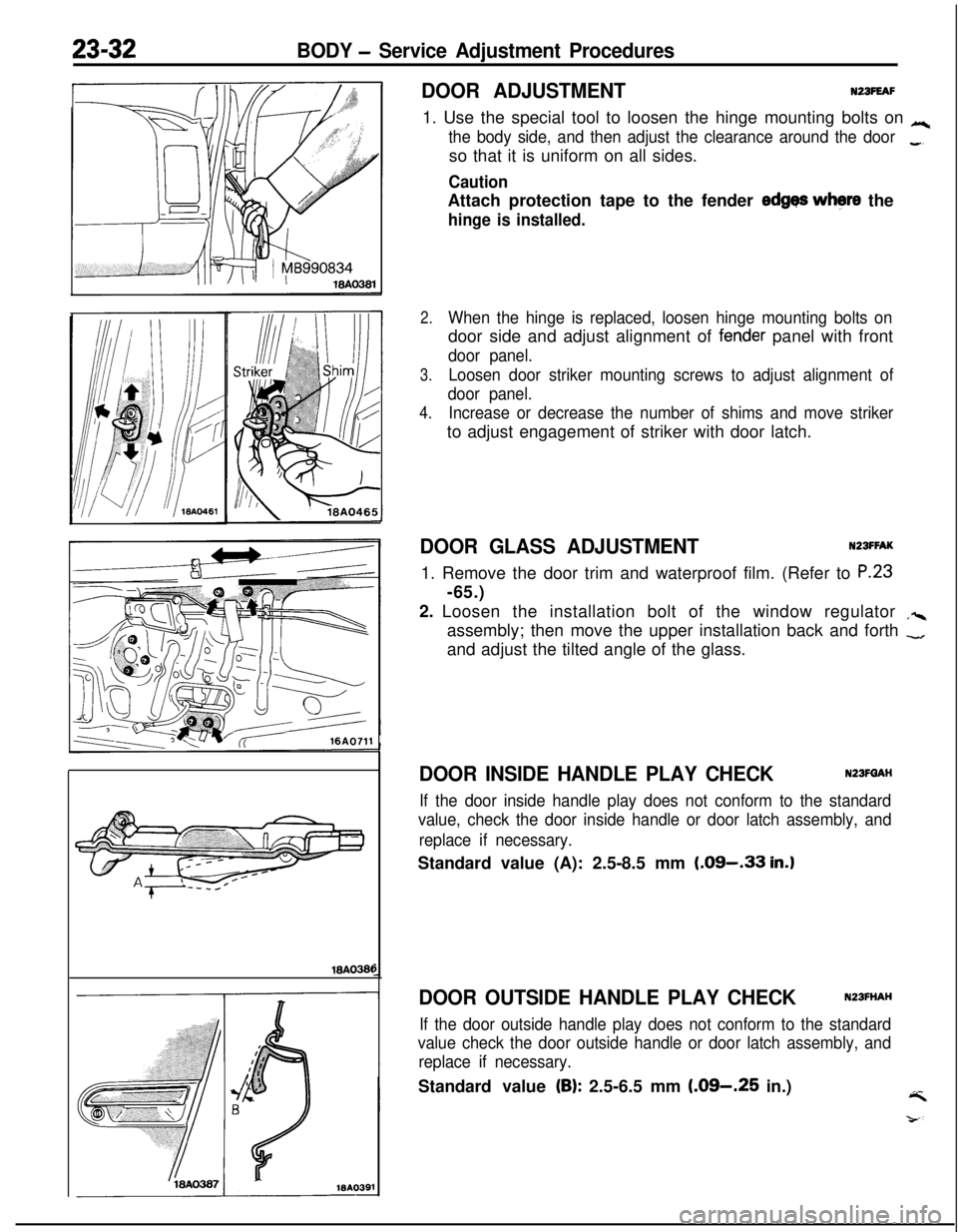
DOOR ADJUSTMENTNZBFEAF1. Use the special tool to loosen the hinge mounting bolts on
Lc
the body side, and then adjust the clearance around the door_so that it is uniform on all sides.
CautionAttach protection tape to the fender
edges where the
hinge is installed.
2.When the hinge is replaced, loosen hinge mounting bolts ondoor side and adjust alignment of
fen,der panel with front
door panel.
3.Loosen door striker mounting screws to adjust alignment of
door panel.
4.Increase or decrease the number of shims and move strikerto adjust engagement of striker with door latch.
DOOR GLASS ADJUSTMENTNZSFFAK1. Remove the door trim and waterproof film. (Refer to
P.23-65.)
2. Loosen the installation bolt of the window regulator
,%assembly; then move the upper installation back and forth
-and adjust the tilted angle of the glass.
DOOR INSIDE HANDLE PLAY CHECKN23FQAH
If the door inside handle play does not conform to the standard
value, check the door inside handle or door latch assembly, and
replace if necessary.Standard value (A): 2.5-8.5 mm
(.09-.33 in.)
DOOR OUTSIDE HANDLE PLAY CHECKN23FHAH
If the door outside handle play does not conform to the standard
value check the door outside handle or door latch assembly, and
replace if necessary.Standard value
(B): 2.5-6.5 mm (.09-.25 in.)4
Page 1077 of 1216
BODY - Service Adiistment Procedures23-33
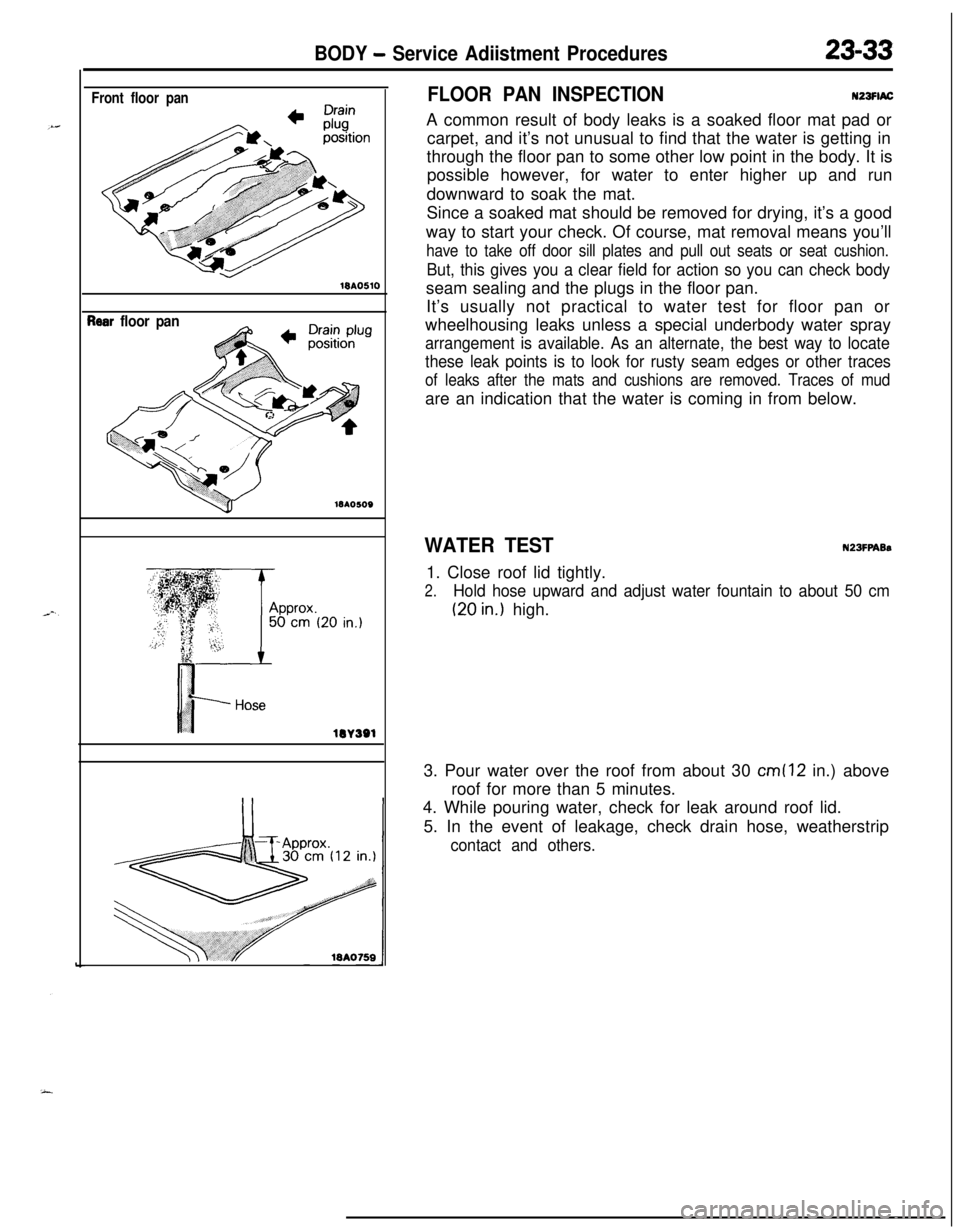
Front floor pan18AO510
?ear floor pan
lOA
lW391
FLOOR PAN INSPECTIONN23FlACA common result of body leaks is a soaked floor mat pad or
carpet, and it’s not unusual to find that the water is getting in
through the floor pan to some other low point in the body. It is
possible however, for water to enter higher up and run
downward to soak the mat.
Since a soaked mat should be removed for drying, it’s a good
way to start your check. Of course, mat removal means you’ll
have to take off door sill plates and pull out seats or seat cushion.
But, this gives you a clear field for action so you can check bodyseam sealing and the plugs in the floor pan.
It’s usually not practical to water test for floor pan or
wheelhousing leaks unless a special underbody water spray
arrangement is available. As an alternate, the best way to locate
these leak points is to look for rusty seam edges or other traces
of leaks after the mats and cushions are removed. Traces of mudare an indication that the water is coming in from below.
WATER TESTN23FPABs1. Close roof lid tightly.
2.Hold hose upward and adjust water fountain to about 50 cm
(20 in.) high.
3. Pour water over the roof from about 30
cm (12 in.) above
roof for more than 5 minutes.
4. While pouring water, check for leak around roof lid.
5. In the event of leakage, check drain hose, weatherstrip
contact and others.
Page 1078 of 1216
23-34BODY - Hood
HOOD
REMOVAL AND INSTALLATION
N23HAA8
1518AO751
18A0438
LRemoval5
1.Bumper
2.Hood weatherstrip
3.Heat protector4.Hood weatherstrip
5. Headlight hood protector
I)+ 6.Bumper7. Hood support rod
8.Bumper9. Hood switch
theft-alarm system
>10.Bumper11.Bumper bracketl *I 12. Hood lock release handlel 13. Hood latch
NOTE
(1) Reverse the removal procedures to reinstall.(2) l 4 : Refer to “Service Points of Installation”.Hood lock release cable removal steps
l 12. Hood lock release handle
w 13. Hood latch
14. Protector15. Hood lock release cable
Hood removal steps
;f3: “,;n,yction for washer tube and nozzle
Hood hinge removal steps
17: ig?ction for washer tube and nozzle
Windshield wiper arms (Refer to GROUP
8-Windshield Wiper.)
18. Front deck garnish
,*I 19. Hood hinge
1
INSPECTIONHOOD SWITCH(I
1 Disconnect the hood switch connector.
(2) Check the continuity between the terminal.
WA0754lBRO665
)
NOTE
m indicates that there is continuity between the terminals.
Page 1080 of 1216
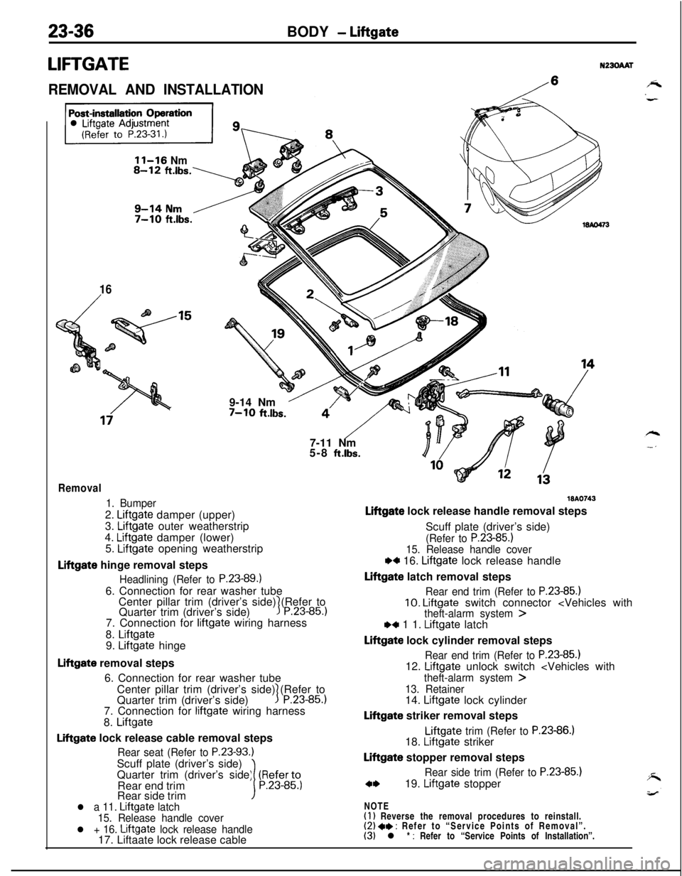
23-36BODY - Liftgate
LIFTGATEN230AAT
REMOVAL AND INSTALLATION/
11-16 Nm
16
/9-14 Nm
’7-10 ft.lbs.
“‘/- -$j7-11 Nm
5-8
ft.lbs.
Removal
1. Bumper2.
Liftgate damper (upper)
3.
Liftgate outer weatherstrip
4.
Liftgate damper (lower)
5. Liftgate opening weatherstrip
Liftgate hinge removal steps
Headlining (Refer to P.23-89.16. Connection for rear washer tube
Center pillar trim (driver’s side) (Refer to
Quarter trim (driver’s side)
3P.23-85.)7. Connection for
liftgate wiring harness
8.
Liftgate9. Liftgate hinge
Liftgate removal steps
6. Connection for rear washer tube
Center pillar trim (driver’s side) (Refer to
Quarter trim (driver’s side)
1P.23-85.)7. Connection for
liftgate wiring harness
8.
Liftgate
Liftgate lock release cable removal steps
Rear seat (Refer to P.23-93.)Scuff plate (driver’s side)
Quarter trim (driver’s side) (Referto
Rear end trim
1P.23-85.)Rear side trim
l a 11. Liftgate latch
15. Release handle cover
l + 16. Liftgate lock release handle17. Liftaate lock release cable
WA0743
Liftgate lock release handle removal steps
Scuff plate (driver’s side)
(Refer to P.23-85.)15. Release handle cover
w 16. Liftgate lock release handle
Liftgate latch removal steps
Rear end trim (Refer to P.23-85.)10. Liftgate switch connector ,4 1 1. Liftgate latch
Liftgate lock cylinder removal steps
Rear end trim (Refer to P.23-85.112. Liftgate unlock switch
theft-alarm system >
13. Retainer14. Liftgate lock cylinder
Liftgate striker removal stepsLiftgate
trim (Refer to P.23-86.)18. Liftgate striker
Liftgate stopper removal steps
Rear side trim (Refer to P.23-85.)
c*19. Liftgate stopper
NOTE
(1) Reverse the removal procedures to reinstall.(2) 4* : Refer to “Service Points of Removal”.(3) l * : Refer to “Service Points of Installation”.
Page 1081 of 1216
BODY - Liftnate23-37
SERVICE POINTS OF REMOVAL
19. REMOVAL OF LIFTGATE STOPPER
Caution
1. Never try to disassemble the liigate gas spring or
bum it.
2. Always bore a hole in the gas
spring to release the
interior gas before the spring is discarded.
INSPECTION
LIFTGATE SWITCH(I
1 Unlock the liftgate latch.
(2) Check the continuity between the terminals.
Terminal
Liftgate latch locked
Liftgate latch unlocked
1200
NOTE
o(> indicates that there is continuity between the terminals.
LIFTGATE LOCK CYLINDER SWITCH
Check to be sure that there is continuity between connector
terminals 1 and 2 when the switch part shown in the illustrationis not pressed, and that there is no longer continuity when it is
pressed.
SERVICE POINTS OF INSTALLATION
16.APPLlCATlON OF GREASE TO LIFTGATE LOCK
RELEASE HANDLE/ 11. LIFTGATE LATCHApply multipurpose grease to all moving parts.
Grease: MOPAR Multipurpose Grease Part No.
2932524 or equivalent