Page 1106 of 1216
23-62BODY - Liftgate Window Glass
LIFTGATE WINDOW GLASSN22LDAK
REMOVAL AND INSTALLATION
Pre-removal Operation*Removal of Liftgate Trim and Flange
Trim
(Refer to
P.23-86.)aRemoval of Air Spoiler
(Refer to P.23-74.)Post-installation Operation
*Installation of Air Spoiler
(Refer to
P.23-74.)*Installation of Liftgate Trim and
Flange Trim
(Refer to
P.23-86.)
I
Removal steps
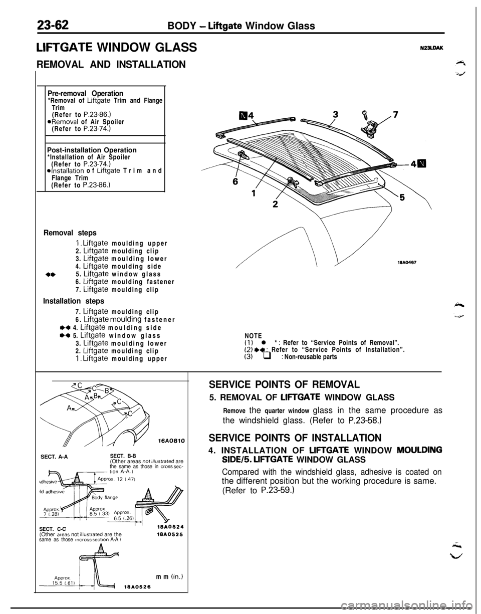
I. Liftgate moulding upper
2. Liftgate moulding clip
3. Liftgate moulding lower
4. Liftgate moulding side
o*5. Liftgate window glass
6. Liftgate moulding fastener
7.
Liftgate moulding clip
Installation steps7.
Liftgate moulding clip
6.
Liftgate moulding fastener
M 4. Liftgate moulding side
w 5. Liftgate window glass
3.
Liftgate moulding lower
2. Liftgate moulding clip1. Liftgate moulding upper
WA0487NOTE
(1) l * : Refer to “Service Points of Removal”.(2) .+ : Refer to “Service Points of Installation”.(3) q : Non-reusable parts
SECT. A-A
SECT. B-B(Other areas not illustrated arethe same as those in cmss sec-
SECT. C-C(Other areas not illustrated are thesame as those ,ncrms sectmn A-A )1ar40525mm
(in.)
ISA0526
SERVICE POINTS OF REMOVAL5. REMOVAL OF
LIFTGATE WINDOW GLASS
Remove the quarter window glass in the same procedure as
the windshield glass. (Refer to
P.23-58.)
SERVICE POINTS OF INSTALLATION4. INSTALLATION OF
LIFTGATE WINDOW MOULDINGSIDE/5.
LIFTGATE WINDOW GLASS
Compared with the windshield glass, adhesive is coated onthe different position but the working procedure is same.
(Refer to
P.23-59.)
Page 1107 of 1216
BODY - Door AssemblvDOOR ASSEMBLY
- REMOVAL AND INSTALLATION
N22MAW17-26
12-19
17-26
12-19
15A0511
Removal steps
1. Connection for door wiring harness
connector
*+ 2. Spring pin
3. Door assembly
l 4. Upper hinge
.c 5. Lower hinge6. Striker7. Striker shim
8. Door switch cap
9. Door switch
l * 10. Door check strap
0 Removal of Cowl Side Trim(Refer to P.23-85.)
l Installation of Cowl Side Trim(Refer to P.23-85.)
0 Door Adjustment
NOTE(I) Reverse the removal procedures to reinstall.(2) I)+ : Refer to “Service Points of Instal$tion”.
Page 1108 of 1216
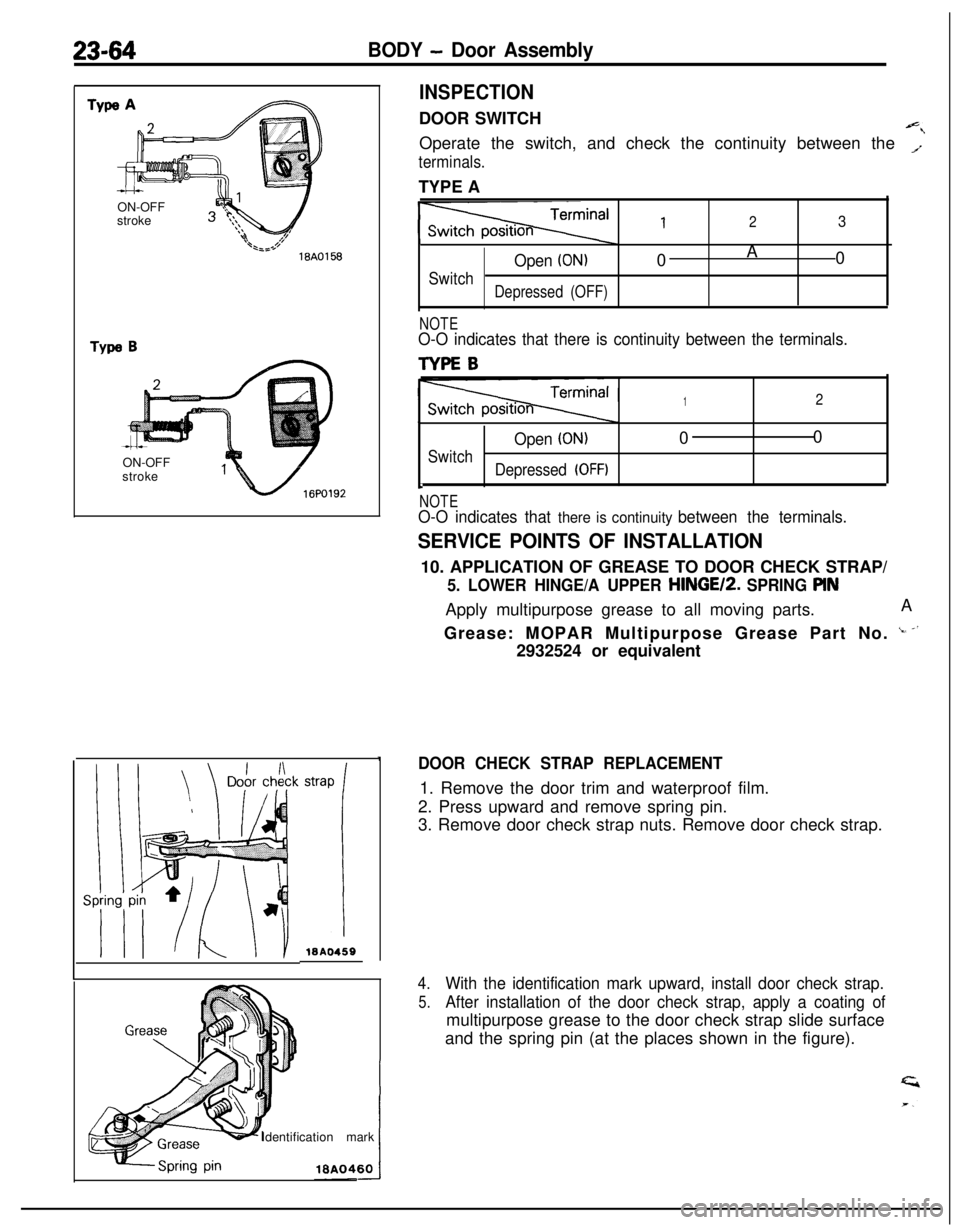
23-64BODY - Door AssemblyON-OFF
stroke
1*,,.$18A0158
Type BON-OFF
stroke
“1 /- 16PO192klBA0459
Identification mark
INSPECTIONDOOR SWITCH
Operate the switch, and check the continuity between the
T
terminals.TYPE A
123
Open (ON)0A
0
SwitchDepressed (OFF)
NOTEO-O indicates that there is continuity between the terminals.
TYPEB
12
Open (ON)00
Switch
Depressed (OFF)b
NOTEO-O indicates that there is continuity between the terminals.
SERVICE POINTS OF INSTALLATION10. APPLICATION OF GREASE TO DOOR CHECK STRAP/
5. LOWER HINGE/A UPPER HINGE12. SPRING PINApply multipurpose grease to all moving parts.A
Grease: MOPAR Multipurpose Grease Part No.
‘- -’2932524 or equivalent
DOOR CHECK STRAP REPLACEMENT1. Remove the door trim and waterproof film.
2. Press upward and remove spring pin.
3. Remove door check strap nuts. Remove door check strap.
4.With the identification mark upward, install door check strap.
5.After installation of the door check strap, apply a coating ofmultipurpose grease to the door check strap slide surface
and the spring pin (at the places shown in the figure).
Page 1109 of 1216
BODY - Door Trim and Waterproof Film2345
DOOR TRIM AND WATERPROOF FILM
REMOVAL AND INSTALLATIONI
Power window provided vehicle%l \PL
< Oriver’s seat side>
2i36~4
15AO514<
Passenaer’s
seat
side >
er window provkkd
Removal steps2. Door window regulator handle
3. Escutcheon
4. Door grip mounting screw
5. Pull handle box
l *6. Door trim
l +1. Clip
7. Power window switchWA05138. Electrical remote control mirror switch
9. Door grip
10. Pull handle bracket
11. Door grip lower bracketNOTE
(1) Reverse the removal procedures to reinstall.12. Door trim bracket B(2) a* : Refer to “Service Points of Removal”.13. Door trim bracket
C(3) +* : Refer to “Service Points of Installa~lon”,
*c 14. Waterproof film(4) +shows the installation position of trim Clip.
I
Page 1110 of 1216
23-66BODY - Door Trim and Waterproof Film/Door Glass and Regulator
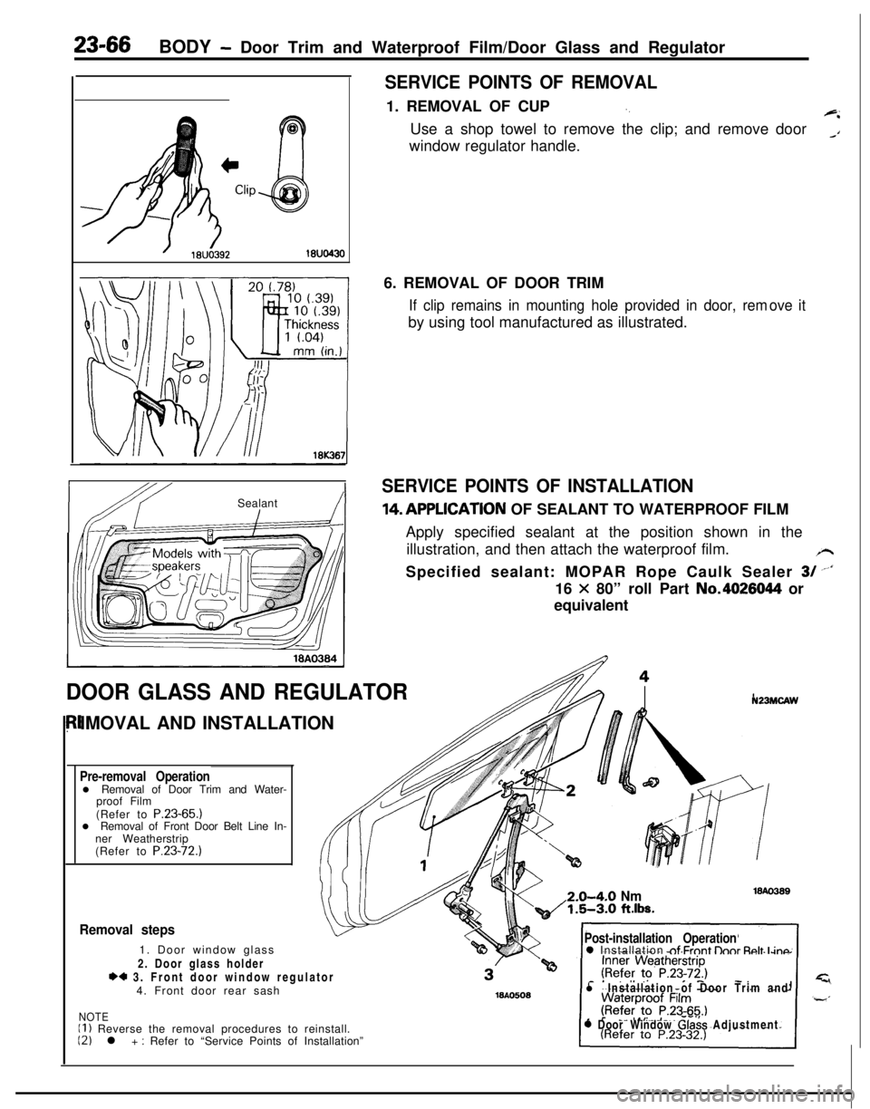
SERVICE POINTS OF REMOVAL1. REMOVAL OF CUP
‘.+iUse a shop towel to remove the clip; and remove door
_Awindow regulator handle.
IbY ISealant!I6. REMOVAL OF DOOR TRIM
If clip remains in mounting hole provided in door, remby using tool manufactured as illustrated.ove it
SERVICE POINTS OF INSTALLATION14,APPLlCATlON OF SEALANT TO WATERPROOF FILM
Apply specified sealant at the position shown in the
illustration, and then attach the waterproof film.
/rSpecified sealant: MOPAR Rope Caulk Sealer
3/ --‘I16
X 80” roll Part No.4026044 or
equivalent
DOOR GLASS AND REGULATORIMOVAL AND INSTALLATION
Pre-removal Operationl Removal of Door Trim and Water-
proof Film
(Refer to P.23-65.)
l Removal of Front Door Belt Line In-
ner Weatherstrip
(Refer to P.23-72.)
N23MCAW2.0-4-O
Nm1.5-3.0 ft.lbs.
Removal steps1. Door window glass
2. Door glass holder
*4 3. Front door window regulator
4. Front door rear sash
NOTEII ) Reverse the removal procedures to reinstall.12) l + : Refer to “Service Points of Installation”
Post-installation Operation0 Installation nf Frnnt lhnr Rnlt I inn
l Installation of Door Trim and
0 Door Window Glass Adjustment
Page 1111 of 1216
BODY - Door Glass and Reaulator/Power Window23-67
POWER WINDOW
REMOVAL AND INSTALLATIONSERVICE POINTS OF INSTALLATION3. APPLICATION OF GREASE TO FRONT DOOR WINDOW
REGULATORApply multipurpose grease to all moving parts.
Grease: MOPAR Multipurpose Grease Part No.
2932524 or equivalent
N23MHAEa
71l Door Window Glass Adjustment
< Passenger’s seat side >NOTE
(1) Reverse the removal procedures to reinstall.(2) l + : Refer to “Service Points of Installation”.
1810469Power window relay removal
1. Power window relay
Power window switch removal steps
Door trim (Refer to P.23-65.)2. Power window main switch
3. Power window sub switch
Power window motor removal steps
Door trim and waterproof film
(Refer to
P.23-65.)4. Door window glass
l + 5. Front door window regulator
16l.03443 416AO606
INSPECTIONPOWER WINDOW RELAY
Apply battery voltage to terminal 2, and check for continuity
when terminal 4 is grounded.
NOTEO-O indicates that there is continuity between the terminals.
Page 1113 of 1216
BODY - Power Window/Door Handle and Latch23-69
I-
DOOR HANDLE AND LATCHPOWER WINDOW SUB SWITCH
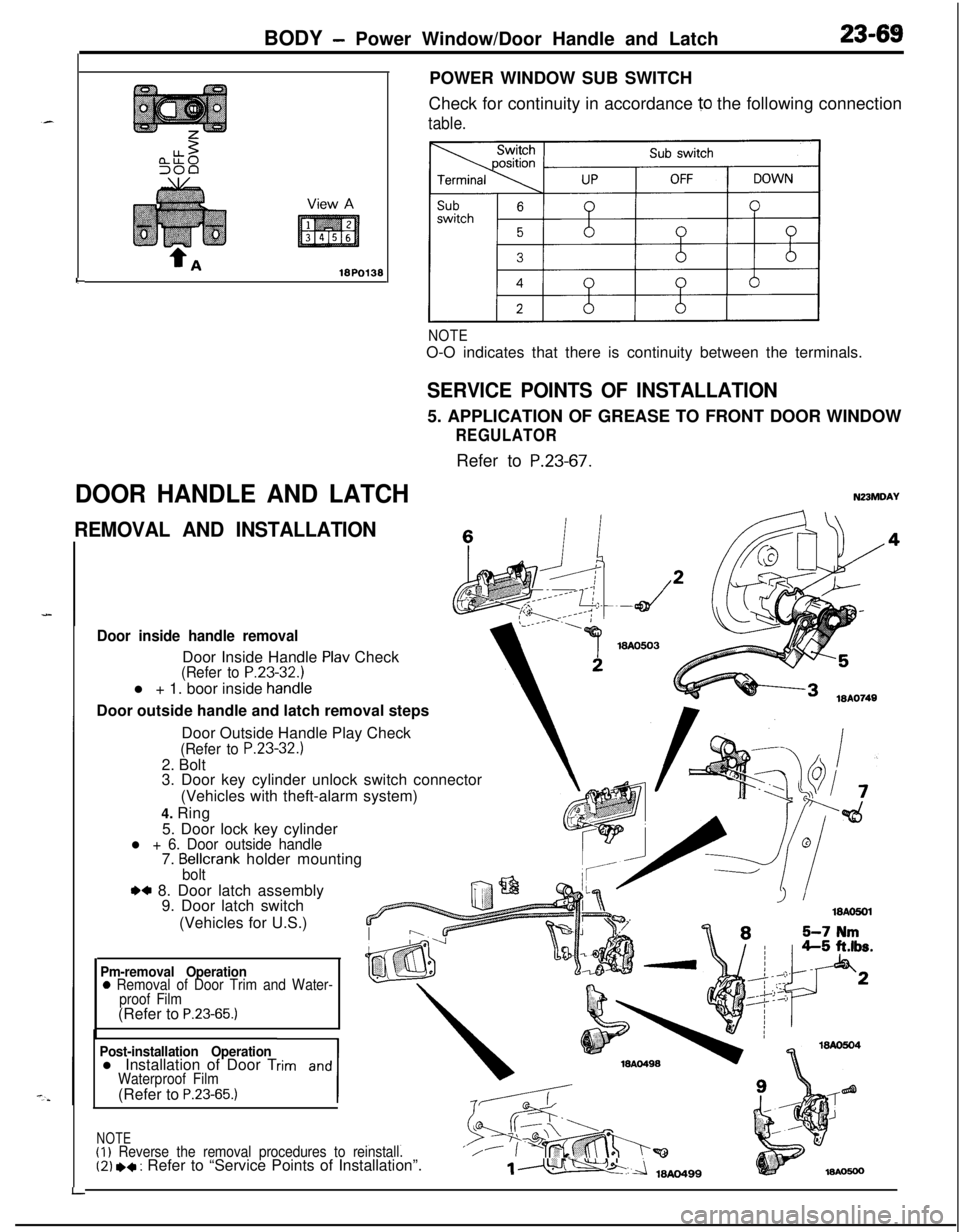
Check for continuity in accordance
10 the following connection
table.
NOTEO-O indicates that there is continuity between the terminals.
SERVICE POINTS OF INSTALLATION5. APPLICATION OF GREASE TO FRONT DOOR WINDOW
REGULATORRefer to
P.23-67.
N23MDAY
REMOVAL AND INSTALLATIONc
Door inside handle removalDoor Inside Handle
Plav Check(Refer to P.23-32.1l + 1. boor inside
handieDoor outside handle and latch removal steps
LDoor Outside Handle Play Check
(Refer to P.23-32.)2. Bolt
3. Door key cylinder unlock switch connector
(Vehicles with theft-alarm system)
4. Ring
5. Door lock key cylinder
l + 6. Door outside handle7. Bellcrank holder mountingbolt
.a 8. Door latch assembly
9. Door latch switch
(Vehicles for U.S.)
Pm-removal Operation0 Removal of Door Trim and Water-
proof Film(Refer to
P.23-65.)
Post-installation Operationl Installation of Door Trim and
1
Waterproof Film(Refer to P.23-65.)
NOTE(I)
Reverse the removal procedures to reinstall.‘/(2) *+ : Refer to “Service Points of Installation”.1m
Page 1114 of 1216
23-70BODY- Door Handle and Latch/Central Door Lockina Svstem
I18AO750 1lBY3611 I.- .--,
!-
II
T!3123
18PO39i
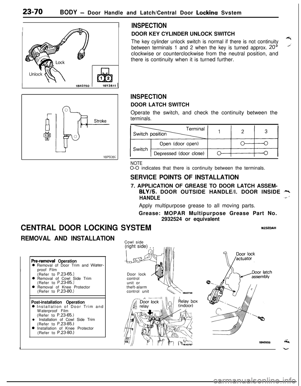
INSPECTIONDOOR KEY CYLINDER UNLOCK SWITCH
The key cylinder unlock switch is normal if there is not continuity7
between terminals 1 and 2 when the key is turned approx. 20”’clockwise or counterclockwise from the neutral position, and
there is continuity when it is turned further.
INSPECTIONDOOR LATCH SWITCH
Operate the switch, and check the continuity between the
terminals.
NOTEO-O indicates that there is continuity between the terminals.
SERVICE POINTS OF INSTALLATION7. APPLICATION OF GREASE TO DOOR LATCH ASSEM-
BLY/5. DOOR OUTSIDE HANDLE/l. DOOR INSIDE rr,
HANDLE.< ‘Apply multipurpose grease to all moving parts.
Grease: MOPAR Multipurpose Grease Part No.
2932524 or equivalent
CENTRAL DOOR LOCKING SYSTEMN23ZDAI-I
REMOVAL AND INSTALLATION
Pre-removal Operation0 Removal of Door Trim and Water-
Iproof Film
(Refer to P.23-65.)
0 Removal of Cowl Side Trim
(Refer to P.23-85.)
0 Removal of Knee Protector
(Refer to P.23-80.)
Post-installation Operation0 Installation of Door Trim and
Waterproof Film
(Refer to P.23-65.)
l Installation of Cowl Side Trim
(Refer to P.23-85.)
0 Installation of Knee Protector
(Refer to P.23-80.)
ICowl side
(right side) , ,
Door lock
control
unit or
theft-alarm
control unit