Page 1116 of 1216

23-72BODY -Door Moulding and Drip Line Weatherstrip/Door Mirror
DOOR MOULDING AND DRIP LINE WEATHERSTRIPNZBMFAK
IEMOVAL AND INSTALLATION
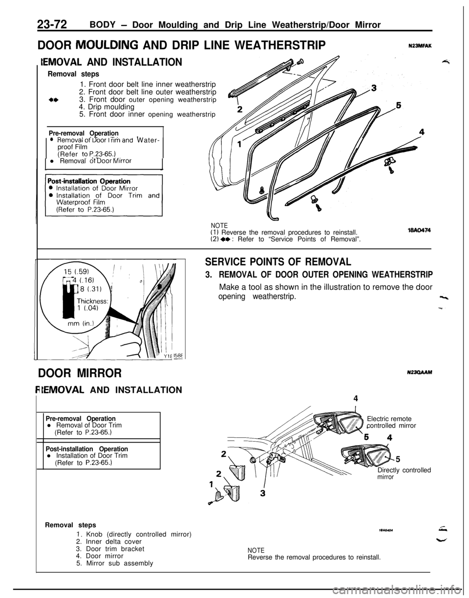
Removal steps1. Front door belt line inner weatherstrip
2. Front door belt line outer weatherstrip
3. Front door outer opening weatherstrip
&4. Drip moulding
5. Front door inner opening weatherstrip
Pre-removal Operation- ^II_ -..lHemOVal ot Uoor I rim and Water-
proof Film
(Refer to
P.23-65.) _,. -l Removal ot Door Mirror
NOTE(I 1 Reverse the removal procedures to reinstall.(2) +, : Refer to “Service Points of Removal”.
158E-
SERVICE POINTS OF REMOVAL
3.REMOVAL OF DOOR OUTER OPENING WEATHERSTRIPMake a tool as shown in the illustration to remove the door
opening weatherstrip.
N23OAAMDOOR MIRROR
IEMOVAL AND INSTALLATION
4
Pre-removal Operationl Removal of Door Trim
(Refer to
P.23-65.)
Post-installation Operationl Installation of Door Trim
(Refer to
P.23-65.)5
mirrorh-.Directly controlled Electric remote
controlled mirror
Removal steps
I. Knob (directly controlled mirror)
2. Inner delta cover
3. Door trim bracket
4. Door mirror
5. Mirror sub assemblymr(ol*.
NOTEReverse the removal procedures to reinstall.
Page 1118 of 1216
23-74BODY - Aero Parts
AERO PARTSN23XAAH
REMOVAL AND INSTALLATION
WA076318A0764
lQA0479Side air dam removal
l * l *1. Side air dam (door)
2. Air,dam clip+* l +3. Side air dam (side sill)
Rear air spoiler assembly (center) removal stepsRear wiper
(Refer to GROUP
8-Rear Wiper.)Liftgate trim (Refer to P.23-86.)
High mounted stop light
(Refer to GROUP
8-Lighting System.)
4. Rear wiper grommet
+w l c5. Rear air spoiler assembly (center)12. Spoiler tape
Rear air spoiler assembly (side) removal steps6. Mast antenna
7. Mounting nut
8. Mounting insulator
l * l a9. Rear air spoiler assembly (side)
10. Air spoiler bracket assembly
Door air spoiler removal
,+ 1 1. Door air spoiler
NOTE(1) Reverse the removal procedures to reinstall.(2) l + : Refer to “Service Points of Removal”.(3) l + : Refer to “Service Points of Installation”.
Page 1119 of 1216

BODY - Aero Parts23-75
\18A0245
16A0765
18A041618A041C
SERVICE POINTS OF REMOVAL
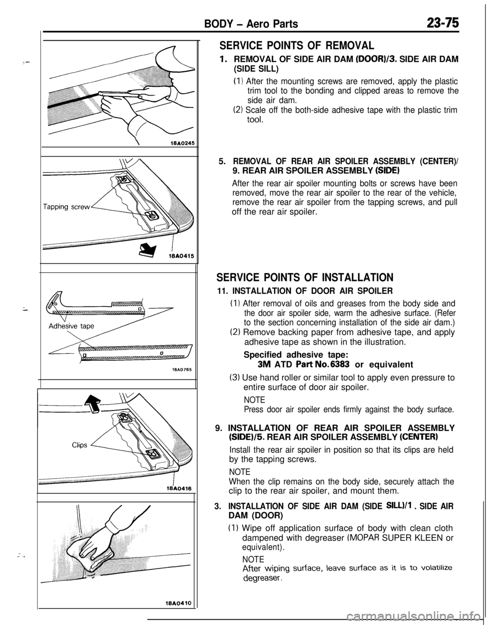
1.REMOVAL OF SIDE AIR DAM (DOOR)/3. SIDE AIR DAM
(SIDE SILL)(I
1 After the mounting screws are removed, apply the plastic
trim tool to the bonding and clipped areas to remove the
side air dam.
(21 Scale off the both-side adhesive tape with the plastic trim
tool.5.
REMOVAL OF REAR AIR SPOILER ASSEMBLY (CENTER)/9. REAR AIR SPOILER ASSEMBLY
(SIDE)
After the rear air spoiler mounting bolts or screws have been
removed, move the rear air spoiler to the rear of the vehicle,
remove the rear air spoiler from the tapping screws, and pulloff the rear air spoiler.
SERVICE POINTS OF INSTALLATION
11. INSTALLATION OF DOOR AIR SPOILER(I
1 After removal of oils and greases from the body side and
the door air spoiler side, warm the adhesive surface. (Refer
to the section concerning installation of the side air dam.)
(2) Remove backing paper from adhesive tape, and apply
adhesive tape as shown in the illustration.
Specified adhesive tape:
3M ATD Part No.6383 or equivalent
(3) Use hand roller or similar tool to apply even pressure to
entire surface of door air spoiler.
NOTE
Press door air spoiler ends firmly against the body surface.9. INSTALLATION OF REAR AIR SPOILER ASSEMBLY
(SIDE)/5. REAR AIR SPOILER ASSEMBLY (CENTER)
Install the rear air spoiler in position so that its clips are heldby the tapping screws.
NOTE
When the clip remains on the body side, securely attach theclip to the rear air spoiler, and mount them.
3.INSTALLATION OF SIDE AIR DAM (SIDE SILL)/1 . SIDE AIRDAM (DOOR)
(I 1 Wipe off application surface of body with clean cloth
dampened with degreaser
IMOPAR SUPER KLEEN or
equivalent).
NOTE
After wiping surface, leave surface as it is to volatilize
degreaser .
Page 1121 of 1216
BODY - Sunroof2397
SUNROOFN22TTBAD
-- REMOVAL AND INSTALLATION
demoval steps
1. Sunshade
2. Roof lid glass or deflector
3. Weatherstrip
+w ++ 4. Headlining
5. Base plate assembly
6. Hinge female assembly
+* 7. Splash shield
Quarter trim (Refer to P.23-85.)Center pillar trim (Refer to P.23-85.)
l
++ 8. Drain hose
NOTE(I 1 Reverse the removal procedures to reinstall.(2) ** : Refer to “Service Points of Removal”.(3) l * : Refer to “Service Points of Installation”.(4) m : Non-reusable parts.
SERVICE POINTS OF REMOVAL4. REMOVAL OF HEADLINING
Refer to P.23-89.
8. REMOVAL OF DRAIN HOSE
Tie a cord
at the end of the drain hose and pull out the drain
hose toward the vehicle interior.
Page 1122 of 1216
23-78BODY - Sunroof
25-35
mm
SERVICE POINTS OF INSTALLATION8. INSTALLATION OF DRAIN HOSE
AZ
(I) Tie the,cord (passed through at the time of removal) to. .ithe end of the drain hose.
(2) Pull the cord and pass t’he drain hose through.
(3) Install the grommet at the front side, and install so that
the amount of projection of the drain hose is as shown
in the figure.
7. INSTALLATION OF SPLASH SHIELD
Refer to
P.23-51.4. INSTALLATION OF HEADLINING
Refer to
P.23-89.
Page 1124 of 1216
23-80BODY - Instrument Panel
REMOVAL AND INSTALLATION
-?7
Removal steps
1. Plug2. Knee protecter assembly
3. Hood lock release handle
4. Column cover lower
5. Column cover upper
6. Cover
(A)7. Cluster panel assembly (A)8. Radio panel9. Radio or radio and tape player
10. Center air outlet assembly
11. Dial knob (A)12. Cluster panel assembly (B)13. Stopper
14. Glove box assembly
Nm6-9 ft.lk.15. Combination meter
16. Speedometer cable adapter
17. Speaker garnishes18. Bracket
19. Heater control assembly installation
screws
20. Lap cooler duct
21. Shower duct (L.H.122. Steering shaft mounting bolt(s)23. Instrument panel mounting screws
24. Instrument panel mounting bolts
25. Instrument panel assembly
NOTE(1) Reverse the removal procedures to reinstall.(2) l * : Refer to “Service Points of Removal”
Page 1125 of 1216
BODY - Instrument Panel23-81
SECT. A-A
Flat-tip
( - ) screwdriver19A0274
1910267
SERVICE POINTS OF REMOVAL
10. REMOVAL OF CENTER AIR OUTLET ASSEMBLY
Removing the paw1 of the center air outlet assembly with aflat-tip
( - 1 screwdriver,remove the center air outlet
assembly with the plastic trim tool.
16. REMOVAL OF SPEEDOMETER CABLE ADAPTER
(1) Disconnect the speedometer cable at the transaxle endof the cable.
(2) Pull the speedometer cable slightly toward the vehicle
interior, release the lock by turning the adapter to the leftor right, and then remove the adapter.
Page 1127 of 1216
BODY - Instrument Panel23-83
191026024. Air duct
(A)25. Air duct
(B)26.Distribution duct
27.Side defroster hoses
28. Defroster nozzle assembly
29. Side defroster grilles
30. Side air outlet assembly
31. Bracket
32. Combination meter wiring harness
connector connections33. Instrument panel wiring harness
34. Instrument panel pad
35.Vin plate
36.Instrument
panel
NOTE(I) Reverse the disassembly procedures to reassemble(2) 4, : Refer to “Service Points of Disassembly”.
SERVICE POINTS OF DISASSEMBLY32. DISCONNECTION OF COMBINATION METER WIRING
HARNESS CONNECTORS
Insert a flat-tip I- 1 screwdriver and open the tab of the
connector, and then remove the harness connectors.