Page 615 of 1216

REAR SUSPENSION - Rear Suspension Assembly17-5
REAR SUSPENSION ASSEMBLYu
-%. REMOVAL AND INSTALLATIONN17GAA
---i
--..17-26 Nm12-19
ft.lbs.9-14 Nm
7- 10 ft.lbs.
Pre-removal Operationl Removal of the Hole Cover(Refer to GROUP 23-Trims.)
Post-installation Operation@Installation of the Hole Cover
(Refer to GROUP
23-Trims.)l Checking and Adiustment of BrakeDisc De‘ilection ’(Refer to GROUP 5-Service Adjust-ment Procedures.)
l Checking and Adjustment of RearDisc Brake Dragging Torque
(Refer to GROUP &Service Adjust-ment Procedures.)
l Parking Brake Lever Stroke Adjust-ment
(Refer to GROUP 5-Service Adjust-ment Procedures.)
Removal steps
W l1. Rear speed sensor
2. Parking brake cable3. Brake hose and tube bracket
4.
Calioer assemblv
200-280 Nm144-168 ftlbs.
llAO293
40-50 Nm
29-36 ltlbs.80-100
Nm*58-72 ft.lbs.*5. Brake disc
’6.Hubcapl +7. Wheel bearing nut8.Tongued washer9. Rear hub bearing unit
10.Dust shield
4*11. Lateral rod mounting bolt (body side)12.Cap
t:
13. Shock absorber upper mounting nut
14. Trailing arm mounting bolt
4*15. Rear suspension assembly
NOTE(I) Reverse the removal procedures to reinstall.
(2) +e : Refer to “Service Points of Removal”.(31 ~~ : Refer to “Service Points of Installation”.
(4) q : Non-reusable parts
(5)
*: Indicates parts which should be temporarily tight-ened, and then fully tightened with the vehicle Inthe unladen condition.12AO336
Page 631 of 1216
REAR SUSPENSION - Rear Suspension Assemblv
REAR SUSPENSION ASSEMBLY
5.REMOVAL AND INSTALLATIONN17GA-BPost-installation Operation
l Check of Wheel Alignment(Refer to P.17-20.)@Check of ParkingBrakeLever Stroke
(Refer to GROUP 5-Service Adjust
ment Procedures.)
l installation of Hole Cover(Refer to GROUP 23-Trims.)9-14 Nm
7-10 ft.lbs.
/
12AO640
\lo-15 Nm7-l 1 ft.lbs.
30-40 Nm
22-29 ft.lbs.
Removal steps
1. Shock absorber installation nut
2. Brake tube bracket installation bolt
l +3. Parking brake cable end
**4. Caliper assembly
5. Center exhaust pipe!rEeverse the removal procedures to reinstall.
6. Gasket(2) 4e: Refer to “Service Points of Removal”.
7. Gasket(3) l + : Refer to “Service Points of Installation”.’+I)
l +8. Propeller shaft installation bolt and nut(4) m : Non-reusable parts
Page 642 of 1216
17-32REAR SUSPENSION - Shock Absorber Assembly
SHOCK ABSORBER ASSEMBLY
REMOVAL AND INSTALLATION+4zNI’INA-B
40-50 Nm
29-36 ft.lbs.
/
12AO303Post-installation Operation
l installation of Trunk Room Trim(Refer to GROUP 23-Trims.)Removal steps
NOTE
Reverse the removal procedures to reinstall.
1. Shock absorber upper installation nut
2. Brake tube bracket installation bolt
3. Shock absorber lower installation bolt
4. Shock absorber assembly
h
Page 1045 of 1216

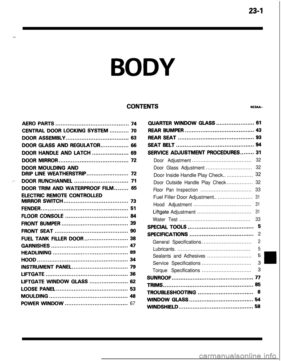
23-lBODY
CONTENTSN23Ak-
AERO PARTS..........................................74
CENTRAL DOOR LOCKING SYSTEM...........70
DOOR ASSEMBLY....................................63
DOOR GLASS AND REGULATOR................66
DOORHANDLEANDLATCH.....................69
DOOR MIRROR........................................72
DOOR MOULDING AND
DRIP LINE WEATHERSTRIP........................72
....DOOR RUNCHANNEL...............................71
DOOR TRIM AND WATERPROOF FILM........65
ELECTRIC REMOTE CONTROLLED
MIRROR SWITCH.....................................73
FENDER..................................................51
FLOOR CONSOLE....................................84
FRONT BUMPER......................................39
FRONT SEAT..........................................90
FUEL TANKFILLERDOOR.........................38
GARNISHES............................................47
HEADLINING...........................................89
HOOD....................................................34
INSTRUMENT PANEL................................79
LIFTGATE...............................................36
LIFTGATE WINDOWGLASS......................62
LOOSE PANEL.........................................53
MOULDING.............................................48
POWER WINDOW....................................67
QUARTERWINDOWGLASS......................61
REAR BUMPER........................................43
REAR SEAT............................................93
SEAT BELT.............................................94
SERVICE ADJUSTMENT PROCEDURES........31
Door Adjustment....................................32
Door Glass Adjustment............................32Door Inside Handle Play Check..................
32
Door Outside Handle Play Check................32
Floor PanInspection...............................
33Fuel Filler Door Adjustment.......................
31
Hood Adjustment...................................31
Liftgate Adjustment.................................31
Water Test...........................................33
SPECIAL TOOLS......................................5
SPECIFICATIONS.....................................2
General Specifications..............................
2
Lubricants.............................................5
Sealants and Adhesives...........................5
Service Specifications..............................3
Torque Specifications..............................3
SUNROOF...............................................77TRIMS
....................................................85
TROUBLESHOOTING................................6WINDOW
GLASS.....................................54
WINDSHIELD...........................................58
Page 1129 of 1216
BODY - Trims23-85
TRIMS
‘A REMOVAL AND INSTALLATION
6,Cowl side trim removal steps
1. Scuff plate
2. Cowl side trim
Quarter trim removal steps
Rear seat (Refer to P.23-93.1. Scuff plate
a*5. Quarter trim
6. Quarter trim lower bracket
Center shelf removal steps
3. Center shelf
4. Shelf holder
Rear end trim removal steps
7. Lid
(B)8. Lid
(D)4*9. Rear end trim
10. Bracket11. FWD bracket
12. AWD trim bracket
35-65 Nm25-40 ftlbs.
19AO413Rear side trim removal steps
Rear seat (Refer to P.2393.11. Scuff plate
3. Center shelf4. Shelf holder
4*5. Quarter trim
7. Lid tB)-. _ -8. Lid (D)l *9. Rear end trim
13. Rear seat belt anchor plate
14. Retractor cover
15. Rear seat belt protector
a*16. Rear side trim
17. Shelf catcher
18. Rear speaker bracket assembly1 S.‘Quarter trim upper bracket
NOTEFor the bolts indicated by the h. screws are
used for the left side.
Page 1130 of 1216

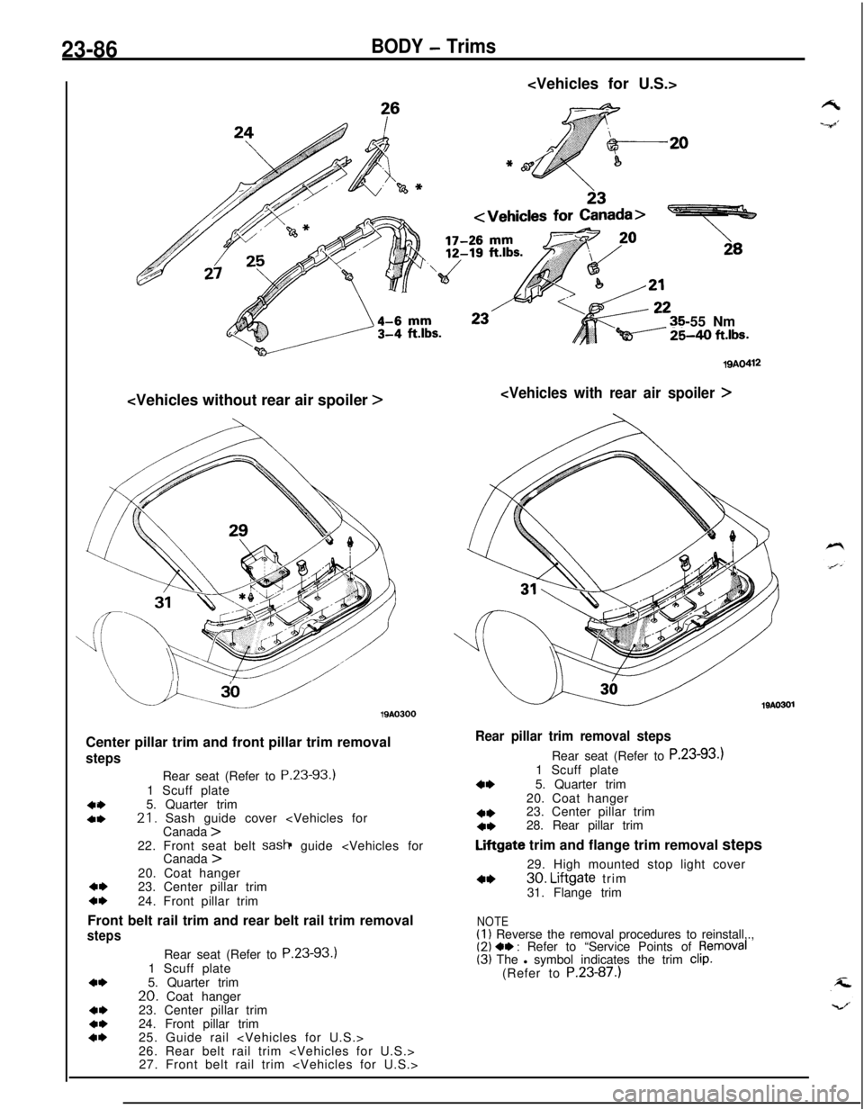
23-86BODY - Trims
-55 Nm
Qi----- %40 ft.lbs.
>
u.u19AO300
Center pillar trim and front pillar trim removal
steps
404,Rear seat (Refer to P.23-93.)
1 Scuff plate
5. Quarter trim21. Sash guide cover
Canada >22. Front seat belt sash guide
Canada >20. Coat hanger
4,23. Center pillar trimc*24. Front pillar trim
Front belt rail trim and rear belt rail trim removal
steps
4*
4,4*4*Rear seat (Refer to P.23-93.)
1 Scuff plate
5. Quarter trim
20. Coat hanger
23. Center pillar trim
24. Front pillar trim
25. Guide rail
26. Rear belt rail trim
27. Front belt rail trim
19AO412
19AO301
Rear pillar trim removal stepsRear seat (Refer to P.23-93.)
1 Scuff plate
4*5. Quarter trim
20. Coat hanger
4*23. Center pillar trim4*28. Rear pillar trim
Liftgate trim and flange trim removal steps
29. High mounted stop light cover
4*30. Liftgate trim
31. Flange trim
NOTE(1) Reverse the removal procedures to reinstall,.,(2) 4, : Refer to “Service Points of pemoval(3) The l symbol indicates the trim clip.(Refer to P.23-87.)
Page 1131 of 1216

BODY - Trims23-871@Poo70
10P0081
Trim
Gro19P0000
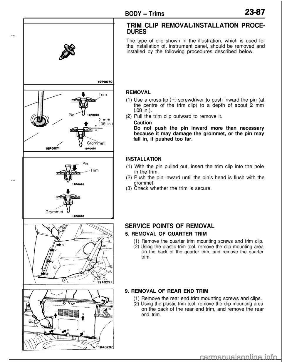
TRIM CLIP REMOVAL/INSTALLATION PROCE-
DURESThe type of clip shown in the illustration, which is used for
the installation of. instrument panel, should be removed and
installed by the following procedures described below.
REMOVAL
(1) Use a cross-tip (+) screwdriver to push inward the pin (at
the centre of the trim clip) to a depth of about 2 mm
(.08 in.).
(2) Pull the trim clip outward to remove it.
CautionDo not push the pin inward more than necessary
because it may damage the grommet, or the pin may
fall in, if pushed too far.
INSTALLATION(1) With the pin pulled out, insert the trim clip into the hole
in the trim.
(2) Push the pin inward until the pin’s head is flush with the
grommet.(3) Check whether the trim is secure.
SERVICE POINTS OF REMOVAL5. REMOVAL OF QUARTER TRIM
(1) Remove the quarter trim mounting screws and trim clip.
(2) Using the plastic trim tool, remove the clip mounting areaon the back of the quarter trim, and remove the quarter
trim.9. REMOVAL OF REAR END TRIM
(1) Remove the rear end trim mounting screws and clips.
(2) Using the plastic trim tool, remove the clip mounting areaon the back of the rear end trim, and remove the rear
end trim.
Page 1132 of 1216
23-88BODY - Trims
Vehicles for U.S.Vehicles for CanadaI
I/IlQA028!
Vehicles for Ca16. REMOVAL OF REAR SIDE TRIM
(1) Remove the cargo room light on the rear side trim LH.).
(2) Remove the rear side trim mounting screws and clips.
(3) Slowly pulling the rear side trim toward you, remove the
clip mounting area on the back of the rear side trim, andremove the rear side trim.
21. REMOVAL OF SASH GUIDE COVER
Refer to
P.23-98.23.REMOVAL OF CENTER PILLAR TRIM
Using the plastic trim tool, remove the clip mounting areas
on the back of the center pillar trim, and remove the center
pillar trim.24.REMOVAL OF FRONT PILLAR TRIM
Using the plastic trim tool, remove the clip mounting areas
and Velcro areas
> on the back of the
front pillar trim, and remove the front pillar trim.25.REMOVAL OF GUIDE RAIL
Refer to
P.23-94.28.REMOVAL OF REAR PILLAR TRIM
Using the plastic trim tool, remove the clip mounting areas
on the back of the rear pillar trim, and remove the rear pillar
trim.