1991 MITSUBISHI ECLIPSE check oil
[x] Cancel search: check oilPage 420 of 1216

9-136ENGINE <2.0L DOHC Engine> - Cylinder Block
CYLINDER BLOCK
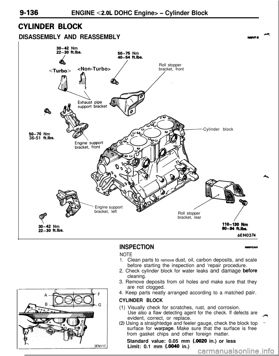
DISASSEMBLY AND REASSEMBLY,+Ymaw-030-42 Nm22-30 ft.lbs.
/50-75 Nm40-54 ft.lbs.
4a
r.‘?’
’ cRoll stopper
bracket, front/.50-76 Nm
36-51
ftlbs.
’ Engine support
bracket, left
Roll stopper
bracket, rear-Cylinder block32-42 Nm22-30
ftlbs.
110-130 Nm60-64 ft.lbs.6EN0374
INSPECTION
NOTE
1.Clean parts to remove dust, oil, carbon deposits, and scale
before starting the inspection and ‘repair procedure.
2. Check cylinder block for water leaks and damage
b&fore
cleaning.3. Remove deposits from oil holes and make sure that they
are not clogged.
4. Keep parts neatly arranged according to a matched pair.
CYLINDER BLOCK(1) Visually check for scratches, rust, and corrosion.
Use also a flaw detecting agent for the check. If defects areevident, correct, or replace.~
(2) Using a straightedge and feeler gauge, check the block top-surface for
warpage. Make sure that the surface is free
from gasket chips and other foreign matter.
Standard value: 0.05 mm
(4020 in.) or less
Limit: 0.1 mm
(AM40 in.)
Page 429 of 1216

INTAKE AND EXHAUST - Service Adjustment ProceduresII-7
w05A0155
h61
NO06061
NO0616 I
NO056(6) With the vacuum hose (black) closed when idling, apply
negative pressure and inspect the condition of the negative
pressure.
Engine stateDetonation sensor
connectorNormal state
,
ConnectionNegative pressureleaks.
Idling
DisconnectionNegative pressure
is maintained.
NOTEIf negative pressure is not normal, it can be assumed that there is amalfunction in the knock sensor circuit.(7) Turn off the ignition switch, and connect the connector of
the detonation sensor.
(8)Disconnect the (-) terminal of the battery for 10 seconds or
more.
NOTE
This erases the diagnosis memory of the detonation sensortrouble by disconnecting the detonation sensor connector.
SUPERCHARGING PRESSURE RELIEF SOLENOID
VALVE INSPECTIONNllGGAA
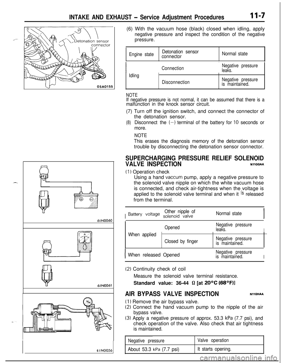
(1) Operation check
Using a hand
vaccum pump, apply a negative pressure to
the solenoid valve nipple on which the white vacuum hose
is connected, and check air-tightness when the voltage is
applied to the solenoid valve terminal and when it i‘s releasedfrom the terminal.
I
Other nipple ofBattery voile solenoid valveNormal state
OpenedNegative pressureleaks.IWhen applied
Closed by fingerNegative pressure
is maintained.
IWhen released OpenedNegative pressure
is maintained.
I
(2) Continuity check of coil
Measure the solenoid valve terminal resistance.Standard value: 36-44
fl [at 20°C (68OF)l
AIR BYPASS VALVE INSPECTIONNllGHAA
(1) Remove the air bypass valve.
(2) Connect the hand vacuum pump to the nipple of the air
bypass valve.
(3) Apply a negative pressure of approx. 53.3 kPa (7.7 psi), andcheck operation of the valve. Also check that air tightness
is maintained.
Negative pressure
About 53.3 kPa (7.7 psi)
Valve operation
It starts opening.
Page 444 of 1216

INTeKE AND EXHAUST - Turbocharger
13. DISCONNECTION OF POWER STEERING OIL PUMP
Disconnect the oil pump with hoses from the bracket.
NOTE
The removed power steering oil pump should be fastened
(by using rope, etc.) in a position that will not interfere with
the removal/installation of the turbocharger assembly.
I05AOO26
29. REMOVAL OF TURBOCHARGER ASSEMBLY
Remove the turbocharger assembly with the exhaust fitting,water
pipe A, water pipe 6 and the oil pipe attached to it.3B.REMOVAL OF OIL PIPE
CautionAfter disconnecting the oil pipe, take care that foreign
material does not enter the oil passage hole of the
turbocharger assembly.
INSPECTIONNllLCAC
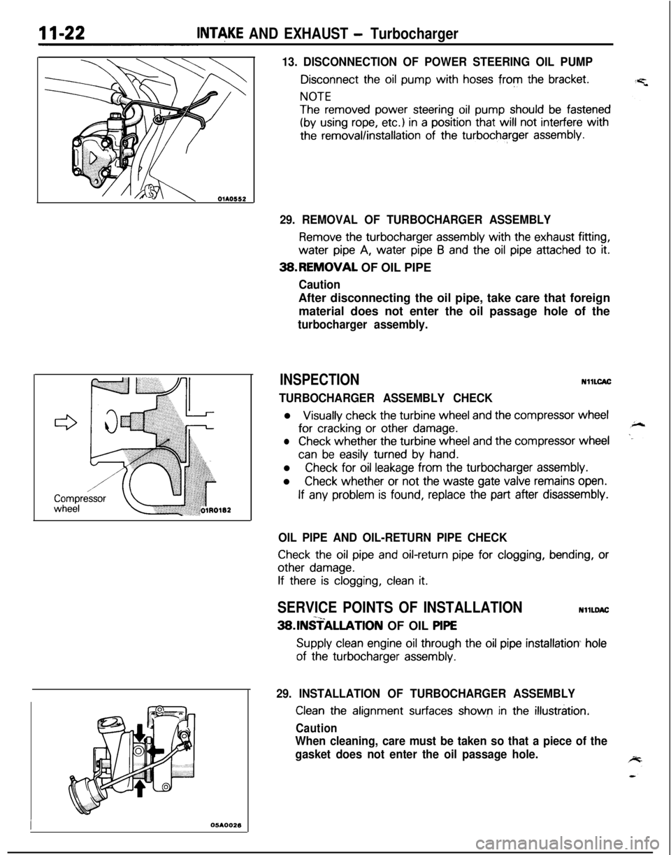
TURBOCHARGER ASSEMBLY CHECKl
Visually check the turbine wheel and the compressor wheelfor
cracking or other damage.
lCheck whether the turbine wheel and the compressor wheel
can be easily turned by hand.l
Check for oil leakage from the turbocharger assembly.l
Check whether or not the waste gate valve remains open.
If any problem is found, replace the part after disassembly.
OIL PIPE AND OIL-RETURN PIPE CHECK
Check the oil pipe and oil-return pipe for clogging, bending, or
other damage.
If there is clogging, clean it.
SERVICE POINTS OF INSTALLATIONNllLDAC-x_3SlNSTALLATlON OF OIL PlPE
Supply clean engine oil through the oil pipe installation hole
of the turbocharger assembly.
29. INSTALLATION OF TURBOCHARGER ASSEMBLY
Clean the alignment surfaces shown in the illustration.
Caution
When cleaning, care must be taken so that a piece of the
gasket does not enter the oil passage hole.
Page 446 of 1216

II-24INTAKE AND EXHAUST - TurbochargerSERVICE POINTS OF DISASSEMBLYNllLFAB
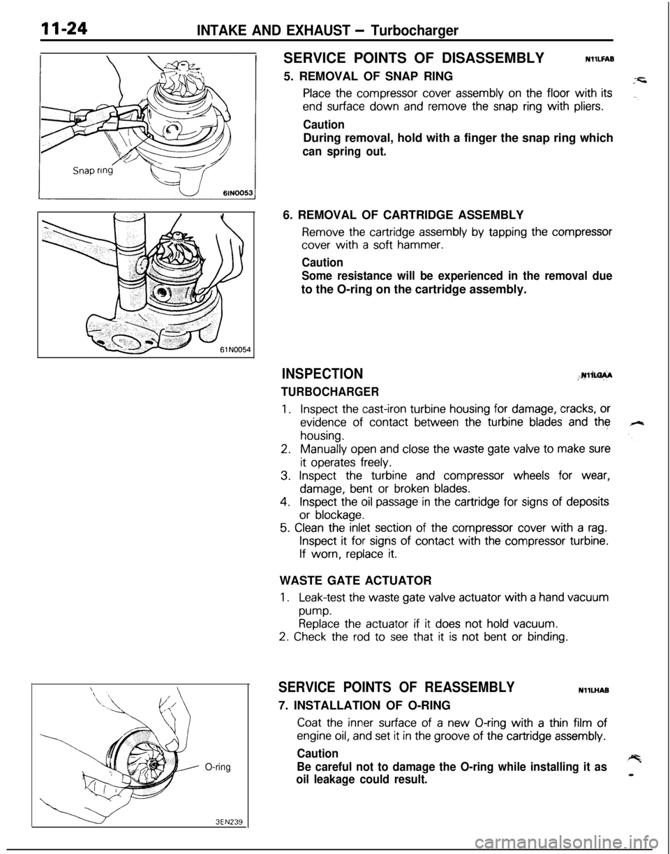
5. REMOVAL OF SNAP RING
Place the compressor cover assembly on the floor with its
end surface down and remove the snap ring with pliers.
CautionDuring removal, hold with a finger the snap ring which
can spring out.
O-ring
3EN2396. REMOVAL OF CARTRIDGE ASSEMBLY
Remove the cartridge assembly by tapping the compressor
cover with a soft hammer.
Caution
Some resistance will be experienced in the removal dueto the O-ring on the cartridge assembly.
INSPECTION;.rulim+A
TURBOCHARGER
1.Inspect the cast-iron turbine housing for damage, cracks, or
evidence of contact between the turbine blades and the
housing.
2.Manually open and close the waste gate valve to make sure
it operates freely.
3. Inspect the turbine and compressor wheels for wear,
damage, bent or broken blades.
4.Inspect the oil passage in the cartridge for signs of deposits
or blockage.
5. Clean the inlet section of the compressor cover with a rag.
Inspect it for signs of contact with the compressor turbine.
If worn, replace it.WASTE GATE ACTUATOR
1.Leak-test the waste gate valve actuator with a hand vacuum
pump.Replace the actuator if it does not hold vacuum.
2. Check the rod to see that it is not bent or binding.
SERVICE POINTS OF REASSEMBLYNllLHAB
7. INSTALLATION OF O-RING
Coat the inner surface of a new O-ring with a thin film of
engine oil, and set it in the groove of the cartridge assembly.
Caution
Be careful not to damage the O-ring while installing it as
oil leakage could result.
Page 448 of 1216

1 I-26INTAKE AND EXHAUST -Exhaust Manifold c 1.8L Engine>
EXHAUST MANIFOLD
< 1.8L Engine>
REMOVAL AND INSTALLATION
20-24 ft.lbs.
05A0135Removal steps’
1. Engine oil level gauge guide
2. O-ring3. Self locking nut4. Gasket5. Oxygen sensor6. Exhaust manifold cover (A)
7. Engine hanger8. Exhaust manifold9. Exhaust manifold gasket10. Exhaust manifold cover (B)
NOTE(1) Reverse the removal procedures to reinstall.(2) 4, : Refer to “Service Points of Removal”.(3) q : Non-reusable parts
SERVICE POINTS OF REMOVALNHNBAG5. REMOVAL OF OXYGEN SENSOR
Disconnect the connector of the oxygen sensor, and install
the special tool to the oxygen sensor.
Then, using an offset (box-end) wrench, remove the oxygen
sensor.
INSPECTIONNllNCALO
Check the following points; replace the part if a problem is
found.-y=.EXHAUST MANIFOLD
Check for damage or cracking of any part.EXHAUST MANIFOLD GASKET
Check for flaking or damage of the gasket.
O-ring
3EN239
or blockage.
5. Clean the inlet section of the compressor cover with a rag.
Inspect it for signs of contact with the compressor turbine.
If worn, replace it.WASTE GATE ACTUATOR
1.Leak-test the waste gate valve actuator with a hand vacuum
pump.
Replace the actuator if it does not hold vacuum.
2. Check the rod to see that it is not bent or binding.
SERVICE POINTS OF REASSEMBLYNllLHAB
7. INSTALLATION OF O-RING
Coat the inner surface of a new O-ring with a thin film of
engine oil, and set it in the groove of the cartridge assembly.
Caution+%
Be careful not to damage the O-ring while installing it as__
oil leakage could result.
Page 451 of 1216

INTAKE AND EXHAUST - Exhaust Manifold
OlAO552
05K55;,
SERVICE POINTS OF REMOVALNllNBAl
11. DISCONNECTION OF POWER STEERING OIL PUMP
:
Disconnect the oil pump with hoses from the bracket.
NOTE
The removed power steering oil pump should be fastened
(by using rope, etc.) in a position that will not interfere with
the removal/installation of the exhaust manifold.
lNSPECTlONNllNCALl
Check the following points; replace the part if a problem is
found.EXHAUST MANIFOLD
Check for damage or cracking of any part.EXHAUST MANIFOLD GASKET
Check for flaking or damage of the gasket.
SERVICE POINTS OF INSTALLATIONNllNQAG
18. INSTALLATION OF WATER PIPE (BI
Before installing to the water inlet pipe, apply machine oil to
the inner surface of the pipe flare.
Page 455 of 1216

14-IFUEL SYSTEM
CONTENTS
AUTO-CRUISECONTROLSYSTEM...........................................109AUTO-CRUISECONTROL.......................................................140SERVICEADJUSTMENTPROCEDURES..............................135Accelerator Cable, Throttle Cable and Auto-cruise
ControlCableInspectionandAdjustment........................136Auto-cruise
ControlSystemInspection.............................135lndrvrdualPartsInspection..................................................137SPECIFICATIONS.....................................................................109GeneralSpecifications.......................................................109ServiceSpecifications
.........................................................109Torque Specrfications..........................................................109TROUBLESHOOTING...............................................................110Auto-CruiseControlCircurt................................................128Auto-cruise
ControlComponentsLocation........................126Auto-cruise Control Related Harnesses
.............................125Check Chart
........................................................................114Input Check.........................................................................123Self-diagnosis
Check..........................................................121Troubleshootrng
Quick-referenceChart..............................110ENGINECONTROL.......................................................................105ENGINECONTROL..................................................................107--SERVICEADJUSTMENTPROCEDURES..............................106Accelerator Cable Inspection and Adjustment..................106Accelerator Switch Inspectron and Adjustment................106SPECIFICATIONS.....................................................................105Lubricants.............................................................................105Sealant.................................................................................105ServiceSpecifications
..........................................................105TorqueSpecifications..........................................................105TROUBLESHOOTING...............................................................105FUELSYSTEM..............................................................................2FUELFILTER............................................................................104FUELLINEANDVAPORLINE..............................................102FUEL PUMP, FUEL GAUGE UNIT ANDOVERFILL LIMITER(TWO-WAY VALVE)
Switch........................................................64Air Conditioner Power Relay
..............................................67Components
Location......................................................56
ControlRelay
.................................................................66EGRControlSolenoidValve...............................................67EGRTemperatureSensor..................................................64Engine Coolant Temperature Sensor
.................................62IdlePosrtionSwitch
...........................................................63IdleSpeedControlServo
.............................
....................65InhibitorSwitch....................................................................65hjeCtOrS................................................................................65IntakeAirTemperatureSensor..........................................6’2MalfunctionlndtcatorLight
..........................................58MotorPosition
Sensor................................................63OxygenSensor
.................................................................64Power Steering 011 Pressure Swatch...........................65PowerTransistor
................................................................67PurgeControlSolenoidValve.........................................67
Self-Diagnosis.......................................................................
ThrottlePositronSensor.....................................................
Vehicle Speed Sensor.........................................................MPI
SYSTEMINSPECTION<2.0L DOHCEngine>...........Air Conditioner Power Relay..............................................
Arr Conditioner Swatch........................................................
Components Location
.........................................................
Control
Relay.......................................................................
EGR Control Solenoid Valve...............................................
EGR Temperature Sensor
...................................................
Engine Coolant Temperature Sensor
.................................Fuel Pressure Control Valve...............................................
Idle Position Switch
............................................................
Idle
SpeedControlServo...................................................Injectors
................................................................................
Intake Air Temperature Sensor..........................................
Malfunction Indicator Light.................................................
Oxygen Sensor
....................................................................
Power
Steering
OilPressureSwitch.................................Power Transistor
.................................................................
Purge Control Solenoid Valve.............................................
Self-Diaanosis.......................................................................
58
63
2382
79
688182
79
7682
77
79
79
76
727879
82
8273ThrottletiPosition Sensor
.....................................................77Vehicle Speed Sensor
.........................................................79SERVICE ADJUSTMENT PROCEDURES<1.8L Engine>........................................................................41Curb Idle Speed Inspection
................................................41EGR Valve Control Vacuum Check....................................47Fuel Pressure Test
..............................................................44Fuel Pump Operation Check
..............................................44Idle Speed Control and Throttle Position
Sensor Adjustment
..............................................................
41Purge Port Vacuum Check
.................................................47Release of Residual Pressure from
High Pressure Fuel Hose
...................................................
44Throttle
Body(Throttle Valve Area)Cleaning....................43SERVICE ADJUSTMENT PROCEDURES<2.0LDOHCEngine>............................................................48Basic Idle Speed Adjustment
.............................................
48
Curb Idle Speed Inspection
................................................48EGR Valve Control Vacuum Check....................................55Fuel Pressure Test
..............................................................52Fuel Pump Operation Check
..............................................51Idle Position Switch Adjustment........................................52Purge Port Vacuum Check
.................................................55Release of Residual Pressure from
High Pressure Fuel Hose
...................................................51Throttle Body (Throttle Valve Area) Cleaning....................51ThrottlePositionSensorAdjustment.................................50SPECIALTOOLS......................................................................6SPECIFICATIONS.....................................................................2GeneralSpecifications.........................................................2Sealant and Adhesive
.........................................................5Service Specifications
..........................................................4Torque Specifications
..........................................................5THROlTLEBODY<1.8LEngine>........................................85THROlTLE BODY <2.0L DOHC Engine>............................89TROUBLESHOOTING...............................................................6
Page 460 of 1216

14-6FUEL SYSTEM - Special Tools/Troubleshooting
SPECIAL TOOLSNWA-B
Number
M D998742
Name
Hose adapter
Usel Measurement
of fuel pressure (to be usedtogether
with MD9987091
MD998709Adapter hosel Measurement of fuel pressure (to be usedtogether
with MD9987421
TROUBLESHOOTING
When checking and correcting engine troubles, it is
important to start with inspection of the basic
systems.
In case you have such troubles as (1) engine start
failure, (2) rough idling or (3) poor acceleration,
therefore, you should first check the following basic
systems:
(1) Power supply
0 Batteryl
Fusible linkl
Fuse
(2) Body ground
(3) Fuel supplyl
Fuel linel
Fuel filter
l
Fuel pump
N14EBBH
(4) Ignition systeml
Spark plugsl
High tension cablel Distributor
<1.8L Engine>
l
Crank angle sensor <2.0L DOHC Engine>
0 Ignition coil
(5) Emission control systeml
Crankcase ventilation systeml
Exhaust gas recirculation systeml
Vacuum leak
(6) Others
0 Ignition timing
l
Idle speed
Troubles with the MPI system are often caused by
poor contact of harness connector. It is, therefore,
important to check harness connector contact.