Page 536 of 1216

14-82FUEL SYSTEM - MPI System Inspection <2.0L DOHC Engine>
\ \\I \3FUO352
,\ \
\I \3FUO353
,\ ‘\R/
\ \\I \3FUo354
POWER TRANSISTORRefer to GROUP 8
- Ignition System
NlIAcQAl
a-4
AIR CONDITIONER POWER RELAYN14NCl.a -Refer to GROUP 24
- Air Conditioner.
PURGE CONTROL SOLENOID VALVEN14RCKARefer to GROUP 25
- Evaporative Emission Control System.
EGR CONTROL SOLENOID VALVE
N14NCURefer to GROUP 25
- Exhaust Gas Recirculation System.
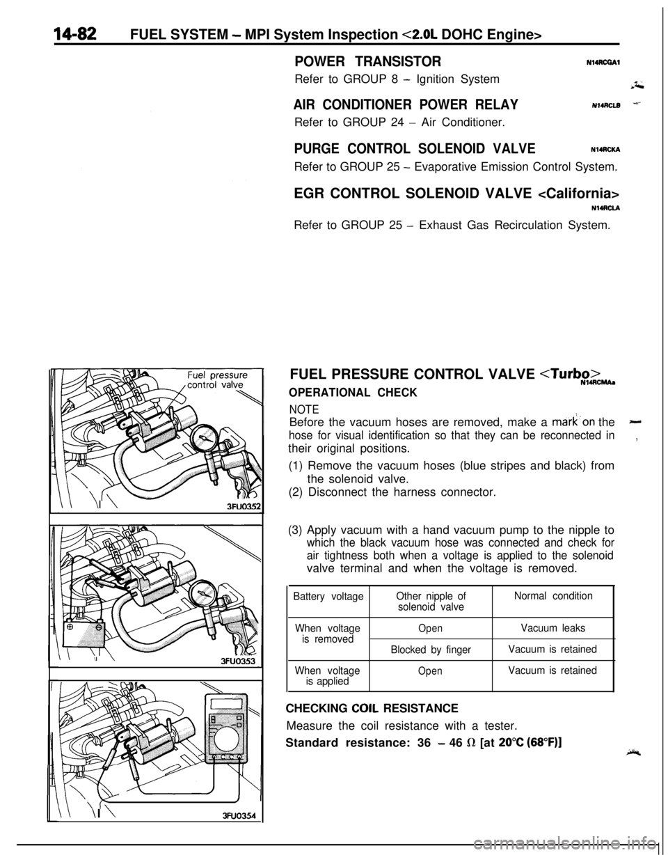
FUEL PRESSURE CONTROL VALVE
OPERATIONAL CHECK
NOTEBefore the vacuum hoses are removed, make a mark’on the
-
hose for visual identification so that they can be reconnected in,their original positions.
(1) Remove the vacuum hoses (blue stripes and black) from
the solenoid valve.
(2) Disconnect the harness connector.
(3) Apply vacuum with a hand vacuum pump to the nipple to
which the black vacuum hose was connected and check for
air tightness both when a voltage is applied to the solenoidvalve terminal and when the voltage is removed.
Battery voltageOther nipple of
solenoid valveNormal condition
When voltage
is removed
When voltage
is applied
OpenVacuum leaks
Blocked by fingerVacuum is retained
OpenVacuum is retainedCHECKING
COIL RESISTANCE
Measure the coil resistance with a tester.
Standard resistance: 36
- 46 R [at 20°C (68”F)]
Page 538 of 1216

14-84FUEL SYSTEM - Injector
03*0095
Delivery pipe03A0095-SERVICE POINTS OF REMOVAL
H4s0m1‘~
3.DISCONNECTION OF THE HIGH PRESSURE FlJFL HOSE /;;
Bleed the residual pressure within the fuel pipe line’& as to~prevent the flow of fuel.
For information concerning the method to be folfowed for
bleeding the residual pressure, refer to
P.14-44.Caution
Cover the hose connection with rags to prevent splash,
of fuel that could be caused by some residual pressure
in the fuel pipe line.
12. REMOVAL OF DELIVERY PIPE/ 15. INJECTOR
Remove the deliver-y pipe (with the injectors attached to it).Caution
Care must be taken, when removing the delivery pipe,
not to drop the injector.
INSPEiZTION
INJECTORS
N14NGAA
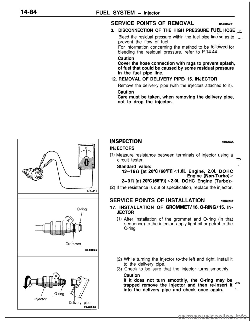
(1) Measure resistance between terminals of injector using a
circuit tester.+-%Standard value:
/13-1652 [at
20°C (68”F)] <1.8L Engine, 2.0L DOHC
Engine
(NoniTurbo)>
2-3Q [at 20°C (68”F)] <2.0L DOHC Engine (Turbo)>
(2) If the resistance is out of specification, replace the injector.
SERVICE POINTS OF INSTALLATION
N14SDAEl’17. INSTALLATION OF
GROMMET/lG. 0-RINGI15. IN-
JECTOR
(I) After installation of the grommet and O-ring (in that
sequence) to the injector, apply light oil or petrol to the
O-ring.(2) While turning the injector to.the left and right, install it
to the delivery pipe.
(3) Check to be sure that the injector turns smoothly.
Caution
If it does not turn smoothly, the O-ring may be
~trapped remove the injector and then re-insert it
into the delivery pipe and check once again.
L
Page 601 of 1216

PROPELLER SHAFT - Propeller Shaft
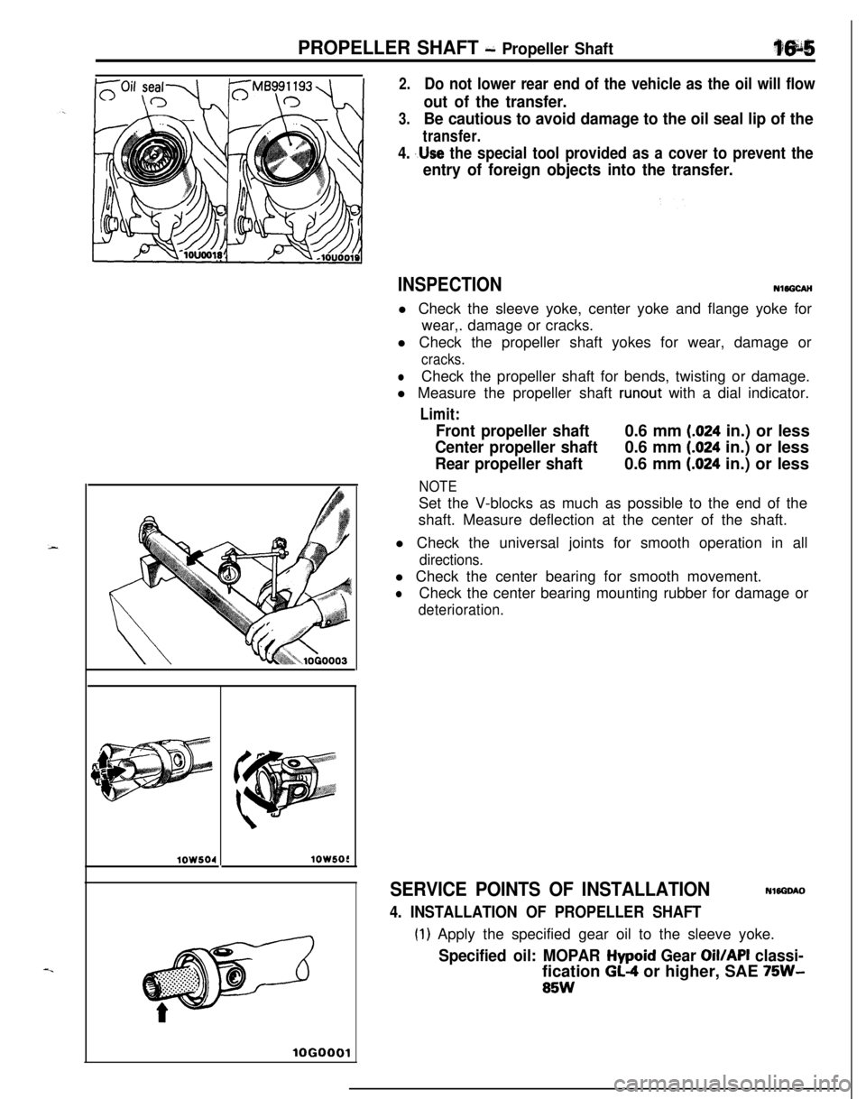
2.Do not lower rear end of the vehicle as the oil will flow
out of the transfer.
3.Be cautious to avoid damage to the oil seal lip of the
transfer.
4. ,.Use the special tool provided as a cover to prevent the
entry of foreign objects into the transfer.
lOW504lOW5OC
lOGO
INSPECTIONNl5GCAH
l Check the sleeve yoke, center yoke and flange yoke for
wear,. damage or cracks.
l Check the propeller shaft yokes for wear, damage or
cracks.
lCheck the propeller shaft for bends, twisting or damage.
l Measure the propeller shaft
runout with a dial indicator.
Limit:
Front propeller shaft0.6 mm (.024 in.) or less
Center propeller shaft0.6 mm (.024 in.) or less
Rear propeller shaft0.6 mm (.024 in.) or less
NOTESet the V-blocks as much as possible to the end of the
shaft. Measure deflection at the center of the shaft.
l Check the universal joints for smooth operation in all
directions.l Check the center bearing for smooth movement.
lCheck the center bearing mounting rubber for damage or
deterioration.
SERVICE POINTS OF INSTALLATIONNWGOAO
4. INSTALLATION OF PROPELLER SHAFT
(1) Apply the specified gear oil to the sleeve yoke.
Specified oil: MOPAR Hypoid Gear Oil/API classi-fication
GL-4 or higher, SAE 75W-
85W
Page 613 of 1216

Special Tools/Troubleshooting/REAR SUSPENSION - Service Adjujltment Procedures
SPECIAL TOOLN17DA.A
ToolNumberName1 Use1
L-451 4
Spring compressorRemoval and installation of the coil spring
bodyTROUBLESHOOTINGNI’IEA-A
Symptom
Squeaks or other
abnormal noiseProbable cause
Loose rear suspension installation bolts and nuts
Malfunction of shock absorber
Worn bushings
Remedy
Retighten
Replace
Poor rideExcessive tire inflation pressure
Malfunction of shock absorberWeak or broken springs
Adjust the pressure
Replace
Body tiltingWeak or deteriorated bushings
Weak or broken springs
Replace
SERVICE ADJUSTMENT PROCEDURES
REAR WHEEL ALIGNMENT INSPECTIONN17FAAC
The rear suspension assembly must be free of worn, loosen or
damaged parts prior to measurement of rear wheel alignment.
Standard value:
Toe-in (Left-right difference)
Of3 mm (Of.118 in.)
Camber-45’ + 30’
NOTEThe rear wheel alignment is set at the factory and cannot be
adjusted.If toe-in or camber is not within the standard value, replace
bent or damaged parts.
WHEEL BEARING END PLAY ADJUSTMENT,7FBA0
1.Inspect the play of the bearings while the vehicle is jacked
up and resting on floor jack.
2.Remove the hub cap and then release the parking brake.
3. Remove the caliper assembly and the brake disc.
4. Check the bearing’s end play.
Place a dial gauge against the hub surface; then move the
hub in the axial direction and check whether or not there isend play.
Limit: 0.01 mm
(.004 in.) or less
NOTE12AO531If the limit value is exceeded, the lock nut should be
tightened to the specified torque and check the end play
again.
5.Replace the rear hub bearing unit if an adjustment cannot
be made to within the limit.
Page 619 of 1216
REAR SUSPENSION - ‘Shock Absorber Asset&y“fg$
DISASSEMBLY AND REASSEMBLYNI’IOM-A
Disassembly steps
+e ~~ ?. Piston rod tightening nut
2. Washer
3. Upper bushing (A)
e+ 4. Bracket assembly
5. Upper spring pad
6. Upper bushing
(B)7. Collarl + 8. Cup assembly
l + 9. Dust cover
10. Bump rubber
l 4 11. Coil spring12. Shock absorber
NOTE(1) Reverse the disassembly procedures to reassemble.(2) +I) : Refer to “Service Points of Disassembly”.(3)~~ : Refer to “Service Points of Reassembly”.(4)q : Non-reusable parts
\@3----612AO328
12Y626
SERVICE POINTS OF DISASSEMBLYNI’IGNAAI
1. REMOVAL OF PISTON ROD TIGHTENING NUT(1) Before removing the piston rod tightening nut,
compress the coil spring using the special tools.
CautionDo not use an air tool to tighten the bolt of the
special tool.(2) While holding the piston rod, remove the piston rod
tightening nut.
INSPECTION
Nl?GOAAll Check the rubber parts for damage.
lCheck the coil springs for crack, damage or deterioration.
Page 625 of 1216
c.
REAR SUSPENSION - Rear Axle’ Hub1~74s9. REMOVAL OF REAR ROTOR
z:.*It
Slit
14A0419Caution
Care must be taken not to
‘scratch-,‘,or other&%&damage the teeth of the rotor. The
.rotor must never be
dropped. If the teeth of the rotor are chipped, resulting
in a deformation of the rotor, it will not be-able to
accurately detect the wheel rotation speed’,
and the
system will not function normally.
10. REMOVAL OF REAR HUB BEARING UNIT
NOTEIRear hub bearing unit cannot be disassembled.,
INSPECTIONNllMCABl Check the oil seal for crack or damage.
l Check the rear hub for wear or damage.
SERVICE POINTS OF INSTALLATIONN17MDAG
IO. INSTALLATION OF REAR HUB BEARING UNJTPress inner race further until inner race contacts with
spindle end.
6. INSTALLATION OF WHEEL BEARING, NUT
After tightening the wheel bearing ‘nut, align with the
spindle’s indentation and crimp.
1. INSTALLATION OF REAR SPEED SENSOR
ABS>Refer to GROUP
5-Wheel Speed Sensor.
Page 643 of 1216
REAR SUSPENSION - Shock Absorber Assemblv
DISASSEMBLY AND REASSEMBLY
Nl’IGM-Bnut Piston rod tightening
Washer
Upper bushing
(A)Bracket assembly
Spring pad
Upper bushing
(8)CollarCup assembly
Dust cover
Bump rubber
Coil spring
Shock absorber
20-25 Nm1210360
SERVICE POINTS OF DISASSEMBLYN17GNAA22. REMOVAL OF PISTON ROD TIGHTENING NUT
(1) Before removing the piston rod tightening nut com-
press the coil spring using the special tools.
Caution
Do not use an air tool to tighten the bolt of the
special tool.
(2) While holding the piston rod, remove the piston rod
tightening nut.
INSPECTIONN17GOAA2l Check the rubber parts for damage.
l
Check the coil springs for crack, damage or deterioration.
Page 649 of 1216

STEERING
CONTENTSNISAA-
MANUAL STEERINGGEAR BOX.................21
POWER STEERINGGEAR BOX...................
28
POWER STEERING
HOSES........................
46
POWER STEERING OIL PUMP....................39
SERVICE ADJUSTMENT PROCEDURES
>...........................7
Steering Angle Check..............................7
Steering Wheel Centering.........................8
Steering Wheel Free Play Check.............:..7Tie Rod End Ball Joint Starting Torque
Check..................................................8Tie Rod End Ball Joint Variation Check
(Shaft direction).....................................7
SERVICE ADJUSTMENT PROCEDURES
< POWER STEERING >.............................
10
Bleeding...............................................13Fluid Level Check...................................
12
Fluid Replacement..................................12
i;,
Oil Pressure Switch Check........................15
Oil Pump Pressure Test...........................14
Stationary Steering Effort Check.................11Steering Angle Check..............................
10
Steering Wheel Centering.........................1 1
Steering Wheel Free Play Check................10Steering Wheel Return to Center Check.......
11Tie Rod End Ball Joint Starting Torque
Check..................................................10Tie Rod End Bail Joint Variation Check
(Shaft direction).....................................10
V-Belt Tension Check..............................12
SPECIAL TOOLS......................................6
SPECIFICATIONS.....................................2;
General Specifications..............................2
Lubricants.............................................5
Sealants and Adhesives............................5
Service Specifications.............‘................2
Torque Specifications,. . . . . . . . . . . . . . . . . ..*..........3
STEERING WHEEL AND SHAFT.................. 16