1991 MITSUBISHI ECLIPSE check oil
[x] Cancel search: check oilPage 741 of 1216

MANUAL TRANSAXLE
Springprotrusion2010018TFM0021
MD998320/
SPEED GEARS
lCheck the bevel gear and clutch gear teeth for damage and
wear.l Check the synchronizer cone for rough
surface, damage
and wear.
lCheck the gear ‘bore and front and rear ends for damage
and wear.
SERVICE POINTS OF REASSEMBLY
12. INSTALLATlON OF SYNCHRONIZER SPRING
Install the synchronizer spring so that its protrusion fits intothe groove in the synchronizer key. Make sure that the
protrusions in the front and rear springs are not in the
groove of the same key.
11. INSTALLATION OF 3RD-4TH SPEED SYNCHRONIZER
ASSEMBLY(1) Install the synchronizer assembly so that the part that
has the small round indentation is in the oil groove at
the hub end.
NOTEIf the installation is in the opposite way, press-in might
not be possible. This is because the edge of the hub
inner diameter
spline at the part that has the small
round indentation is made to facilitate pressing in.
(2) Press the
3rd-4th speed synchronizer assembly onto
the input shaft using the special tool as illustrated.
Caution
When installing the synchronizer assembly, make
sure that three synchronizer keys are seated cor-rectly in respective grooves of the synchronizer
ring.(3) Check the
3rd speed gear rotates smoothly.
9. INSTALLATION OF BEARING SLEEVEUse the special tool as illustrated.
Page 747 of 1216

MANUAL TRANSAXLE
2010018
2ndgearTFM0024
MD998320
20105f
SPEED GEARS
lCheck the bevel gear and clutch gear teeth for damage andw.wear.l Check the synchronizer cone for rough surface, damage
and wear.
lCheck the gear bore and front and rear ends for damage
and wear.
SERVICE POINTS OF REASSEMBLY
13. INSTALLATION OF SYNCHRONIZER SPRINGAssemble the synchronizer spring so that its projection
may be engaged in the groove of the synchronizer key.
Take care to prevent the projections of the front and rear
spring from sitting in the groove of the same key.
12. INSTALLATION OF 3RD-4TH SPEED SYNCHRONIZER
ASSEMBLY
(1) Install the synchronizer assembly so that the part that
has the small round indentation is in the oil groove at
the hub end.
NOTEIf the installation is in the opposite way, press-in might
not be possible. This is because the edge of the hub
inner diameter spline at the part that has the small
round indentation is made to facilitate pressing in.
(2) Press the
3rd-4th speed synchronizer assembly onto
the input shaft using the special tool as illustrated.
Caution
When installing the synchronizer assembly, make
sure that three synchronizer keys are seated cor-rectly in respective grooves of the synchronizer
ring.(3) Check the
3rd speed gear rotates smoothly.
10. INSTALLATION OF BEARING SLEEVEUse the special tool as illustrated.
j
Page 776 of 1216

21-82MANUAL TRANSAXLE
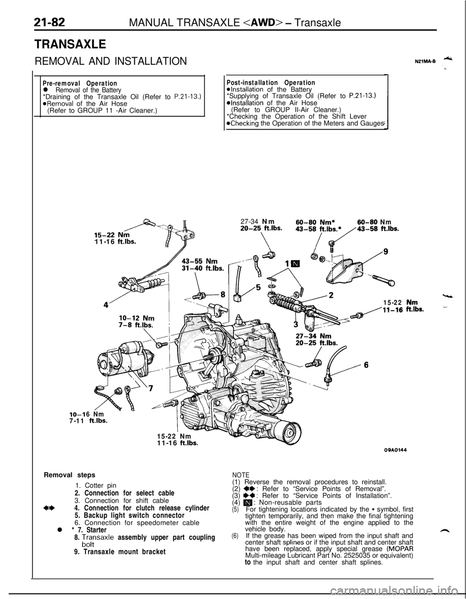
TRANSAXLE
REMOVAL AND INSTALLATION
Pre-removal Operationl Removal of the Battery*Draining of the Transaxle Oil (Refer to P.Zl-13.)
@Removal of the Air Hose
(Refer to GROUP 11 -Air Cleaner.)IO-1
7-1111-16
ftlbs.
Post-installation Operation@Installation of the Battery
*Supplying of Transaxle Oil (Refer to P.21-13.)*Installation of the Air Hose
(Refer to GROUP II-Air Cleaner.)
*Checking the Operation of the Shift Lever
@Checking the Operation of the Meters and Gauges
27-34 Nm
60-60 Nm*60-80 Nm20-25 ft.lbs.
\
43-58/t.,b~43-58 ft.lbs.
15-22
6 Nm
ftlbs.
15-22 Nm
vt11-16
ft.lbs.Removal steps
1. Cotter pin
2. Connection for select cable
3. Connection for shift cable
*I)4. Connection for clutch release cylinder
5. Backup light switch connector
6. Connection for speedometer cable
l * 7. Starter
8.
A;;saxle assembly upper part coupling
9. Transaxle mount bracket
NZlMA-B -
,“rr,s.
09AOl44
NOTE(1) Reverse the removal procedures to reinstall.
(2)
+e : Refer to “Service Points of Removal”.
(3) I)+ : Refer to “Service Points of Installation”.
(4) m : Non-reusable parts(5)For tightening locations indicated by the * symbol, first
tighten temporarily, and then make the final tightening
with the entire weight of the engine applied to the
(6)vehicle body.
If the grease has been wiped from the input shaft and
center shaft splines or if the input shaft and center shaft
have been replaced, apply special grease
(MOPARMulti-mileage Lubricant Part No. 2525035 or equivalent)
to the input shaft and center shaft splines.
Page 812 of 1216

MANUAL TRANSAXLE
vear210018
Springprotrusion
Key
201001::
TFM0023
SPEED GEARSl Check the bevel and clutch gear teeth for damage and
.6
wear.l Check the synchronizer cone for rough surfaces, damage,
-‘and wear.
lCheck the gear bore and front and rear ends for damage
and wear.
SERVICE POlNTS OF REASSEMBLY18. INSTALLATION OF SUB
GEAR/17. CONE SPRING/16. SNAP RING
Install the sub gear and cone spring to 3rd speed gear, andthen install the snap ring.
NOTE
Be sure that the cone spring is installed so that it is facing inthe correct direction.
10. INSTALLATION OF SYNCHRONIZER SPRINGS
(1) Install the synchronizer spring so that its protrusion fits
into the groove in synchronizer key. Make sure that the
protrusions in the front and rear springs are not in the
in,groove of the same key.
9. INSTALLATION OF
3RD-4TH SPEED SYNCHRONIZER
ASSEMBLY
(1) Install the synchronizer assembly so that the part that
has the small round indentation is in the oil groove at
the hub end.
NOTEIf the installation is in the opposite way, press-in might
not be possible. This is because the edge of the hub
inner diameter
spline at the part that has the small
round indentation is made to facilitate pressing in.
(2) Using the special tools, press-fit the
3rd-4th speed
synchronizer assembly over the input shaft.
Caution
1. When installing the synchronizer assembly,
make sure that the three synchronizer keys are
seated correctly in their respective grooves in
the synchronizer ring.
h2. After installing the synchronizer assembly, --
check to see if the
3rd speed gear rotates
smoothly.
Page 824 of 1216

21-130MANUAL TRANSAXLE
SERVICE POINTS OF REASSEMBLY8. INSTALLATION OF OIL SEAL
Using the special tool, install the oil sea
jP,
II..-67. INSTALLATION OF SPACER
Install the spacer which has been used so far
3. INSTALLATION OF SPACER
Install the spacer which has been used so far
INSPECTIONDRIVE BEVEL GEAR ASSEMBLY
Using the special tools, check to see if the turning drive torque
of the drive bevel gear is up to specification.
Standard value: 1.7
- 2.5 Nm (1.23 - 1.81 ft.lbs.)Caution
1.If the turning drive torque is out of specification, adjust
by using adjusting spacers.
2.Select spacers of nearly same thickness on both sides.
h
Page 860 of 1216

21-166AUTOMATIC TRANSAXLE - SDecifications
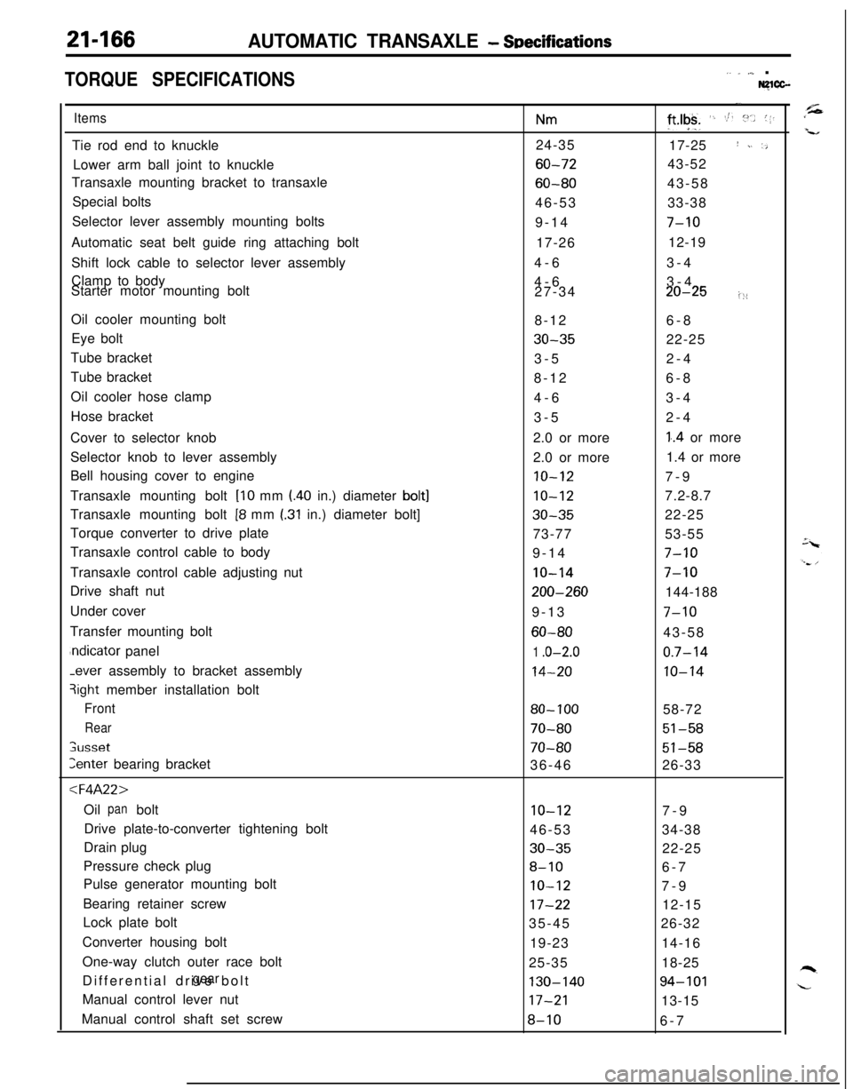
TORQUE SPECIFICATIONS,. _ ,,,_ .Nglcc-
ItemsTie rod end to knuckle
Lower arm ball joint to knuckle
Transaxle mounting bracket to transaxle
Special bolts
Selector lever assembly mounting bolts
Automatic seat belt guide ring attaching bolt
Shift lock cable to selector lever assembly
Clamp to body
Starter motor mounting bolt
Oil cooler mounting bolt
Eye bolt
Tube bracket
Tube bracket
Oil cooler hose clamp
Hose bracket
Cover to selector knob
Selector knob to lever assembly
Bell housing cover to engine
Transaxle mounting bolt
[lo mm l.40 in.) diameter bolt]Transaxle mounting bolt
[8 mm I.31 in.) diameter bolt]
Torque converter to drive plate
Transaxle control cable to body
Transaxle control cable adjusting nut
Drive shaft nut
Under cover
Transfer mounting boltndicator panel-ever assembly to bracket assembly
3ight member installation bolt
Front
Rear
;usset
Zenter bearing bracket
:l=4A22>Oil bolt
panDrive plate-to-converter tightening bolt
Drain plug
Pressure check plug
Pulse generator mounting bolt
Bearing retainer screw
Lock plate bolt
Converter housing bolt
One-way clutch outer race bolt
Differential drive bolt
gearManual control lever nut
Manual control shaft set screw
Nm24-35
60-72
60-8046-53
9-14
17-26
4-6
4-6
27-34
8-12
30-353-5
8-12
4-6
3-5
2.0 or more
2.0 or more
10-12
10-12
30-3573-77
9-14
IO-14
200-2609-13
60-80
1 .o-2.0
14-20
80- 100
70-80
70-8036-46
10-1246-53
30-35
8-10
IO-12
17-2235-45
19-23
25-35
130-14017-21
8-10
-.
ft*lgk+ ‘. St. :“.. (1.17-25
I ~. ‘,43-52
43-58
33-38
7-1012-19
3-4
3-4
20-25i::6-8
22-25
2-4
6-8
3-4
2-4
1..4 or more
1.4 or more
7-9
7.2-8.7
22-25
53-55
7-10
7-10144-188
7-1043-58
0.7-14
10-1458-72
51-58
51-5826-33
7-9
34-38
22-25
6-7
7-9
12-15
26-32
14-16
18-25
94-10113-15
6-7
Page 861 of 1216

AUTOMATIC TRANSAXLE - SeecificdionsItems
Inhibitor switch
Sprag rod support bolt
Pump housing-to-reaction shaft support
bolt
Oil assembly mounting bolt
pumpValve body bolt
Valve body assembly mounting bolt
Oil filter bolt
Speedometer sleeve locking plate bolt
End clutch cover
Kickdown lock nut
< F4A33.W4A33 >Air exhaust plug
Center bearing retainer stopper bolt
Differential drive bolt
gearDifferential front bearing bolt
capDifferential rear bearing retainer bolt
End clutch cover bolt
Front bearing retainer bolt
gearIdler shaft lock bolt
Inhibitor switch bolt
Kickdown servo lock nut
Manual control lever nut
Manual control shaft set screw
Oil drain bolt
Oil filter bolt
Oil level guide bolt
gaugeOil bolt
panOil check plug
pressureOil assembly mounting bolt
pumpOil pump bolt
Output bearing retainer bolt
Output flange bearing retainer bolt
Nm
IO-12
20-27
10-1215-22
4-6
10-125-7
3-5
6-8
25-32
30-354-6
70-80
10-12
130-140
60-80
30-40
10-1243-55
10-1231-44
IO-1225-32
17-21
8-10
30-355-7
20-27
10-124-6
19-23
10-12
20-2717-22
,I
‘ft.lbs.
7-915-19
,,
7-911-15
3-4
7-94-5
2-4
5-6
18-23
22-25
3-4
51-57
7-9
94-10143-58
22-29
7-9
32-39
7-922-32
7-9
18-23
12-15
6-7
-_22-25
4-5
15-19
7-93-4
13-17
7-9
15-19
12-16"/Parking rod support bolt
20-2715-19Pulse generator bolt
IO-127-9Roll stopper bracket bolt
43-55
32-39
'Shift control cable bracket bolt
20-2715-19Speedometer gear locking plate bolt
4-6
3-4
Transaxle mount bracket bolt
60-80$-,58Valve body assembly mounting bolt
10-127-9
Valve body bolt
4-6
3-4
-.
Page 869 of 1216

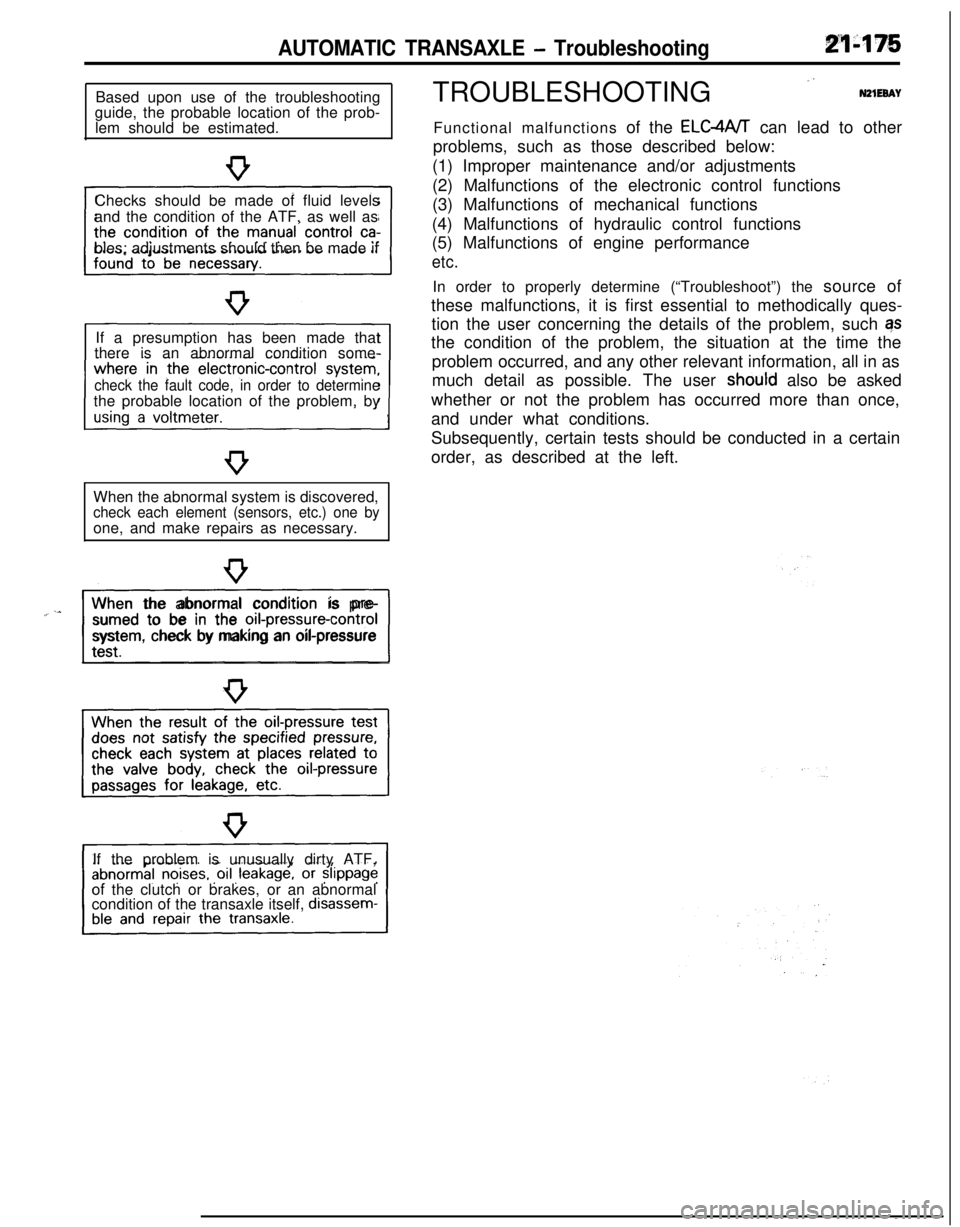
AUTOMATIC TRANSAXLE - TroubleshootingBased upon use of the troubleshooting
guide, the probable location of the prob-
lem should be estimated.
Checks should be made of fluid levels
and the condition of the ATF, as well as
bles; adjustments should then be made if
If a presumption has been made that
there is an abnormal condition some-
check the fault code, in order to determinethe probable location of the problem, by
When the abnormal system is discovered,
check each element (sensors, etc.) one byone, and make repairs as necessary.
“~^II_When the abnormal condition is pre-
sumed to be in the
orI-pressure-controlsystem, check by making an oil-pressure
If the problem is unusually dirty ATF,
of the clutch or brakes, or an abnormal
condition of the transaxle itself,
disassem-TROUBLESHOOTING
”N21EeAYFunctional malfunctions of the ELC4A/T can lead to other
problems, such as those described below:
(1) Improper maintenance and/or adjustments
(2) Malfunctions of the electronic control functions
(3) Malfunctions of mechanical functions
(4) Malfunctions of hydraulic control functions
(5) Malfunctions of engine performance
etc.In order to properly determine (“Troubleshoot”) the source of
these malfunctions, it is first essential to methodically ques-
tion the user concerning the details of the problem, such qs
the condition of the problem, the situation at the time the
problem occurred, and any other relevant information, all in as
much detail as possible. The user
shoutd also be asked
whether or not the problem has occurred more than once,
and under what conditions.
Subsequently, certain tests should be conducted in a certain
order, as described at the left.