Page 908 of 1216

21-214AUTOMATIC TRANSAXLE - Service Adjustment Procedures
'50157
F4
1
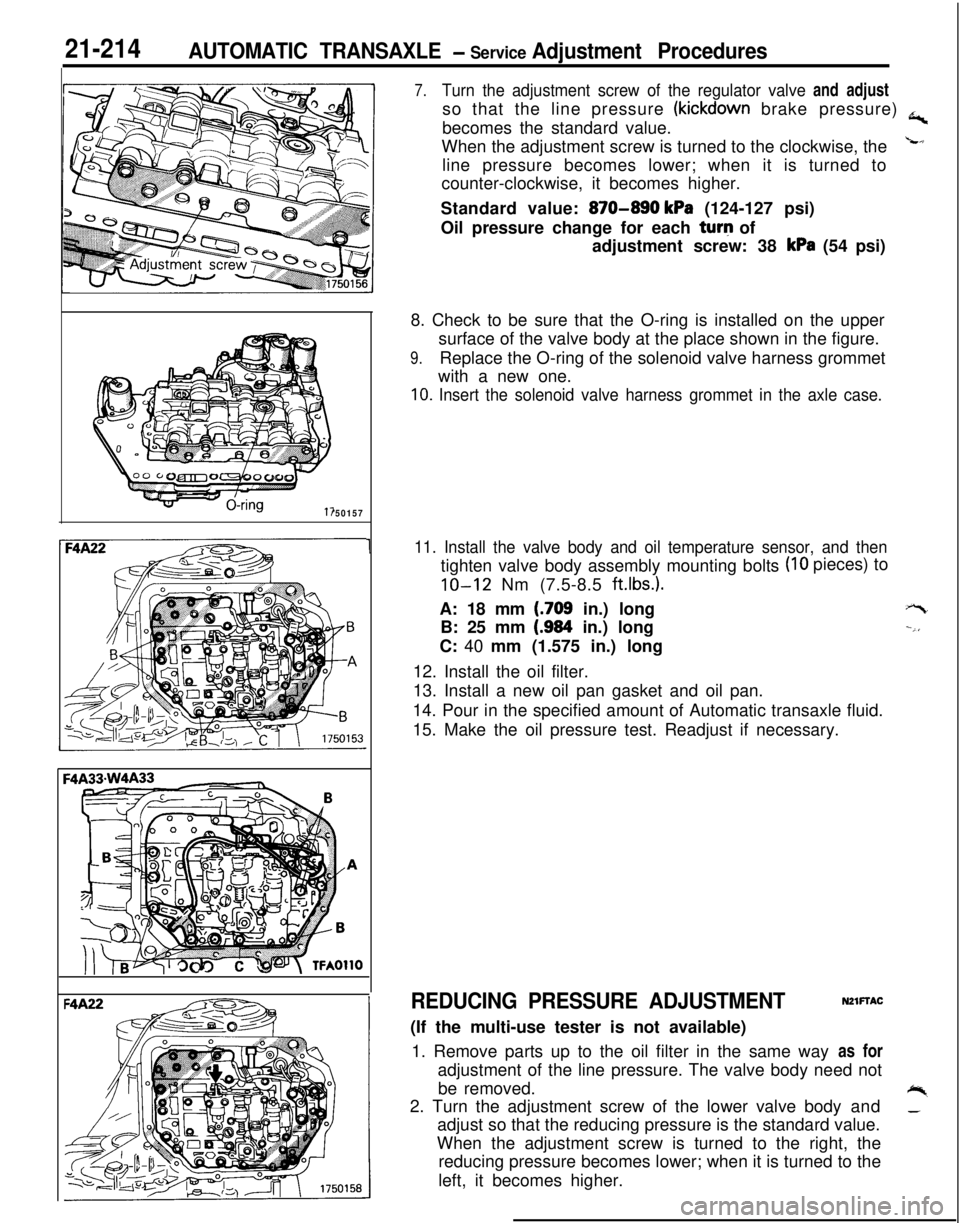
7.Turn the adjustment screw of the regulator valve and adjustso that the line pressure
(kickdown brake pressure) a,becomes the standard value.
When the adjustment screw is turned to the clockwise, the
Lline pressure becomes lower; when it is turned to
counter-clockwise, it becomes higher.
Standard value:
870-890 kPa (124-127 psi)
Oil pressure change for each turq of
adjustment screw: 38
kPa (54 psi)
8. Check to be sure that the O-ring is installed on the upper
surface of the valve body at the place shown in the figure.
9.Replace the O-ring of the solenoid valve harness grommet
with a new one.
10. Insert the solenoid valve harness grommet in the axle case.
11. Install the valve body and oil temperature sensor, and then
(IO pieces) to
tighten valve body assembly mounting bolts
IO-12 Nm (7.5-8.5 ft.lbs.).A: 18 mm
(.709 in.) long
B: 25 mm
(.984 in.) long
C: 40 mm (1.575 in.) long
12. Install the oil filter.
13. Install a new oil pan gasket and oil pan.
14. Pour in the specified amount of Automatic transaxle fluid.
15. Make the oil pressure test. Readjust if necessary.
+-t
--,,
REDUCING PRESSURE ADJUSTMENTNZlFTAC(If the multi-use tester is not available)
1. Remove parts up to the oil filter in the same way as for
adjustment of the line pressure. The valve body need not
be removed.
+%2. Turn the adjustment screw of the lower valve body and_adjust so that the reducing pressure is the standard value.
When the adjustment screw is turned to the right, the
reducing pressure becomes lower; when it is turned to the
left, it becomes higher.
Page 917 of 1216
AUTOMATIC TRANSAXLE - Transaxle Oil Cooler Hoses2 I*-223TRANSAXLE OIL COOLER HOSES
NZlSA-A
- REMOVAL AND INSTALLATION
3-5
Nm2-4 ftlbs.
4-6
Nm3-4 ftlbs.
09AOO41
Removal steps
1. Hose clamp
4*2. Oil cooler hose assembly
NOTE(1) Reverse the removal procedures to reinstall.(2) 4e : Refer to “Service Points of Removal”.
SERVICE POINTS OF REMOVALNZISSAD2. REMOVAL OF OIL COOLER HOSE ASSEMBLY
Caution
1. Take care not to spill the transaxle fluid when
removing components.
2. After removing the oil cooler hose assembly, plug
so that foreign materials cannot enter the transaxle.
INSPECTIONm1scAFl Check the hose for crack, damage and clog.
l Check for rusted or clogged radiator oil cooler.
Page 918 of 1216

21-224AUTOMATIC TRANSAXLE - Transaxle Oil Cooler
TRANSAXLE OIL COOLER
REMOVAL AND INSTALLATION
OQA01691
30-35 Nm
22-25 ft.lbs.
/I1’
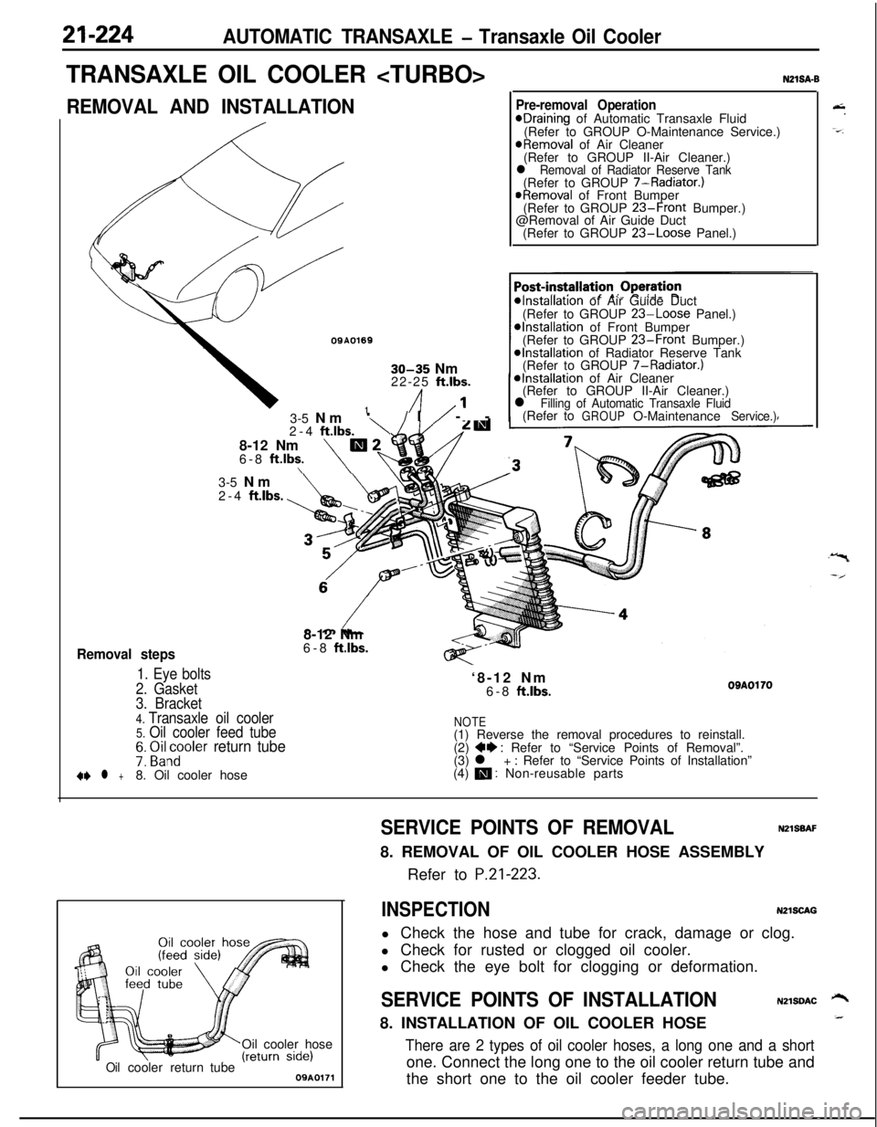
Removal steps
1. Eye bolts
2. Gasket3-5 Nm
‘\/I/ --
2-4
ftlbs.8-12 Nm
m26-8 ft.lbs.\\
N21SA-B
Pre-removal OperationeDraining of Automatic Transaxle Fluid
(Refer to GROUP O-Maintenance Service.)
@Removal of Air Cleaner
(Refer to GROUP II-Air Cleaner.)
l Removal of Radiator Reserve Tank(Refer to GROUP 7-Radiator.)
@Removal of Front Bumper
(Refer to GROUP 23-Front Bumper.)
@Removal of Air Guide Duct
(Refer to GROUP
23-Loose Panel.)
*Installation of Air Guide Duct
(Refer to GROUP 23-Loose Panel.)*Installation of Front Bumper
(Refer to GROUP 23-Front Bumper.)@Installation of Radiator Reserve Tank
(Refer to GROUP 7-Radiator.)
*Installation of Air Cleaner
(Refer to GROUP II-Air Cleaner.)
l Filling of Automatic Transaxle Fluid(Refer toGROUPO-MaintenanceService.)3-5 Nm
2-4
ftlbs.8-12 Nm
6-8
ft.lbs.‘8-12 Nm
6-8
ftlbs.OBAOl703. Bracket
4. Transaxle oil cooler5. Oil cooler feed tubeNOTE(1) Reverse the removal procedures to reinstall.
7: ~i&~oler return tube(2) ++ : Refer to “Service Points of Removal”.
(3) l + : Refer to “Service Points of Installation”
+e l +8. Oil cooler hose(4) m : Non-reusable parts
Oil cooler hose
Oilcoolerreturn tube09A0171
&.
-=-.
SERVICE POINTS OF REMOVALNZlSBAF8. REMOVAL OF OIL COOLER HOSE ASSEMBLY
Refer to
P.21-223.
INSPECTIONN2lSCAGl Check the hose and tube for crack, damage or clog.
l Check for rusted or clogged oil cooler.
l Check the eye bolt for clogging or deformation.
SERVICE POINTS OF INSTALLATIONN2lSDAC ‘-+8. INSTALLATION OF OIL COOLER HOSE_
There are 2 types of oil cooler hoses, a long one and a shortone. Connect the long one to the oil cooler return tube and
the short one to the oil cooler feeder tube.
Page 924 of 1216

-2.rt-2-30~~ AUTOMATIC TRANSAXLE - Transaxle Assembly
;haft1770083
DISASSEMBLYNZlLEAl1. Clean away any sand, mud, etc. adhered around the
.+
transaxle..
2.
Place the transaxle assembly on the workbench with the oil--’
pan down.
3. Remove the torque converter.
4. Measuring input shaft end play before disassembly will
usually indicate when a thrust washer change is required
(except when major parts are replaced). Thrust washers arelocated between reaction shaft support and rear clutch
retainer, and between reaction shaft support and front
clutch retainer.
Mount a dial indicator to converter housing with the Dial
Indicator Support. Make sure that the indicator plunger is
seated against end of input shaft.
When checking end play, pull out or push in the input shaft
with pliers. Be careful not to scratch the input shaft. Record
indicator reading for reference when reassembling transax-
le.5. Remove the pulse generator “A” and “B”
6. Remove manual control lever, then remove inhibitor
switch.
7. Remove snap ring then remove
kickdown servo switch.
Page 948 of 1216

AUTOMATIC TRANSAXLE - Transaxle Assemblv
Solder
220004858. Install new O-ring in groove of oil pump housing and apply
automatic transmission fluid lightly to outside surface of
O-ring.e59. Install oil pump assembly by tightening six bolts evenly.
i-When installing this oil pump assembly, be careful that
thrust washer will not drop.
60. Check input shaft end play. Readjust if necessary (see step
53).Standard value
: 0.3-1.0 mm (.012-,040 in.)
61, Apply solder [length approx. 10 mm (40 in.) and diameter
1.6 mm (.06 in.) to the differential assembly at the locationsshown in the illustration.
“I
-4--J62. Install the converter housing without gasket.
Caution
Don’t reuse the rubber coated metal gasket which has
been used once.
63. Tighten bolts to specification.
64. Loosen the bolts and remove the converter housing in
order to remove the pieces of solder. If the solder is not
broken, carry out the work in steps (61) to (64) with large
diameter solder.
65. Using a micrometer, measure the thickness of the flattned
solder.Select the spacer in the following manner according to
measurement.Add the thickness
[0.38 mm (015 in.)] of the rubber coated
metal gasket and the end play
LO-O.1 5 mm (O-.006 in.)] ofi4the differential case to the measurement
(T). Select a -spacer which is in the calculated range, In other words,
select a spacer whose thickness is in the range of n+ 0.38mm
(.015 in.)] to [T+ 0.38 mm (.015 in.) - 0.15 mm (.006
in.)].
Page 992 of 1216

21-298 AUTOMATIC TRANSAXLE - Transaxle Assembly 91. Insert the center shaft and hit it with a plastic hammer or
similar instrument to install it securely
.
NOTEApply ATF to the oil seal lip and do not scratch it.
92. Apply ATF to the oil pump drive hub, install the torque
converter and push it in securely so dimension A shown in
the figure reaches the standard value.
Standard value: Approximately 16.3 mm
(.642 in.)
CAUTIONS DURING COMPONENT DISASSEM-
BLY AND REASSEMBLYGeneral cautions when cleaning
1. Clean each part, blow out oil passages and oil holes, etc.
with air and check that nothing is clogged.
2. For cleaning fluid, use the designated ATF (automatic
transmission fluid) or kerosene.3. When drying parts with air, be careful not to get ATF or
kerosene on your face.Cautions when handling parts
1. After washing the parts, arrange them in order so inspec-
tion, repairs and assembly can be performed properly.
2. When disassembling the valve body, store each valve,
making a group of the various springs.
3.Soak the new brake and clutch discs used for replacementin ATF for more than 2 hours before assembly.
General cautions during reassembly
1.Be sure to apply ATF to seal rings, clutch disc, clutch plateand rotating parts and sliding parts and then install.
2.Replace all gaskets and O-ring with new ones and do not
reuse the old ones.
3.Use petrolatum to hold the parts in their specified places.
Page 1002 of 1216

21-308 AUTOMATIC TRANSAXLE - Rear Clutch Assembly
@
/
(
TFAO240SERVICE POINTS OF
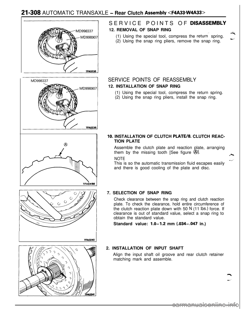
DISASSEM.BLY12. REMOVAL OF SNAP RING
(1) Using the special tool, compress the
returns spring.
(2) Using the snap ring pliers, remove the snap ring.
SERVICE POINTS OF REASSEMBLY12. INSTALLATION OF SNAP RING
(1) Using the special tool, compress the return spring.
(2) Using the snap ring pliers, install the snap ring.
10. INSTALLATION OF CLUTCH PLATE/*. CLUTCH REAC-
TION PLATE
Assemble the clutch plate and reaction plate, arranging
them by the missing tooth [See figure
@I.
NOTEThis is so the automatic transmission fluid escapes easily
and there is good cooling of the plate and disc.
7. SELECTION OF SNAP RING
Check clearance between the snap ring and clutch reaction
plate. To check the clearance, hold entire circumference ofthe clutch reaction plate down with 50
N (11 Ibs.) force. If
clearance is out of standard value, select a snap ring to
obtain the standard value.
Standard value:
1.0-1.2 mm (.034-.047 in.)
2. INSTALLATION OF INPUT SHAFT
Align the input shaft oil groove and rear clutch retainer
matching mark and assemble.
Page 1003 of 1216
.-
AUTOMATIC TRANSAXLE - End Clutch Assembly21-309END CLUTCH ASSEMBLY
NZIIJWD
F4A2233
DISASSEMBLY AND REASSEMBLYNo. of clutch discs and plates
Disassembly steps
1.Seal ring
l * 2. Snap ring3. Clutch reaction plate
4.Clutch disc5.Clutch platel + 6. Snap ring7.Washer8.Return spring9. End clutch piston
10.Oil seal11.D-ring12. End clutch retainer13.Oil seal
9
TFA0607
5TFA0608
NOTE(1) Reverse the disassembly procedures to reassemble.(2) l e : Refer to “Service Points of Disassembly”.(3) ++ : Refer to “Service Points of Reassembly”.(4) q : Non-reusable parts
SERVICE POINTS OF REASSEMBLY6. INSTALLATION OF SNAP RING
Using the special tool, install the snap ring.
Caution
Check that the snap ring is seated firmly in the groove.