Page 382 of 1216

9-98ENGINE <2.0L DOHC Engine> - Timing Belt22. REMOVAL OF TIMING BELT
Make a mark on the back of the timing belt indicating the
direction of rotation so it may be reassembled in the same
~direction if it is to be reused.
Caution
Water or oil on the belt shorten its life drastically, so
the removed timing belt, sprocket, and tensioner must
be free from oil and water. These parts should not be
washed. Replace parts if seriously contaminated.
If there is oil or water on each part check the front caseoil seals, camshaft oil seal and water pump for leaks.
26. REMOVAL OF CAMSHAFT SPROCKETS
(1) Using a wrench, hold the camshaft at its hexagon
(between the No.2 and No.3 journals) and remove the
camshaft sprocket bolt.
Caution
Locking the camshaft sprocket with a tool damagesthe sprocket.
(2) Remove the camshaft sprockets.
127. REMOVAL OF OIL PUMP SPROCKET
(1) Remove the plug on the side of the cylinder block.
(2) Insert a Phillips screwdriver [shank diameter 8 mm
(.31in.)] to block the left silent shaft.
(3) Remove the oil pump sprocket nut.
(4) Remove the oil pump sprocket.
33. REMOVAL OF TIMING BELT “B”
Make a mark on the back of the timing belt indicating the
direction of rotation so it may be reassembled in the same
direction if it is to be reused.
Caution
Water or oil on the belt shorten its life drastically, so
++the removed timing belt, sprocket, and tensioner must
be free from oil and water. These parts should not be
washed. Replace parts if seriously contaminated.
If there is oil or water on each part check the front caseoil seals, camshaft oil seal and water pump for leaks.
Page 388 of 1216

ENGINE <2.0L DOHC Engine> - Timing BeltDowelCamshaft sprocket
Timing mark
6EN0264
Tim
mar22. INSTALLATION OF TIMING BELT
(1) Turn the two sprockets so that their dowel
pind arti
located on top. Then, align the timing marks facing each
-
*other with the top surface of the cylinder head. When,
you let go of the exhaust camshaft sprocket, it will
rotate one tooth in the counterclockwise direction. This
should be taken into account when installing the timing
belt on the sprockets.
NOTE
The same camshaft sprocket is used for the intake andexhaust camshafts and is provided with two timing
marks. When the sprocket is mounted on the exhaust
camshaft, use the timing mark on the right with the
*dowel pin hole on top. For the intake camshaft
-sprocket, use the one on the left with the dowel pin
hole on top.
(2) Align the crankshaft sprocket timing mark.
(3) Align the oil pump sprocket timing mark.
(4) Remove the plug on the cylinder block and insert a
Phillips screwdriver [shank diameter 8 mm
(.31 in.)]
through the hole.
If it can be inserted as deep as 60 mm (2.4 in.) or more,the timing marks are correctly aligned. If the inserted
depth is only
20-25 mm (.8-l .O in.), turn the oil pump
sprocket one turn and realign timing marks. Then checkto ensure that the screwdriver can be inserted 60 mm
(2.4 in.) or more. Keep the screwdriver inserted until theinstallation of the timing belt is finished.,+
.
NOTEStep (4) is performed to ensure that the oil pump
sprocket is correctly positioned with reference to the
silent shafts.
Page 389 of 1216
ENGINE <2.0L DOHC Engine> - Timing Belt9405
I
P(5) Thread the timing belt over the intake side camshaft
sprocket and fix it an indicated position by a clip.
(6) Thread the timing belt over the exhaust side sprocket,
aligning the timing marks with the cylinder head top
surface using two wrenches.
(7) Fix the belt at indicated position by a clip.
(8) Thread the timing belt over the idler pulley, the oil pumpsprocket, the crankshaft sprocket and the tension
pulley in the order shown.
(9) Remove the two clips.
(1O)Lift up the tensioner pulley in the direction of arrow andtighten the center bolt.
(11)Check to see that all timing marks are lined up.
(12)Remove the screwdriver inserted in step (4) and fit the
plug.
(13)Give the crankshaft a quarter counterclockwise turn.
Then, turn it clockwise until the timing marks are lined
up again.
Page 394 of 1216

9-110ENGINE <2.0L DOHC Engine> - Camshaft and Rocker Arm
I
I6EN0183
I6EN0184
I
I6EN0185
,I
+Front of engine (Timing belt side)
WIB’ S’it
’ Intake side
camshaft
6E NO289Cap number
Symbolidentifying
intake or
exhaust6EN6464
I
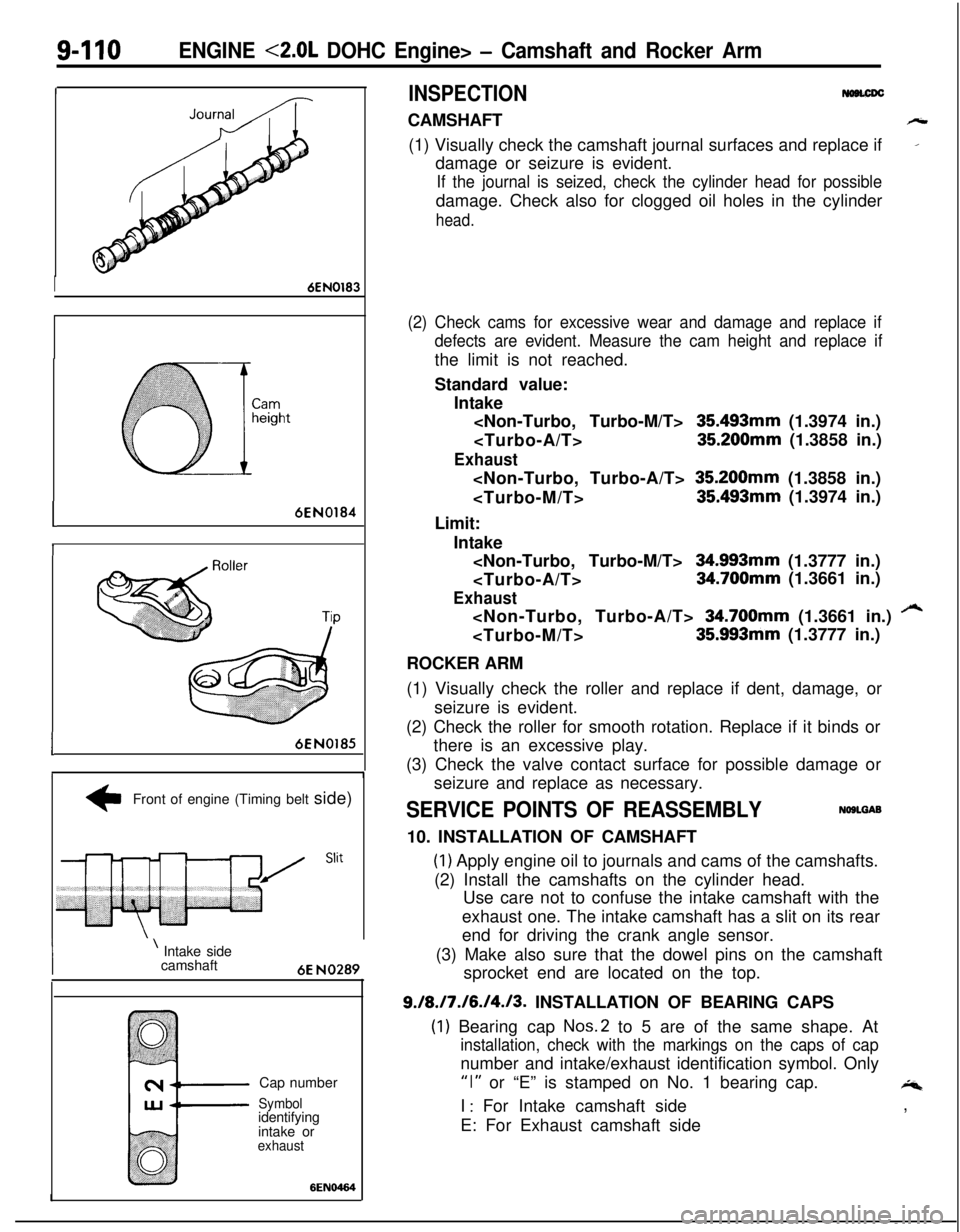
INSPECTIONCAMSHAFT
h(1) Visually check the camshaft journal surfaces and replace if
_damage or seizure is evident.
If the journal is seized, check the cylinder head for possibledamage. Check also for clogged oil holes in the cylinder
head.
(2) Check cams for excessive wear and damage and replace if
defects are evident. Measure the cam height and replace ifthe limit is not reached.
Standard value:
Intake
35493mm (1.3974 in.)
35.200mm (1.3858 in.)
Exhaust 35.200mm (1.3858 in.)
35.493mm (1.3974 in.)
Limit:
Intake
34.993mm (1.3777 in.)
34.700mm (1.3661 in.)
Exhaust 34.700mm (1.3661 in.)
/“435.993mm (1.3777 in.)
ROCKER ARM
(1) Visually check the roller and replace if dent, damage, or
seizure is evident.
(2) Check the roller for smooth rotation. Replace if it binds or
there is an excessive play.
(3) Check the valve contact surface for possible damage or
seizure and replace as necessary.
SERVICE POINTS OF REASSEMBLYNOSLGAB10. INSTALLATION OF CAMSHAFT
(1) Apply engine oil to journals and cams of the camshafts.
(2) Install the camshafts on the cylinder head.
Use care not to confuse the intake camshaft with the
exhaust one. The intake camshaft has a slit on its rear
end for driving the crank angle sensor.
(3) Make also sure that the dowel pins on the camshaft
sprocket end are located on the top.
9./8./7./6./4./3. INSTALLATION OF BEARING CAPS
(1) Bearing cap Nos.2 to 5 are of the same shape. At
installation, check with the markings on the caps of capnumber and intake/exhaust identification symbol. Only
“I” or “E” is stamped on No. 1 bearing cap.4I
: For Intake camshaft side
E: For Exhaust camshaft side,
Page 395 of 1216

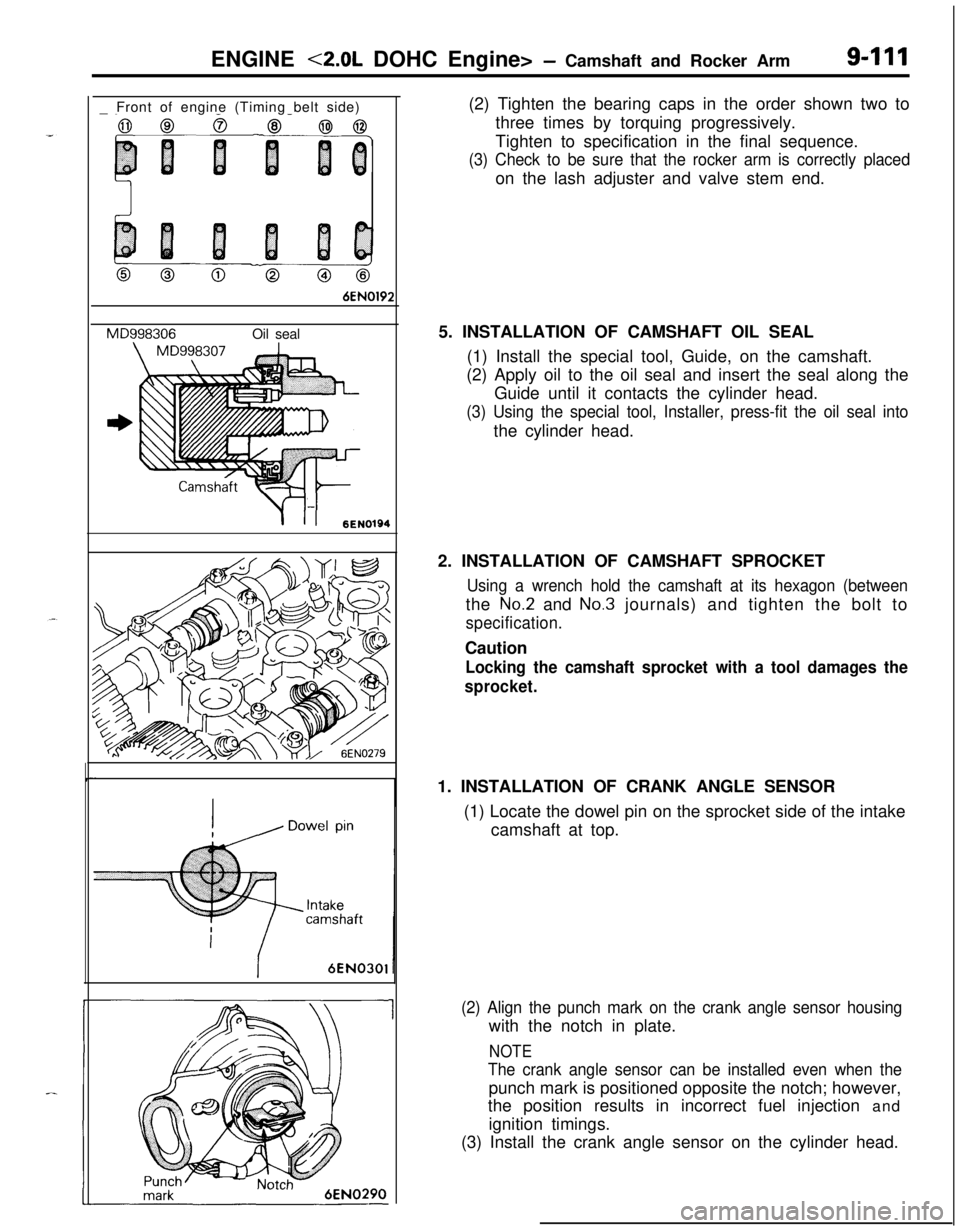
ENGINE <2.0L DOHC Engine> - Camshaft and Rocker Arm9-111_ Front of engine (Timing belt side)
0 Co@
6EN0192
MD998306Oil seal
-
Y-II6ENI01946EN030’
1(2) Tighten the bearing caps in the order shown two to
three times by torquing progressively.
Tighten to specification in the final sequence.
(3) Check to be sure that the rocker arm is correctly placedon the lash adjuster and valve stem end.
5. INSTALLATION OF CAMSHAFT OIL SEAL
(1) Install the special tool, Guide, on the camshaft.
(2) Apply oil to the oil seal and insert the seal along the
Guide until it contacts the cylinder head.
(3) Using the special tool, Installer, press-fit the oil seal intothe cylinder head.
2. INSTALLATION OF CAMSHAFT SPROCKET
Using a wrench hold the camshaft at its hexagon (betweenthe
No.2 and No.3 journals) and tighten the bolt to
specification.Caution
Locking the camshaft sprocket with a tool damages the
sprocket.1. INSTALLATION OF CRANK ANGLE SENSOR
(1) Locate the dowel pin on the sprocket side of the intake
camshaft at top.
(2) Align the punch mark on the crank angle sensor housingwith the notch in plate.
NOTE
The crank angle sensor can be installed even when thepunch mark is positioned opposite the notch; however,
the position results in incorrect fuel injection and
ignition timings.
(3) Install the crank angle sensor on the cylinder head.
Page 397 of 1216

ENGINE <2.0L DOHC Engine> - Cylinder Head and Valve9-l 13
.
.
a Front of engine (Timing belt side)
6EN0211
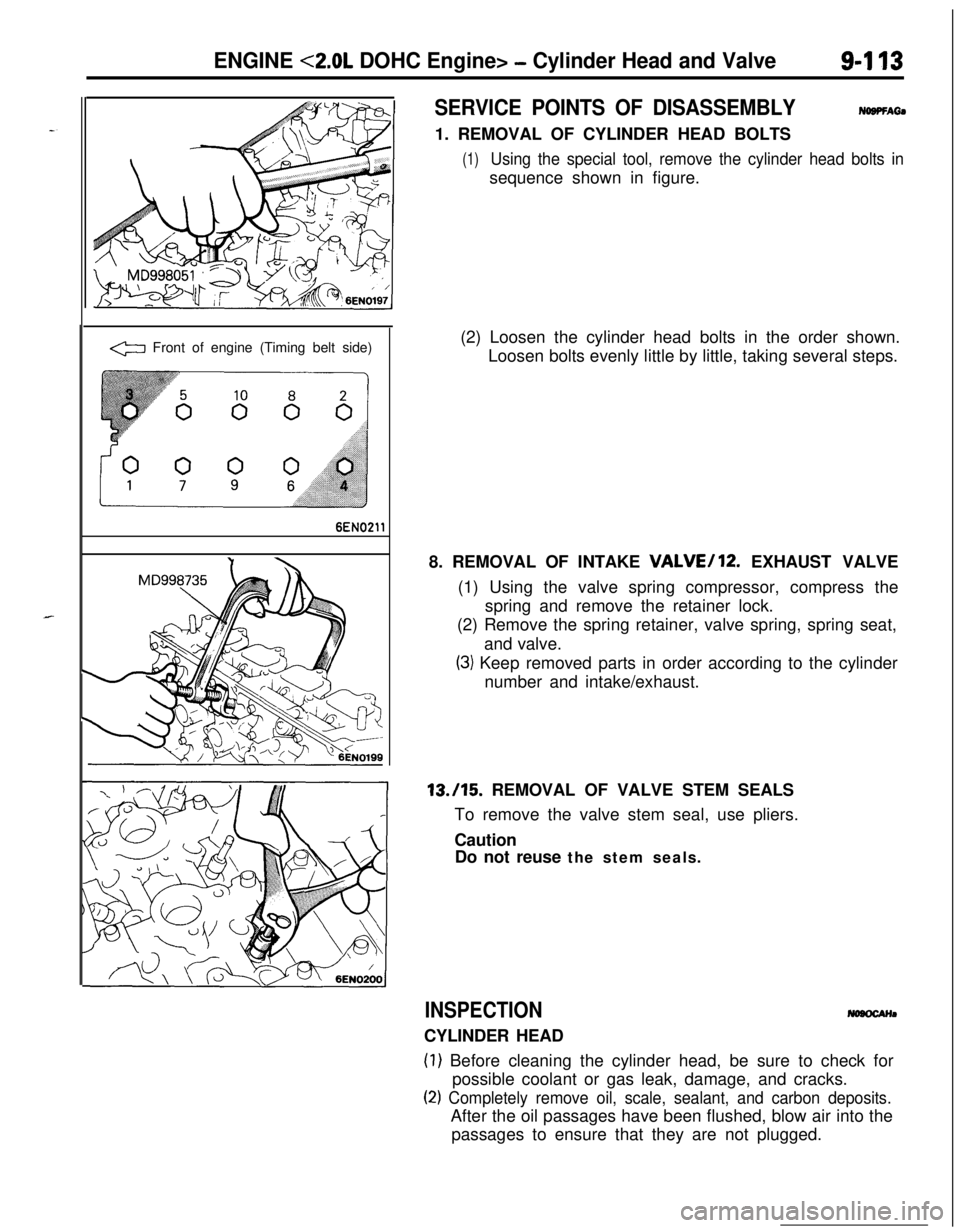
SERVICE POINTS OF DISASSEMBLYNOBPFAti1. REMOVAL OF CYLINDER HEAD BOLTS
(1)Using the special tool, remove the cylinder head bolts insequence shown in figure.
(2) Loosen the cylinder head bolts in the order shown.
Loosen bolts evenly little by little, taking several steps.
8. REMOVAL OF INTAKE
VALVE/12. EXHAUST VALVE
(1) Using the valve spring compressor, compress the
spring and remove the retainer lock.
(2) Remove the spring retainer, valve spring, spring seat,
and valve.
(3) Keep removed parts in order according to the cylinder
number and intake/exhaust.13./15. REMOVAL OF VALVE STEM SEALS
To remove the valve stem seal, use pliers.
Caution
Do not reuse the stem seals.
INSPECTIONCYLINDER HEAD
(1) Before cleaning the cylinder head, be sure to check for
possible coolant or gas leak, damage, and cracks.
(2) Completely remove oil, scale, sealant, and carbon deposits.After the oil passages have been flushed, blow air into the
passages to ensure that they are not plugged.
Page 401 of 1216

ENGINE <2.0L DOHC Engine> -Front Case, Oil Pump and Silent Shaft9-117
FRONT CASE, OIL PUMP AND SILENT SHAFT
DISASSEMBLY AND REASSEMBLY
40-45 Nm29-33 ft.lbs.
\
32
I
NOSRF-B11-13
ft.lbs.
LO8-12 Nm6-9 ft.lbs.\
\715-22 Nm -11-16 ft.lbs.,15-22
Nm11-16 ft.lbs.
Disassembly steps
I. Drain pluo
\/‘16EN046835-45
Nm25-33 ft.lbs.2.Gasket-l + 3. Oil filter
4. Oil cooler bolt (Turbo)
~~ 5. Oil cooler (Turbo)
6. Oil pressure switch
7.Harness assembly8. Oil pressure gauge unit
9.Oil pan10.Oil screen
11.Gasket12. Oil filter bracket
13.Gasket14.Relief plug
15.Gasket16.Relief spring17.Relief plunger
l 4 23. Oil seall + 24. Silent shaft oil seall + 25. Crankshaft front oil seal26. Oil pump cover
l * 27. Oil pump driven geare+ 28. Oil pump drive gear
29. Left silent shaft
30. Right silent shaft
W W 31. Silent shaft front bearings
W W 32. Right silent shaft rear bearing
~~ ~~ 33. Left silent shaft rear bearing34. Check valve (Turbo)
35. Gasket (Turbo)
l + 36. Oil jet (Turbo)37. Gasket (Turbo)
l I) W 18. Plug cap-NOTE19. O-ring(1) Reverse the disassembly procedures to reassemble.+e I)+ 20. Driven gear bolt(2) 4I) : Refer to “Service Points of Disassembly”.
I)+ 21. Front case(3) ~~ : Refer to “Service Points of Reassembly”.
22. Gasket(4) m : Non-reusable parts
Page 403 of 1216

ENGINE <2.0L DOHC Engine>- Front Case, Oil Puma and Silent Shaft9419
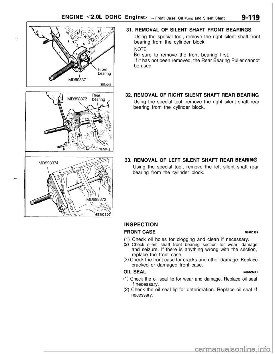
3EN04131. REMOVAL OF SILENT SHAFT FRONT BEARINGS
Using the special tool, remove the right silent shaft front
bearing from the cylinder block.
NOTE
Be sure to remove the front bearing first.
If it has not been removed, the Rear Bearing Puller cannot
be used.
32. REMOVAL OF RIGHT SILENT SHAFT REAR BEARING
Using the special tool, remove the right silent shaft rear
bearing from the cylinder block.
33. REMOVAL OF LEFT SILENT SHAFT REAR
BEARINGUsing the special tool, remove the left silent shaft rear
bearing from the cylinder block.
INSPECTION
FRONT CASE
NOSRCJCl(1) Check oil holes for clogging and clean if necessary.
(2) Check silent shaft front bearing section for wear, damage
and seizure. If there is anything wrong with the section,
replace the front case.
(3) Check the front case for cracks and other damage. Repladecracked or damaged front case.
OIL SEAL
NOSRCMAl
(1) Check the oil seal lip for wear and damage. Replace oil sealif necessary.
(2) Check the oil seal lip for deterioration. Replace oil seal
!if
necessary.