Page 355 of 1216

ENGINE - Crankshaft, Flwvheel and Drive Plate9-71
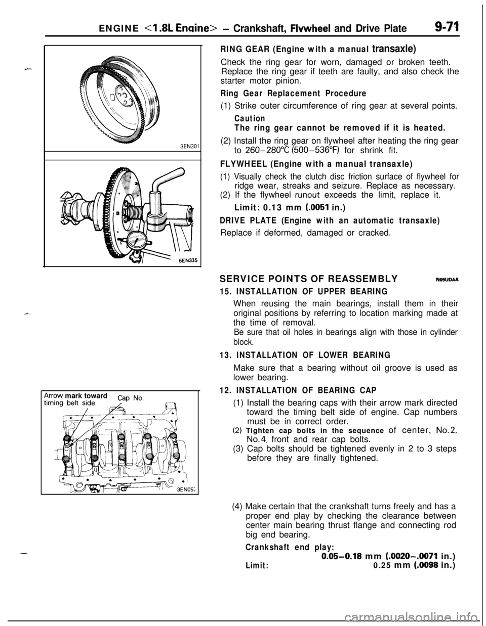
3EN30’lrrow mark toward
cap No,
I
RING GEAR (Engine with a manual transaxle)Check the ring gear for worn, damaged or broken teeth.
Replace the ring gear if teeth are faulty, and also check the
starter motor pinion.
Ring Gear Replacement Procedure(1) Strike outer circumference of ring gear at several points.
Caution
The ring gear cannot be removed if it is heated.(2) Install the ring gear on flywheel after heating the ring gear
to
260-280°C (500-536°F) for shrink fit.
FLYWHEEL (Engine with a manual transaxle)
(1) Visually check the clutch disc friction surface of flywheel forridge wear, streaks and seizure. Replace as necessary.
(2) If the flywheel
runout exceeds the limit, replace it.
Limit: 0.13 mm (0051 in.)
DRIVE PLATE (Engine with an automatic transaxle)Replace if deformed, damaged or cracked.
SERVICE POINTS OF REASSEMBLY
NOSUDAA
15. INSTALLATION OF UPPER BEARINGWhen reusing the main bearings, install them in their
original positions by referring to location marking made at
the time of removal.
Be sure that oil holes in bearings align with those in cylinder
block.
13. INSTALLATION OF LOWER BEARINGMake sure that a bearing without oil groove is used as
lower bearing.
12. INSTALLATION OF BEARING CAP(1) Install the bearing caps with their arrow mark directed
toward the timing belt side of engine. Cap numbers
must be in correct order.(2) Tighten cap bolts in the sequence of center,
No.2,
No.4. front and rear cap bolts.
(3) Cap bolts should be tightened evenly in 2 to 3 steps
before they are finally tightened.
(4) Make certain that the crankshaft turns freely and has a
proper end play by checking the clearance between
center main bearing thrust flange and connecting rod
big end bearing.
Crankshaft end play:
0.05-0.18 mm (.0020-.0071 in.)
Limit:0.25 mm (.0098 in.)
Page 356 of 1216

9-72ENGINE <1.8L Engine> -Crankshaft, Flywheel and Drive Plate/Cylinder Block
PressOil seal
I
MD99801 1
/
Oil seal case1 EN06L
CYLINDER BLOCK
i//
199.
INSTALLATlON OF REAR OIL SEAL
Install oil seal in the crankshaft rear oil seal case. Using the
special tool, press fit the oil seal all the way in without tiltingiii
it.DISASSEMBLY AND REASSEMBLY
FORWARD
50-70 Nm37-50 ft.lbs.
30-42 Nm22-30 ft.lbs.
NDBVF-A
110-130 Nm80-94 ft.lbs.1. Exhaust pipe support bracket
2. Front roll stopper bracket
3. Rear roll stopper bracket
4. Left engine support bracket5. Cylinder block6. Engine mount bracket
3EN0092
INSPECTIONl Visually check the cylinder block for scores, rust and
corrosion. Also check for cracks or any other faults by using
the magnaflux method. Correct or replace the block if
faulty.
lMeasure the cylinder bore with a cylinder gauge at three
levels and in two directions A and
B as shown. If
out-of-round or taper is more than specified or if the
cylinder walls are badly scuffed or scored, the cylinder
&block should be rebored and honed, and new oversize
_pistons and rings fitted.
Measuring points are as shown.
Cylinder bore: 80.8 mm (3.173 in.)
Out-of-round and taper: 0.01 mm (.0004 in.)
Page 358 of 1216

9-74ENGINE <2.0L DOHC Engine>- Service Adjustment Procedures
ENGINE <2.0L DOHC Engine>
SERVICE ADJUSTMENT PROCEDURES pi
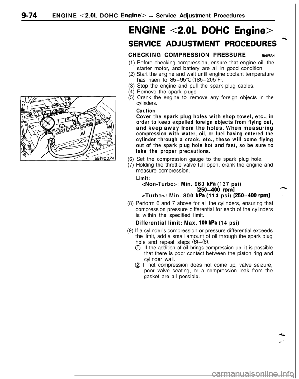
CHECKING COMPRESSION PRESSURENOSFFAH(1) Before checking compression, ensure that engine oil, the
starter motor, and battery are all in good condition.
(2) Start the engine and wait until engine coolant temperature
has risen to
85-95°C (185-205°F).
(3) Stop the engine and pull the spark plug cables.
(4) Remove the spark plugs.
(5) Crank the engine
to. remove any foreign objects in the
cylinders.
Caution
Cover the spark plug holes with shop towel, etc., in
order to keep expelled foreign objects from flying out,and keep away from the holes. When measuring
compression with water, oil, or fuel having entered the
cylinder through a crack, etc., these will come flying
out of the spark plug hole hot and fast, so be sure to
take the proper precautions.(6) Set the compression gauge to the spark plug hole.
(7) Holding the throttle valve full open, crank the engine and
measure compression.
Limit:
: Min. 960 kPa (137 psi)
[250-400 rpm]6: Min. 800
kPa (114 psi) [250-400 rpml-(8) Perform 6 and 7 above for all the cylinders, ensuring that
compression pressure differential for each of the cylinders
is within the specified limit.
Differential limit: Max. 100 kPa (14 psi)(9) If a cylinder’s compression or pressure differential exceeds
the limit, add a small amount of oil through the spark plug
hole and repeat steps (6)-(8).
@If the addition of oil brings compression up, it is possiblethat there is poor contact between the piston ring and
cylinder wall.
@ If not compression does not come up, valve seizure,
poor valve seating, or a compression leak from the
gasket are all possible.‘I
Page 360 of 1216

9-76ENGINE <2.0L DOHC Engine> -Service Adjustment Procedures
LASH ADJUSTERS CHECKNOBFEABalIf an abnormal noise is heard from the lash adjusters check as
follows.
(1) After warming up the engine, stop it.
(2) While installed to the cylinder head, press the part of rockerarm that contacts the lash adjuster. The part pressed will
feel very hard if the lash adjuster condition is normal.
(3) If, when pressed, it easily descends all the way downward,
replace the lash adjuster.
(4) If there is a spongy feeling when pressed, air is probably
mixed in, and so the cause should be investigated. The
cause is probably an insufficient amount of engine oil, or
damage to the oil screen and/or screen gasket.
(5) After finding the cause and taking the appropriate step
(adding oil or repair), warm up the engine and drive at low
speed for a short time. Then, after stopping the engine andwaiting a few minutes, drive again at low speed. Repeat
this procedure a few times to bleed out the air from the oil.
Page 367 of 1216

r-.ENGINE <2.0L DOHC Engine>
- Engine AssemblyS-83
OlA0177
-mpp.-/- --OlA0553
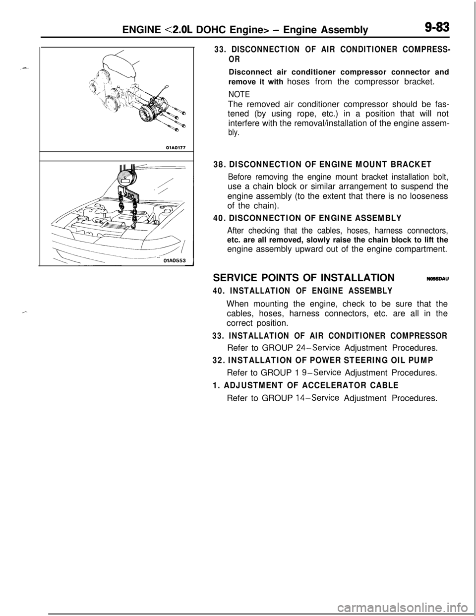
33. DISCONNECTION OF AIR CONDITIONER COMPRESS-
ORDisconnect air conditioner compressor connector and
remove it with hoses from the compressor bracket.
NOTEThe removed air conditioner compressor should be fas-
tened (by using rope, etc.) in a position that will not
interfere with the removal/installation of the engine assem-
bly.
38. DISCONNECTION OF ENGINE MOUNT BRACKET
Before removing the engine mount bracket installation bolt,use a chain block or similar arrangement to suspend the
engine assembly (to the extent that there is no looseness
of the chain).
40. DISCONNECTION OF ENGINE ASSEMBLY
After checking that the cables, hoses, harness connectors,etc. are all removed, slowly raise the chain block to lift the
engine assembly upward out of the engine compartment.
SERVICE POINTS OF INSTALLATION
NOSSDAU
40. INSTALLATION OF ENGINE ASSEMBLYWhen mounting the engine, check to be sure that the
cables, hoses, harness connectors, etc. are all in the
correct position.
33. INSTALLATION OF AIR CONDITIONER COMPRESSORRefer to GROUP
24-Service Adjustment Procedures.
32. INSTALLATION OF POWER STEERING OIL PUMPRefer to GROUP 1
g-service Adjustment Procedures.
1. ADJUSTMENT OF ACCELERATOR CABLERefer to GROUP 14-Service Adjustment Procedures.
Page 369 of 1216

ENGINE <2.0L DOHC Engine> -Camshafts and Camshaft Oil Seals9-85Plastic hammer
Intake side
Exhaust side
Jzzl
(22
Slits
11. REMOVAL OF EXHAUST CAMSHAFT SPROCKET/
12. INTAKE CAMSHAFT SPROCKET(1) Using a wrench at the hexagonal part of the camshaft
(to prevent the crankshaft from turning), loosen the
cramshaft sprocket bolt.
(2) Remove the camshaft sprokets.
13. REMOVAL OF CAMSHAFT OIL SEALSRemove the oil seals using a screwdriver or similar tool.
Caution
Take care not to damage front camshaft bearing cap
and camshaft.
14./15./16./17. REMOVAL OF CAMSHAFT BEARfNG CAPS(1) Loosen the bearing cap installation bolts in two or
three steps.
(2) Remove the bearing cap.
NOTEIf the bearing cap is difficult to remove, use a plastic
hammer to gently tap the rear
.part of the camshaft,
and then remove.
SERVICE POINTS OF INSTALLATIONNO92DAB
lg. INSTALLATION OF INTAKE CAMSHAFT/18. EXHAUST
CAMSHAFT(1) Install the camshafts on the cylinder head.
Caution
Be sure not to mistake the intake side and the
exhaust side. There are slits for crank angle sensor
drive in the rear end of the intake camshaft.
NOTEInstall new camshafts using the following procedure.
(1) Remove the rocker arms.
(2) Lay the camshafts on the cylinder head and install
the bearing caps.
(3) Check that the camshaft can be easily turned by
hand.(4) After checking, remove the bearing caps and the
camshafts, and install the rocker arms.
Page 370 of 1216

9-86ENGINE <2.0L DOHC Engine> -Camshafts and Camshaft Oil Seals
rMD998306qil seal
coatithe
mrenceof the guide.
6EN612Matingmark atMating mark at
llA0361Semi-circular packing
Awlv sealant(2) The camshaft’s dowel pins should be at the positions
shown in the figure.
17./16./15./14. INSTALLATION OF CAMSHAFT BEARING
CAPSTighten the bearing cap installation bolts to the specified
torque in two or three steps.
Caution
Tighten uniformly, otherwise the rocker arms will not
be straight.
13. INSTALLATION OF CAMSHAFT OIL SEALSUsing the special tool, press in the oil seal as shown in the
figure.
_-‘7
10. INSTALLATION OF THE CRANKSHAFT ANGLE SENSOR(1) Align the mating mark (punch mark) on the housing of
the crank angle sensor with the mating mark (notch) in
the plate.
(2) Install the crank angle sensor to the engine.
Caution
When tightening the nut of the crankshaft angle
sensor, make sure that the crank angle sensor does
not turn.(3) Check that the ignition timing is set at the standard
value. (Refer to GROUP
8-Ignition System.)
8. INSTALLATION OF SEMI-CIRCULAR PACKINGInstall the semi-circular packing to the cylinder head, and
apply a coating of the specified sealant where shown in
the figure.
Ak
Specified sealant: MOPAR Part No.4318034
or equivalent
Page 373 of 1216
ENGINE <2.0L DOHC Engine> - Oil Pan and Oil Screen9-89
Sealant
Grooveole of bolt
0180052
INSPECTION&SHOW
lCheck the oil pan for damage and cracks. Replace if faulty.l Check the oil screen for clogging; damage and cracks.
Replace if faulty.
SERVICE POINTS OF INSTALLATION
NOSHDASa
11. INSTALLATION OF OIL PAN
(1) Use a wire brush or other tool to scrape clean all gasketsurfaces of the cylinder block and oil pan so that all
loose material is removed.
(2) Gasket surfaces must be free of oil and dirt.
(3) Apply the specified sealant around the gasket surface
of the oil pan as specified in illustration.
Specified sealant: MITSUBISHI GENUINE PART
No.
MD9971 10 or equivalent
NOTEThe sealant should be applied in a continuous head
approximately 4 mm
(.I 6 in.) in diameter.
(4) Assemble oil pan to cylinder block within 15 minutes
after applying the sealant.
CautionAfter installing the oil pan, wait at least 30 minutes
before starting the engine.