1991 MITSUBISHI ECLIPSE check oil
[x] Cancel search: check oilPage 178 of 1216
![MITSUBISHI ECLIPSE 1991 Service Manual 5-38BRAKES - Anti-lock Braking System Troubleshooting
E-5Abnormality of solenoid valve drive circuit
[Explanation]*>The ABS ECU normally monitors the solenoid valve
when turned OFF, the ECU determines MITSUBISHI ECLIPSE 1991 Service Manual 5-38BRAKES - Anti-lock Braking System Troubleshooting
E-5Abnormality of solenoid valve drive circuit
[Explanation]*>The ABS ECU normally monitors the solenoid valve
when turned OFF, the ECU determines](/manual-img/19/57104/w960_57104-177.png)
5-38BRAKES - Anti-lock Braking System Troubleshooting
E-5Abnormality of solenoid valve drive circuit
[Explanation]*>The ABS ECU normally monitors the solenoid valve
when turned OFF, the ECU determines the solenoid%’ -’drive circuit.coil wire is broken/short circuited or the harness is
If no current flows in the solenoid even if the ECUbroken/short circuited and then the warning light
turns the solenoid ON or if it continues to flow evenlights up.
IGNITIONSWITCH(IGI)
7JIB------_-_tor and check with the
side connector.
Connect HU
1OP connec-
disconnect ECU con-
>Is the solenoid valve resis-
tance value within the range
of the standard values when
measured at the ECU con-
nector?Standard value:
3.0-3.2 Q
Yes1
II
I
Solenoid valve drive circuit isnormal.I
NoReplace HU.I
NoIs the resistance value for
the solenoid valve within the
range ofthe standard
values?Standard value:
3.0-3.2 Q, IYes ,
1
JThe harness wire for the
solenoidvalvecircuit
whose resistance value is
outside the range of the
standard value is broken
or short circuited.,-‘he-
-Repair
Page 185 of 1216

BRAKES - Service Adiustment Procedures5-45I
\\14A0416
2314A04.54
BLEEDINGN65FYAN
When the master cylinder is empty of brake fluid, bleed air
from the master cylinder by proceeding with procedures (1)
thru (6). (Because this master cylinder is not equipped with a
check valve.)
When brake fluid remains in the master cylinder, proceed with
step (6).
(1) -Disconnect the brake tube from the master cylinder.
(2) Two persons should conduct the air bleeding, one person
slowly depressing the brake pedal and holding the pedal
depressed.(3) In this condition, the other person should use a finger to
close the outlet part of the master cylinder, and then the
first person should release the brake pedal.
(4) Steps (2) and (3) should be repeated three or four times,
and then the master cylinder should be filled with brake
fluid to the specified level.
NOTE
The air is completely bled from the master cylinder by steps
(1) to (4).
(5) Connect the brake tube to the master cylinder.
(6) Start the engine; then, in the sequence shown in the
illustration, bleed the air from each wheel cylinder.
Specified brake fluid: MOPAR Brake Fluid/
Conforming to DOT3
Caution
1.Use the specified brake fluid. Avoid using a mixture
of the specified brake fluid and other fluid.2. If brake fluid is exposed to the air, it will absorb
moisture; as water is absorbed from the atmos-phere, the boiling point of the brake fluid will
decrease and the braking performance will be
seriously impaired. For this reason, use a hermeti-
cally sealed 1 lit.
(1.06 qt.) or 0.5 lit. (0.52 qt.) brake
fluid container.3. Firmly close the cap of the brake fluid container
after use.
4. For vehicles with the anti-lock braking system, besure to install a filter to the master cylinder
reservoir tank when supplying brake fluid.
ORDINARY AIR-BLEEDING PROCEDURES(1) Depress the brake pedal several times until resistance is
felt; then, with the pedal depressed, loosen the bleeder
screw
l/3 to l/2 turn and then tighten it before the fluid
pressure is all gone.
(2) Release the brake pedal. Repeat this procedure until there
are no more air bubbles in the brake fluid.
Page 247 of 1216
CLUTCH - Clutch Cover and Disc647
08A0038
6CLOO3SERVICE POINTS OF REMOVAL
NO6OSAH
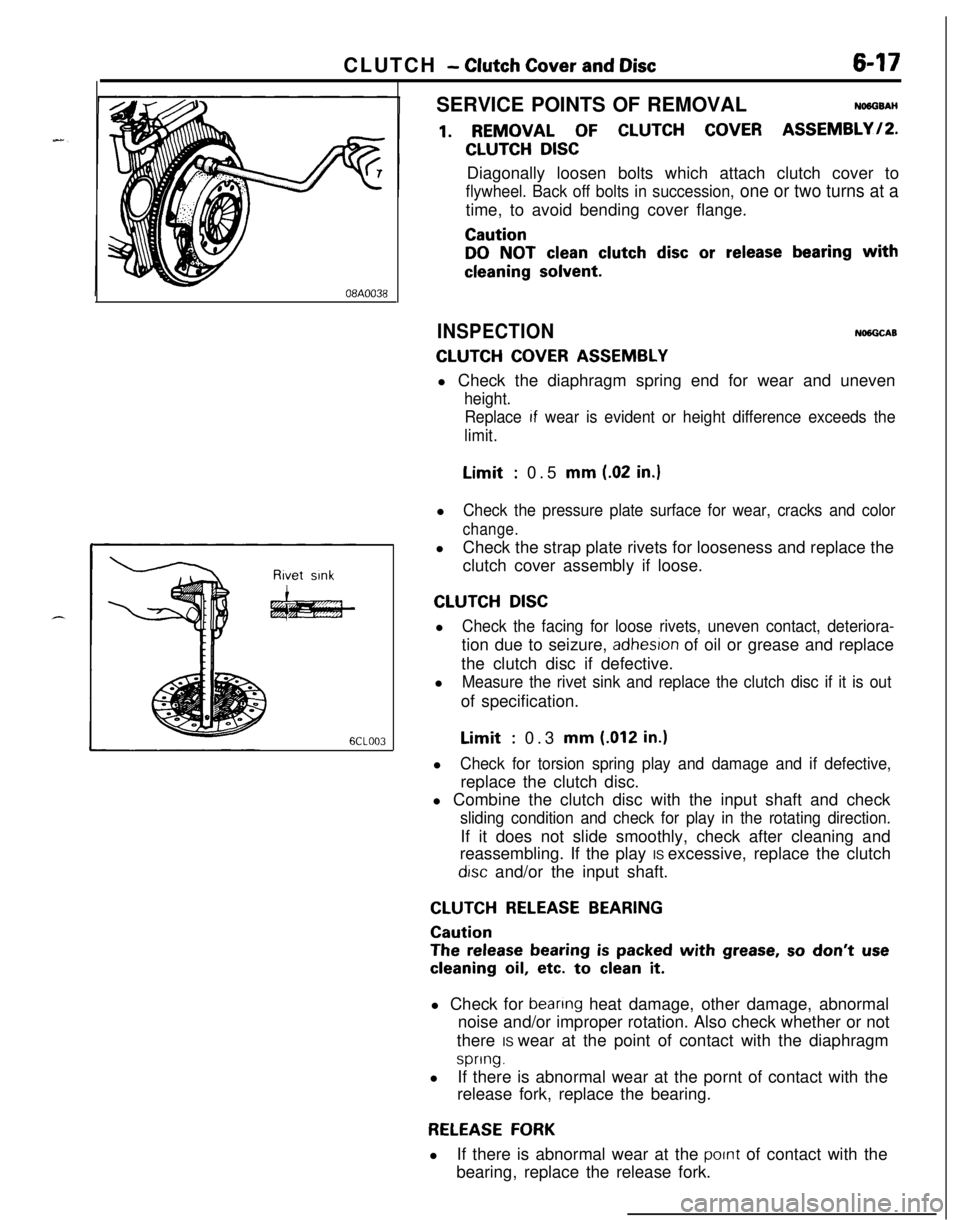
1. REMOVAL OF CLUTCH COVER ASSEMBLY/P.
CLUTCH DISCDiagonally loosen bolts which attach clutch cover to
flywheel. Back off bolts in succession, one or two turns at atime, to avoid bending cover flange.
Caution
DO NOT clean clutch disc or release bearing with
cleaning solvent.
INSPECTIONNlNGCAB
CLUTCH COVER ASSEMBLYl Check the diaphragm spring end for wear and uneven
height.
Replace
If wear is evident or height difference exceeds the
limit.Limit
: 0.5 mm (.02 in.)l
Check the pressure plate surface for wear, cracks and color
change.lCheck the strap plate rivets for looseness and replace the
clutch cover assembly if loose.
CLUTCH DISCl
Check the facing for loose rivets, uneven contact, deteriora-tion due to seizure,
adhesron of oil or grease and replace
the clutch disc if defective.
l
Measure the rivet sink and replace the clutch disc if it is outof specification.Limit
: 0.3 mm (.012 in.)l
Check for torsion spring play and damage and if defective,replace the clutch disc.
l Combine the clutch disc with the input shaft and check
sliding condition and check for play in the rotating direction.If it does not slide smoothly, check after cleaning and
reassembling. If the play IS excessive, replace the clutch
drsc and/or the input shaft.
CLUTCH RELEASE BEARING
Caution
The release bearing is packed with grease, so don’t use
cleaning oil, etc. to clean it.l Check for
beanng heat damage, other damage, abnormal
noise and/or improper rotation. Also check whether or not
there IS wear at the point of contact with the diaphragm
spring.lIf there is abnormal wear at the pornt of contact with the
release fork, replace the bearing.
RELEASE FORKlIf there is abnormal wear at the
pornt of contact with the
bearing, replace the release fork.
Page 255 of 1216
COOLING - Troubleshooting7A7
OPERATION
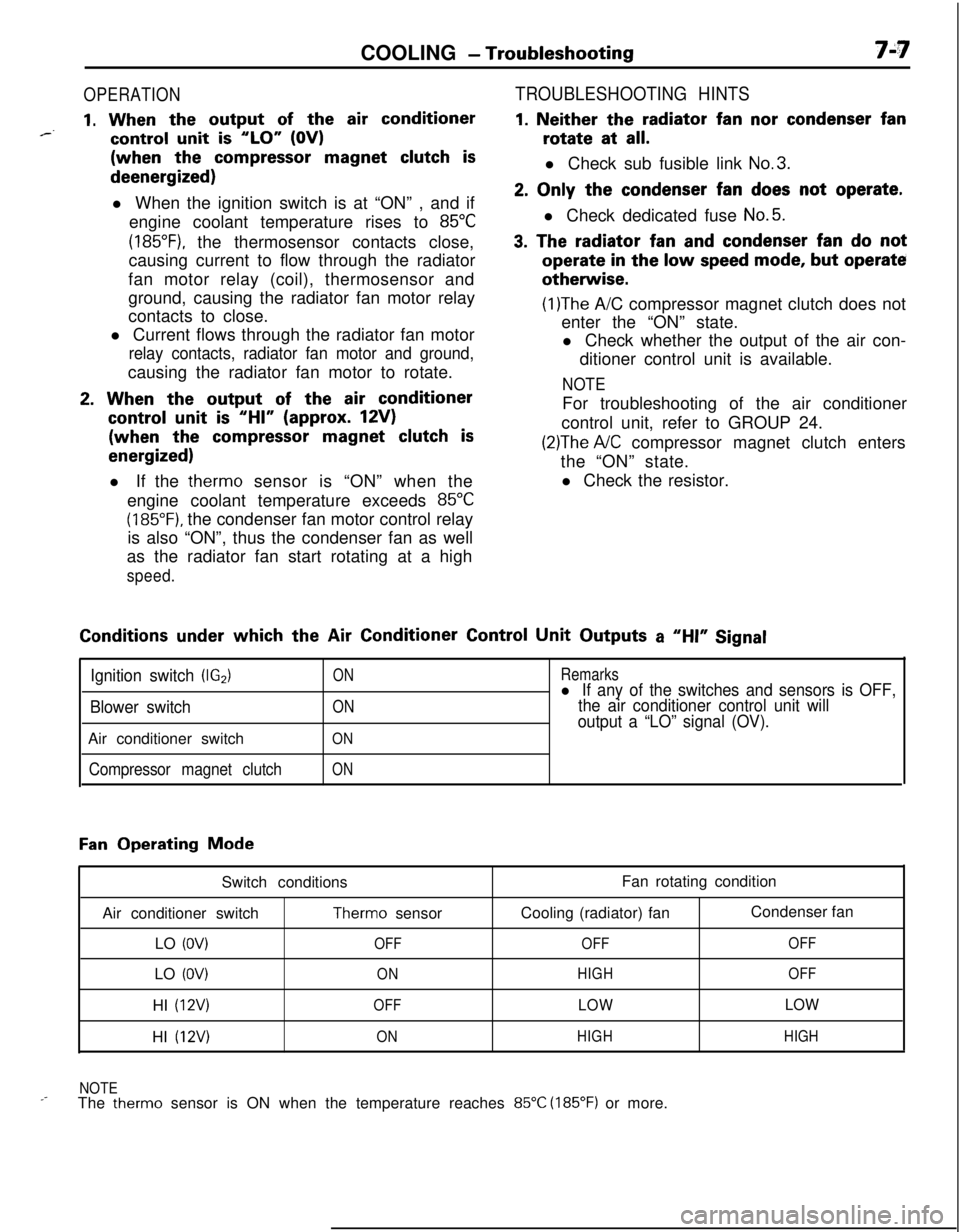
1. When the output of the air conditioner*--control unit is “LO” (OV)(when the
compressor magnet clutch isdeenergized)
l When the ignition switch is at “ON” , and if
engine coolant temperature rises to
85°C
(185”F), the thermosensor contacts close,
causing current to flow through the radiator
fan motor relay (coil), thermosensor and
ground, causing the radiator fan motor relay
contacts to close.
l Current flows through the radiator fan motor
relay contacts, radiator fan motor and ground,causing the radiator fan motor to rotate.
2. When the output of the air conditioner
control unit is “HI” (approx. 12V)(when the
compressor magnet clutch is
energized)l If the therm0 sensor is “ON” when the
engine coolant temperature exceeds
85°C
(185°F). the condenser fan motor control relay
is also “ON”, thus the condenser fan as well
as the radiator fan start rotating at a high
speed.
TROUBLESHOOTING HINTS
1. Neither the radiator fan nor condenser fanrotate at
all.l Check sub fusible link
No.3.
2. Only the condenser fan does not operate.l Check dedicated fuse
No.5.
3. The radiator fan and condenser fan do notoperate
in the low speed mode, but operateotherwise.
(1)The A/C compressor magnet clutch does not
enter the “ON” state.
l Check whether the output of the air con-
ditioner control unit is available.
NOTEFor troubleshooting of the air conditioner
control unit, refer to GROUP 24.
(2)The A/C compressor magnet clutch enters
the “ON” state.
l Check the resistor.Conditions
under which the Air Conditioner Control Unit Outputs a “HI” Signal
Ignition switch (IG2)
Blower switchAir conditioner switch
Compressor magnet clutch
ON
ON
ON
ON
Remarksl If any of the switches and sensors is OFF,
the air conditioner control unit will
output a “LO” signal (OV).
Fan Operating Mode
Switch conditions
Air conditioner switch
Therm0 sensor
LO
(OV)OFFLO
(OV)ONHI
(12V)OFFHI
(12V)ONFan rotating condition
Cooling (radiator) fanCondenser fan
OFFOFF
HIGHOFF
LOWLOW
HIGHHIGH
NOTE
_-The therm0 sensor is ON when the temperature reaches 85°C (185°F) or more.
Page 260 of 1216
7-12COOLING - Radiator
RADIATORPre-removal Operation
@Draining of the Engine Coolant(Refer to GROUP O-Maintenance(Refer to GROUP II-Air Cleaner.)
Service.)
I I
9-14 Nm
_
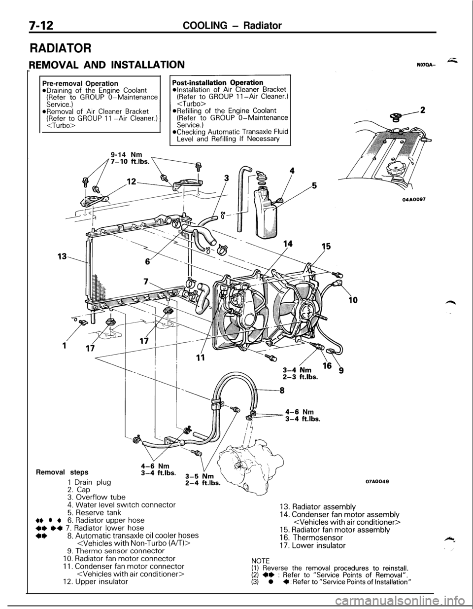
4-6 Nm3-4 ft.lbs.Removal steps
1 Drain plug2. Cap3. Overflow tube.
4-9 Nm3-4 ft.lbs.
4. Water level switch connector
5. Reserve tank~~ l +6. Radiator upper hose
+e e+ 7. Radiator lower hose
*I)8. Automatic transaxle oil cooler hoses
11. Condenser fan motor connector
04AOOS7
07A0049
13. Radiator assembly14. Condenser fan motor assembly
16. Thermosensor
17. Lower insulator
NOTE(1) Reverse the removal procedures to reinstall.(2) +e : Refer to “Service Points of Removal”.(3) l + : Refer to “Service Points of Installation”
Page 261 of 1216
COOLING- Radiator7-13Mating
marks
04A0020
SERVICE POINTS OF REMOVALN07QBAH
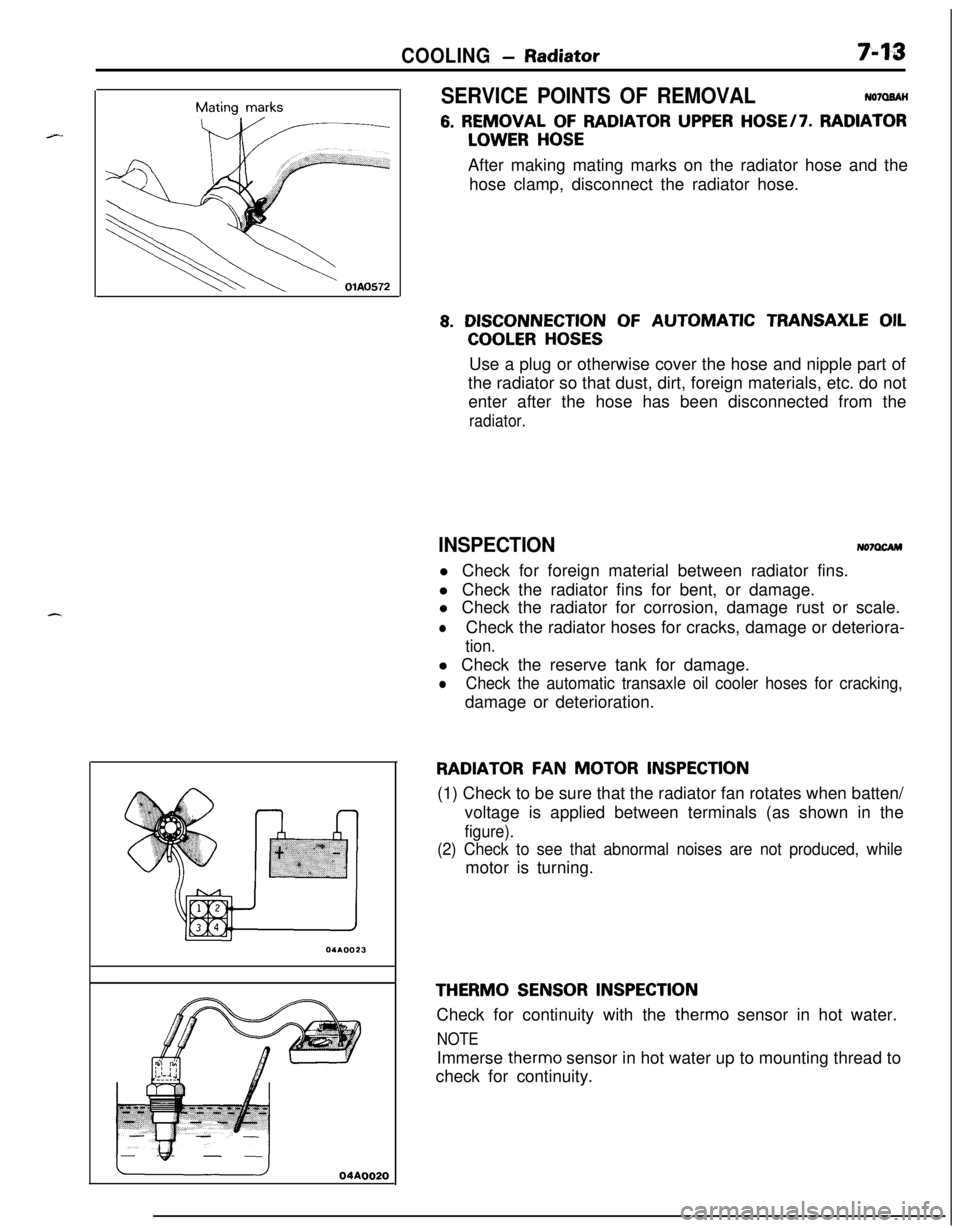
6. REMOVAL OF RADIATOR UPPER HOSE/7. RADIATOR
LOWER HOSEAfter making mating marks on the radiator hose and the
hose clamp, disconnect the radiator hose.
8. DISCONNECTION OF AUTOMATIC TRANSAXLE OIL
COOLER HOSESUse a plug or otherwise cover the hose and nipple part of
the radiator so that dust, dirt, foreign materials, etc. do not
enter after the hose has been disconnected from the
radiator.
INSPECTIONNo7OcAMl Check for foreign material between radiator fins.
l Check the radiator fins for bent, or damage.
l Check the radiator for corrosion, damage rust or scale.
lCheck the radiator hoses for cracks, damage or deteriora-
tion.l Check the reserve tank for damage.
lCheck the automatic transaxle oil cooler hoses for cracking,damage or deterioration.
RADIATOR FAN MOTOR INSPECTION(1) Check to be sure that the radiator fan rotates when batten/
voltage is applied between terminals (as shown in the
figure).
(2) Check to see that abnormal noises are not produced, whilemotor is turning.
THERM0 SENSOR INSPECTIONCheck for continuity with the therm0 sensor in hot water.
NOTEImmerse therm0 sensor in hot water up to mounting thread to
check for continuity.
Page 267 of 1216
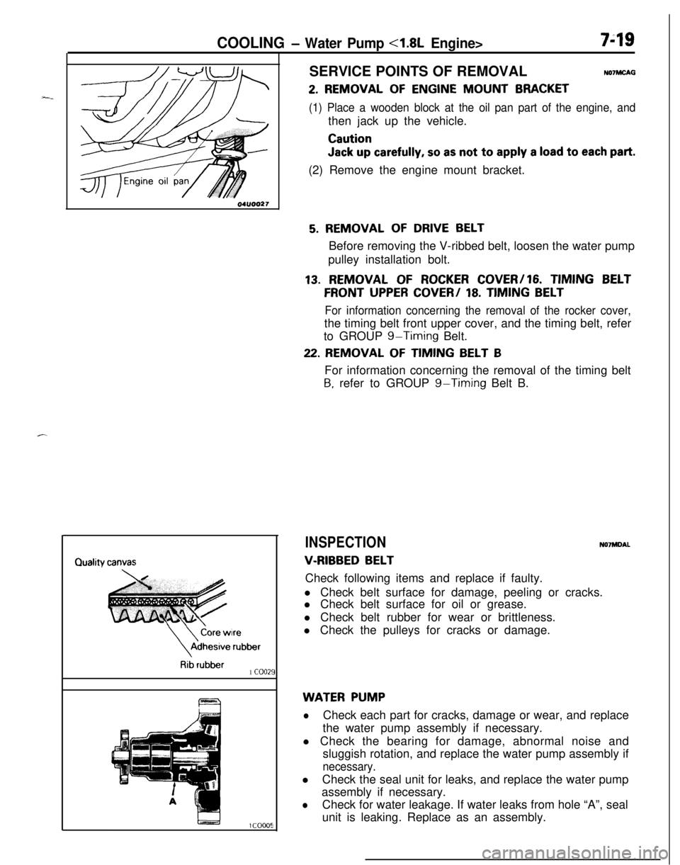
COOLING - Water Pump <1.8L Engine>749SERVICE POINTS OF REMOVAL
NO’IMCAG
2. REMOVAL OF ENGINE MOUNT BRACKET
(1) Place a wooden block at the oil pan part of the engine, andthen jack up the vehicle.
Caution
Jack up carefully, so as not to apply a load to each part.(2) Remove the engine mount bracket.
\
\
Core wireAdhesive
rubber
Rib rubber1 coo21
5. REMOVAL OF DRIVE BELTBefore removing the V-ribbed belt, loosen the water pump
pulley installation bolt.
13. REMOVAL OF ROCKER COVER/16. TIMING BELT
FRONT UPPER COVER/ 18. TIMING BELT
For information concerning the removal of the rocker cover,the timing belt front upper cover, and the timing belt, refer
to GROUP
g-Timing Belt.
22. REMOVAL OF TIMING BELT BFor information concerning the removal of the timing belt
B, refer to GROUP g-Timing Belt B.
INSPECTIONN07MDAL
V-RIBBED BELTCheck following items and replace if faulty.
l Check belt surface for damage, peeling or cracks.
l Check belt surface for oil or grease.
l Check belt rubber for wear or brittleness.
l Check the pulleys for cracks or damage.
WATER PUMP
lCheck each part for cracks, damage or wear, and replace
the water pump assembly if necessary.
l Check the bearing for damage, abnormal noise and
sluggish rotation, and replace the water pump assembly if
necessary.lCheck the seal unit for leaks, and replace the water pump
assembly if necessary.
lCheck for water leakage. If water leaks from hole “A”, seal
unit is leaking. Replace as an assembly.
Page 268 of 1216

7-20COOLING - Water Pump <1.8L Engine>
aWater pump*<
l-----r,//
O-ringWater
pipe
04ROO24Identification
mark04lJoo25Alternater
brace
404uoo22
J
SERVICE POINTS OF INSTALLATIONN07ME40a
26. INSTALLATION OF O-RINGsInsert the O-ring to the water inlet pipe, and coat the,buter
circumference of the O-ring with water.,
By coating with water, the insertion to the water pump will
become easier.
Caution
1.Care must be taken not to permit engine oil or other
greases to adhere to the O-ring.
2.When inserting the pipe, check to be sure,that there
is no sand, dirt, etc. on its inner surface.
24. INSTALLATION OF WATER PUMP,
(1) Clean both gasket surfaces of water pump body and
cylinder block.
(2) Install new water pump gasket and water pump
assembly and tighten the bolts.
Bolt diameter (d)Torque
x length (e) mm (in.)Nm (ftlbs.)I
I I148 x 28 (.31 x 1.1)112-15 (9-10) 1
I I2
71 8 x 70 (.31 x 2.76) 120-27 (15-19)(
348x55(.31x2.17)12-15(9-10)
448x28(.31x1.1)I
22. INSTALLATION OF TIMING BELT B/20. FLANGE-For information concerning the installation of the timing
belt
B and the flange, refer to GROUP g-Timing Belt B.
18. INSTALLATION OF TIMING BELT/l7. TIMING BELT
FRONT LOWER COVER/lG. TIMING BELT FRONT UP-
PERCOVER/ 15. SEMI-CIRCULARPACKING / 13.
ROCKER COVERFor information concerning the installation of the timing
belt, the timing belt front lower cover, the timing belt front
upper cover, the semi-circular packing, and the rocker
cover, refer to GROUP
g-Timing Belt.
5. DRIVE BELT TENSION ADJUSTMENT
Refer to
P.7-9.
4. DRIVE BELT TENSION ADJUSTMENT
Refer to GROUP
19-Service Adjustment Procedures.
3. DRIVEBELTTENSIONADJUSTMENT
Refer to GROUP
24-Service Adjustment Procedures,