Page 2388 of 4087

The EFI system is composed of three basic sub±systems: Fuel, Air Induction and Elect\
ronic Control
Systems.
FUEL SYSTEM
An electric pump fuel pressure supplies sufficient fuel, under a constant pressure, to the EFI injectors. In
accordance with signals from the ECU (Electronic Control Unit), these \
injectors inject the quantity of fuel most
appropriate for the engine condition into the intake manifold.
AIR INDUCTION SYSTEM
The air induction system provides sufficient air for engine operation.
ELECTRONIC CONTROL SYSTEM
The 1UZ±FE engine (ECU±formerly EFI computer) with a microcomputer \
centrally controls the EFI, ESA,
ISC and Diagnosis system, etc. The ECU controls the following functions:
1. Electronic Fuel Injection (EFI)
The ECU receives signals from various sensors indicating changing engine op\
eration conditions such as:Intake air volume
Intake air temperature
Coolant temperature
Engine rpm
Acceleration/deceleration
Exhaust oxygen content etc.
The signals are utilized by the ECU to determine the injection duration nec\
essary for an optimum air±fuel
ratio.
2. Electronic Spark Advance (ESA) The ECU is programmed with data for optimum ignition timing under any and all opera\
ting conditions. Using
data provided by sensors which monitor various engine functions (rpm, coola\
nt temperature, etc.), the
Electronic Control Unit (ECU) triggers the spark at precisely right instant. (S\
ee IG section)
3. Idle Speed Control (ISC) The ECU is programmed with idle speed data for various engine conditions (\
coolant temperature, air condi-
tioner ON/OFF, etc.).
The air volume flowing through the throttle valve by±pass passage is adj\
usted according to the signal from
each sensor and the idle speed is kept at the set value.
4. Diagnosis Function When the ECU detects any malfunctions or abnormalities in the sensor network\
, it lights the ºCHECKº en-
gine warning light in the combination meter. At the same time, the trouble is identified and a diagnostic code
is recorded by the ECU. The diagnostic code can be read by the number of\
blinks of the ºCHECKº engine
warning light when terminals TE1 and E1 are connected. The diagnostic co\
des are refer to the later page.
(See TR section)
5. Self±Correction Function If any sensor malfunctions, an average value recorded in the back±up ci\
rcuit is substituted to make driving
possible.
If danger is predicted, the engine is stopped and the ºCHECKº engine\
warning light will light up.
6. Fail±Safe Function Even if an abnormality occurs in the ECU, the back±up circuit uses a specifie\
d fuel injection and ignition
timing to provide vehicle driveability, and also lightsup the ºCHECKº engine warning light.
FI±4
EFI SYSTEM
± Description
WhereEverybodyKnowsYourName
Page 2391 of 4087
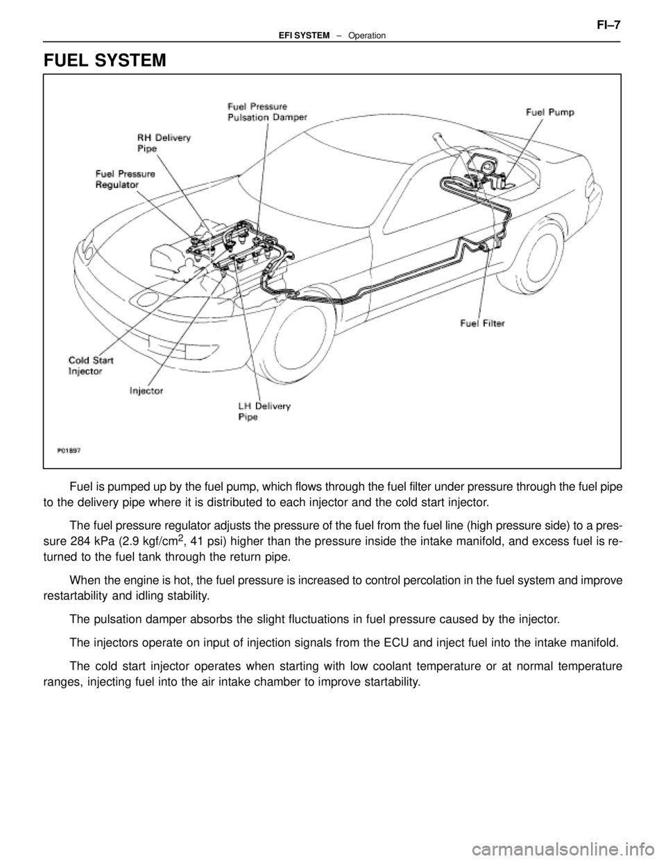
FUEL SYSTEM
Fuel is pumped up by the fuel pump, which flows through the fuel filter under pr\
essure through the fuel pipe
to the delivery pipe where it is distributed to each injector and the cold\
start injector.
The fuel pressure regulator adjusts the pressure of the fuel from the fuel \
line (high pressure side) to a pres-
sure 284 kPa (2.9 kgf/cm
2, 41 psi) higher than the pressure inside the intake manifold, and exce\
ss fuel is re-
turned to the fuel tank through the return pipe.
When the engine is hot, the fuel pressure is increased to control percolatio\
n in the fuel system and improve
restartability and idling stability.
The pulsation damper absorbs the slight fluctuations in fuel pressure ca\
used by the injector.
The injectors operate on input of injection signals from the ECU and inj\
ect fuel into the intake manifold.
The cold start injector operates when starting with low coolant temperature or at normal temperature
ranges, injecting fuel into the air intake chamber to improve startability. FI±7
EFI SYSTEM
± Operation
WhereEverybodyKnowsYourName
Page 2396 of 4087
PRECAUTIONS
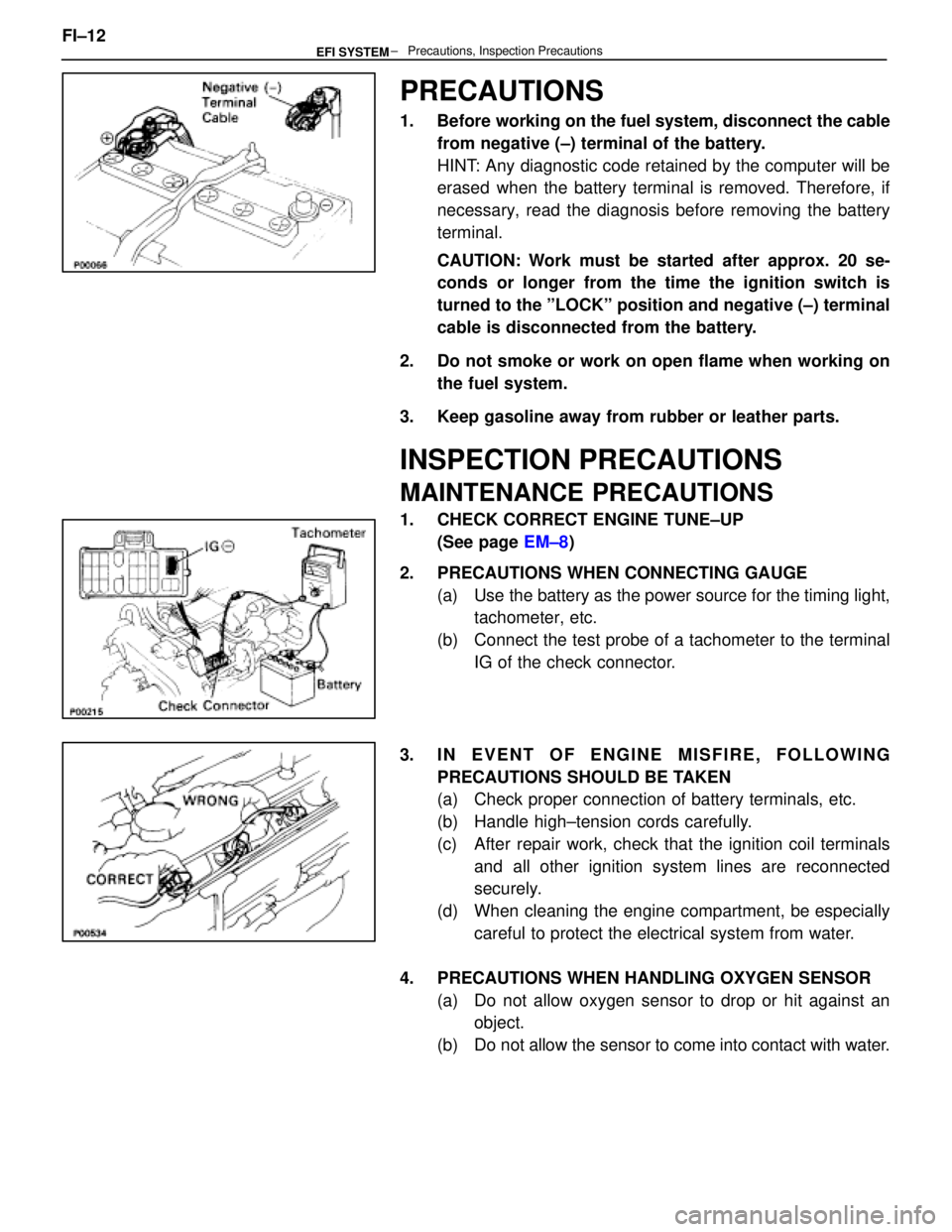
1. Before working on the fuel system, disconnect the cablefrom negative (±) terminal of the battery.
HINT: Any diagnostic code retained by the computer will be
erased when the battery terminal is removed. Therefore, if
necessary, read the diagnosis before removing the battery
terminal.
CAUTION: Work must be started after approx. 20 se-
conds or longer from the time the ignition switch is
turned to the ºLOCKº position and negative (±) terminal
cable is disconnected from the battery.
2. Do not smoke or work on open flame when working on the fuel system.
3. Keep gasoline away from rubber or leather parts.
INSPECTION PRECAUTIONS
MAINTENANCE PRECAUTIONS
1. CHECK CORRECT ENGINE TUNE±UP (See page EM±8)
2. PRECAUTIONS WHEN CONNECTING GAUGE (a) Use the battery as the power source for the timing light,tachometer, etc.
(b) Connect the test probe of a tachometer to the terminal IG of the check connector.
3. IN EVENT OF ENGINE MISFIRE, FOLLOWING PRECAUTIONS SHOULD BE TAKEN
(a) Check proper connection of battery terminals, etc.
(b) Handle high±tension cords carefully.
(c) After repair work, check that the ignition coil terminalsand all other ignition system lines are reconnected
securely.
(d) When cleaning the engine compartment, be especially careful to protect the electrical system from water.
4. PRECAUTIONS WHEN HANDLING OXYGEN SENSOR (a) Do not allow oxygen sensor to drop or hit against anobject.
(b) Do not allow the sensor to come into contact with water.
FI±12
± Precautions, Inspection PrecautionsEFI SYSTEM
WhereEverybodyKnowsYourName
Page 2425 of 4087
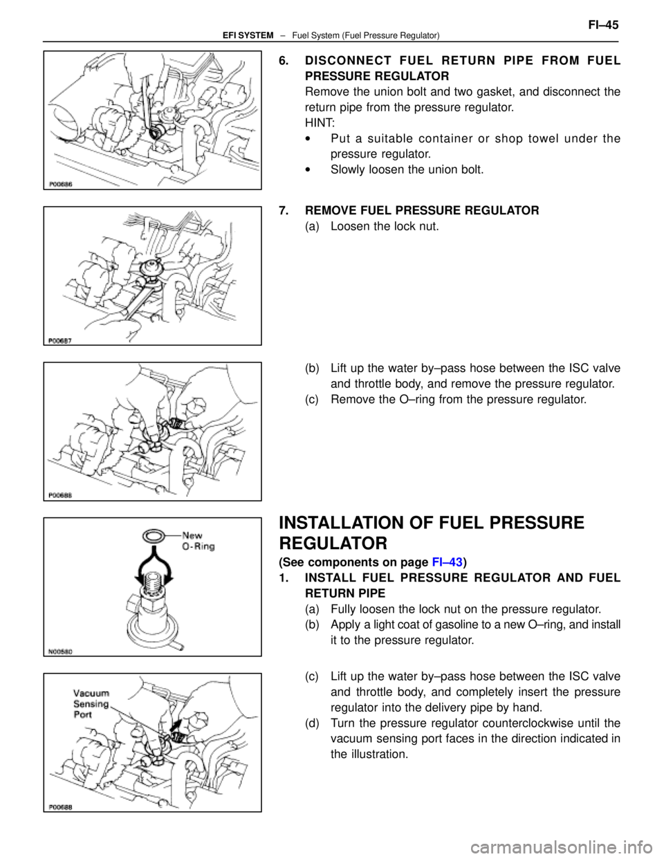
6. DISCONNECT FUEL RETURN PIPE FROM FUELPRESSURE REGULATOR
Remove the union bolt and two gasket, and disconnect the
return pipe from the pressure regulator.
HINT:
wPut a suitable container or shop towel under the
pressure regulator.
w Slowly loosen the union bolt.
7. REMOVE FUEL PRESSURE REGULATOR (a) Loosen the lock nut.
(b) Lift up the water by±pass hose between the ISC valveand throttle body, and remove the pressure regulator.
(c) Remove the O±ring from the pressure regulator.
INSTALLATION OF FUEL PRESSURE
REGULATOR
(See components on page FI±43)
1. INSTALL FUEL PRESSURE REGULATOR AND FUEL RETURN PIPE
(a) Fully loosen the lock nut on the pressure regulator.
(b) Apply a light coat of gasoline to a new O±ring, and install
it to the pressure regulator.
(c) Lift up the water by±pass hose between the ISC valve and throttle body, and completely insert the pressure
regulator into the delivery pipe by hand.
(d) Turn the pressure regulator counterclockwise until the vacuum sensing port faces in the direction indicated in
the illustration. FI±45
EFI SYSTEM
± Fuel System (Fuel Pressure Regulator)
WhereEverybodyKnowsYourName
Page 2434 of 4087
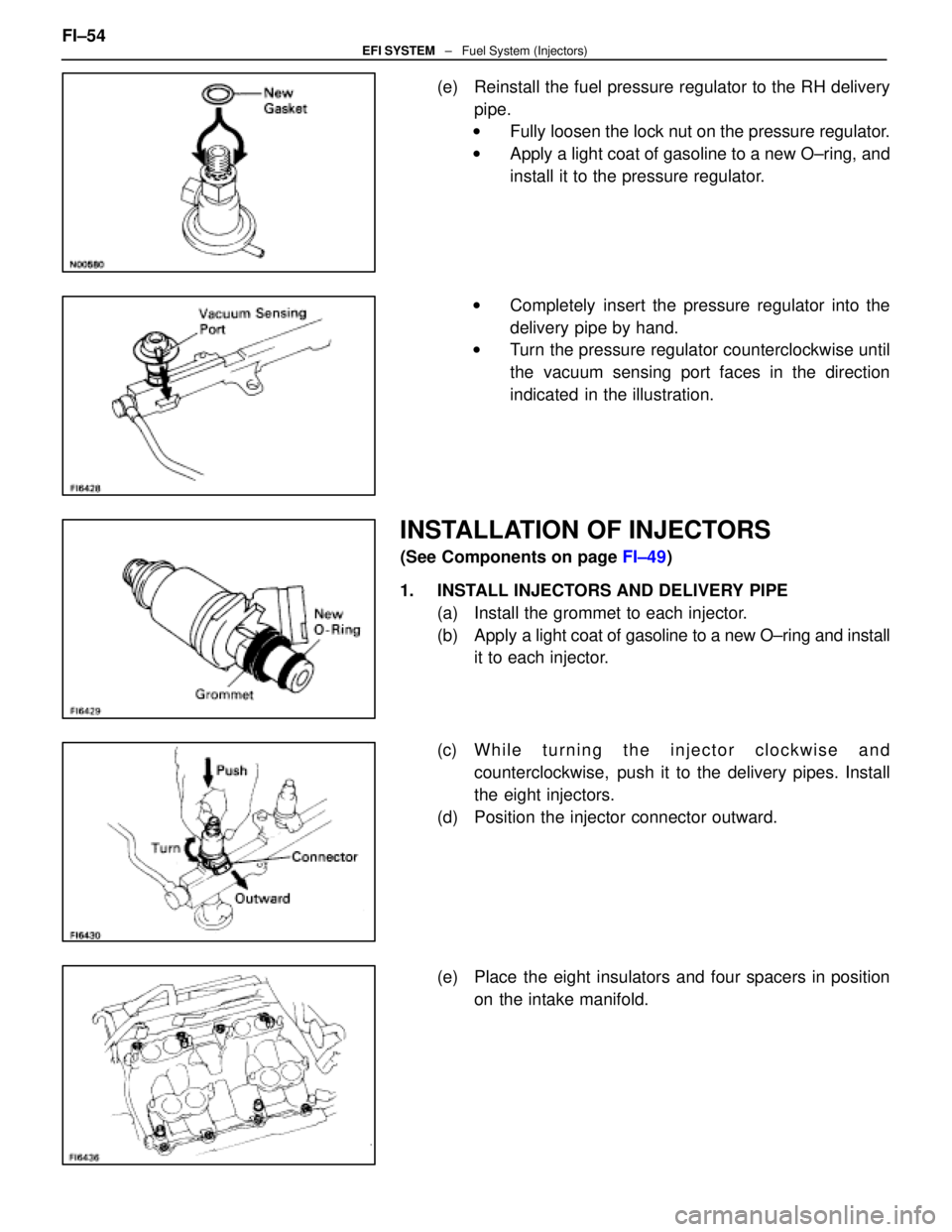
(e) Reinstall the fuel pressure regulator to the RH deliverypipe.
w Fully loosen the lock nut on the pressure regulator.
w Apply a light coat of gasoline to a new O±ring, and
install it to the pressure regulator.
w Completely insert the pressure regulator into the
delivery pipe by hand.
w Turn the pressure regulator counterclockwise until
the vacuum sensing port faces in the direction
indicated in the illustration.
INSTALLATION OF INJECTORS
(See Components on page FI±49)
1. INSTALL INJECTORS AND DELIVERY PIPE (a) Install the grommet to each injector.
(b) Apply a light coat of gasoline to a new O±ring and install
it to each injector.
(c) W h i l e t u r n i n g t h e i n j e c t o r c l o c k w i s e a n d counterclockwise, push it to the delivery pipes. Install
the eight injectors.
(d) Position the injector connector outward.
(e) Place the eight insulators and four spacers in position on the intake manifold.
FI±54
EFI SYSTEM
± Fuel System (Injectors)
WhereEverybodyKnowsYourName
Page 2506 of 4087
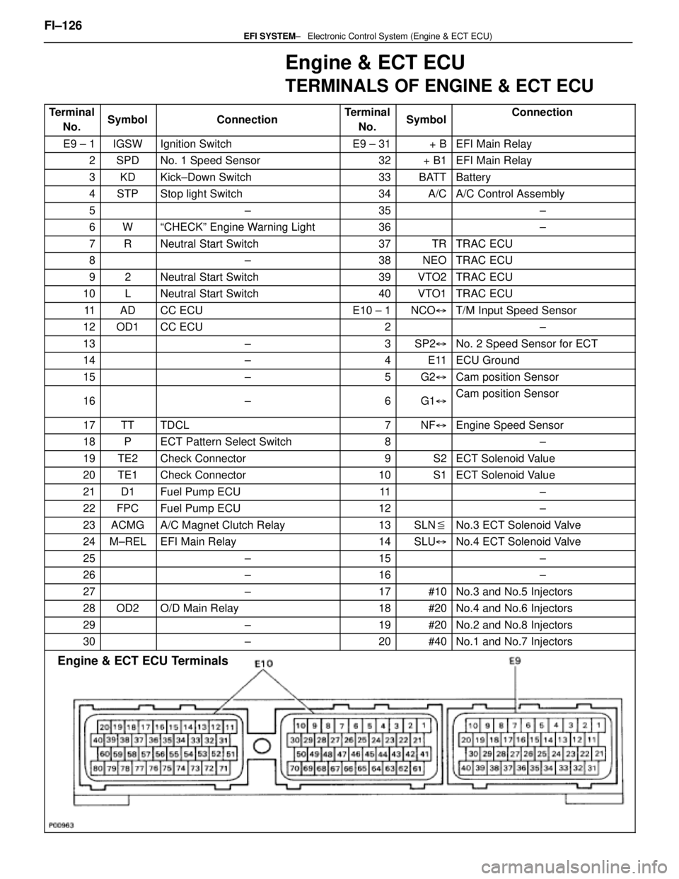
Engine & ECT ECU
TERMINALS OF ENGINE & ECT ECU
TerminalNo.SymbolConnectionTerminalNo.SymbolConnection
E9 ± 1IGSWIgnition SwitchE9 ± 31+ BEFI Main Relay
2SPDNo. 1 Speed Sensor32+ B1EFI Main Relay
3KDKick±Down Switch33BATTBattery
4STPStop light Switch34A/CA/C Control Assembly
5±35±
6WªCHECKº Engine Warning Light36±
7RNeutral Start Switch37TRTRAC ECU
8±38NEOTRAC ECU
92Neutral Start Switch39VTO2TRAC ECU
10LNeutral Start Switch40VTO1TRAC ECU
11ADCC ECUE10 ± 1NCO �T/M Input Speed Sensor
12OD1CC ECU2±
13±3SP2�No. 2 Speed Sensor for ECT
14±4E11ECU Ground
15±5G2�Cam position Sensor
16±6G1�Cam position Sensor
17TTTDCL7NF�Engine Speed Sensor
18PECT Pattern Select Switch8±
19TE2Check Connector9S2ECT Solenoid Value
20TE1Check Connector10S1ECT Solenoid Value
21D1Fuel Pump ECU11±
22FPCFuel Pump ECU12±
23ACMGA/C Magnet Clutch Relay13SLN �No.3 ECT Solenoid Valve
24M±RELEFI Main Relay14SLU�No.4 ECT Solenoid Valve
25±15±
26±16±
27±17#10No.3 and No.5 Injectors
28OD2O/D Main Relay18#20No.4 and No.6 Injectors
29±19#20No.2 and No.8 Injectors
30±20#40No.1 and No.7 Injectors
Engine & ECT ECU Terminals
FI±126 ± Electronic Control \
System (Engine & ECT ECU)EFI SYSTEM
WhereEverybodyKnowsYourName
Page 2539 of 4087
wAlign the spline of the ignition coil with the spline of
the holder, and slide on the holder.
NOTICE: Check that holder is correctly installed to the
grommet and ignition coil as shown in the illustration. w Check that the lock claw of the holder is engaged
by lightly pulling the holder.
5. INSTALL RH NO.3 TIMING BELT COVER (a) Install the three gaskets to the timing belt cover.
(b) Fit portion A of the timing belt cover, matching it with the
lower high±tension cord cover.
(c) Install the timing belt cover with the three bolts.
±
IGNITION SYSTEM High±Tension Cords and Cord ClampsIG±17
WhereEverybodyKnowsYourName
Page 2550 of 4087
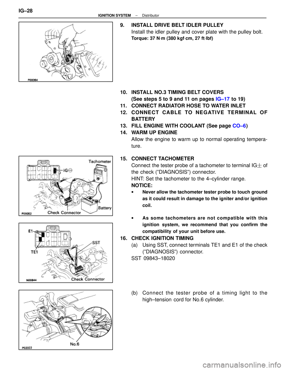
9. INSTALL DRIVE BELT IDLER PULLEYInstall the idler pulley and cover plate with the pulley bolt.
Torque: 37 N Vm (380 kgf Vcm, 27 ft Vlbf)
10. INSTALL NO.3 TIMING BELT COVERS
(See steps 5 to 9 and 11 on pages IG±17 to 19)
11. CONNECT RADIATOR HOSE TO WATER INLET
12. C O N N E C T C A B L E TO N E G AT I V E T E R M I N A L O F BATTERY
13. FILL ENGINE WITH COOLANT (See page CO±6)
14. WARM UP ENGINE Allow the engine to warm up to normal operating tempera-
ture.
15. CONNECT TACHOMETER Connect the tester probe of a tachometer to terminal IG � of
the check (ºDIAGNOSISº) connector.
HINT: Set the tachometer to the 4±cylinder range.
NOTICE:
w Never allow the tachometer tester probe to touch ground
as it could result in damage to the igniter and/or ignition
coil.
w As some tachometers are not compatible with this
ignition system, we recommend that you confirm the
compatibility of your unit before use.
16. CHECK IGNITION TIMING
(a) Using SST, connect terminals TE1 and E1 of the check(ºDIAGNOSISº) connector.
SST 09843±18020
(b) C onnect the tester probe of a timing light to the
high±tension cord for No.6 cylinder.
IG±28
±
IGNITION SYSTEM Distributor
WhereEverybodyKnowsYourName