Page 2145 of 4087
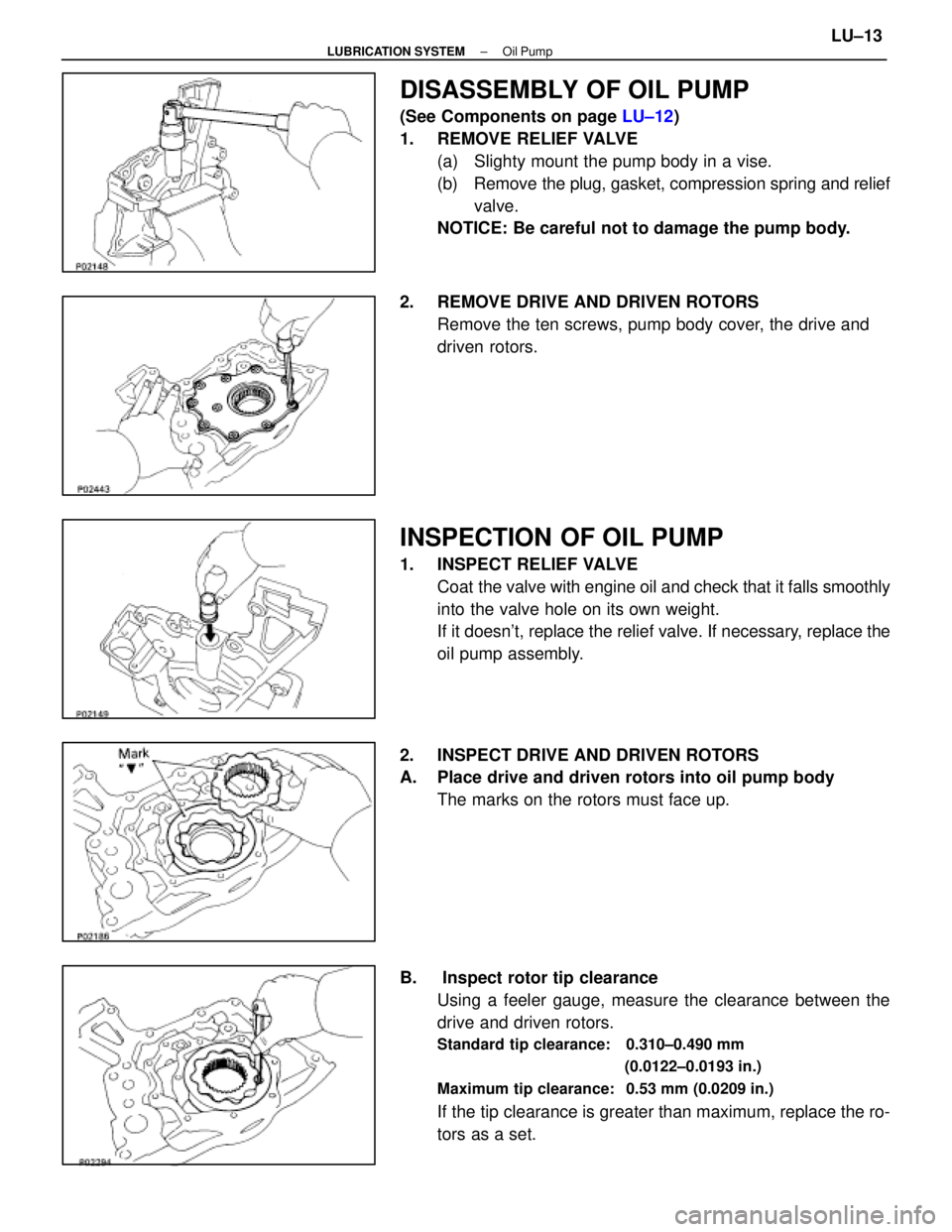
DISASSEMBLY OF OIL PUMP
(See Components on page LU±12)
1. REMOVE RELIEF VALVE (a) Slighty mount the pump body in a vise.
(b) Remove the plug, gasket, compression spring and reliefvalve.
NOTICE: Be careful not to damage the pump body.
2. REMOVE DRIVE AND DRIVEN ROTORS Remove the ten screws, pump body cover, the drive and
driven rotors.
INSPECTION OF OIL PUMP
1. INSPECT RELIEF VALVECoat the valve with engine oil and check that it falls smoothly
into the valve hole on its own weight.
If it doesn't, replace the relief valve. If necessary, replace the
oil pump assembly.
2. INSPECT DRIVE AND DRIVEN ROTORS
A. Place drive and driven rotors into oil pump body The marks on the rotors must face up.
B. Inspect rotor tip clearance Using a feeler gauge, measure the clearance between the
drive and driven rotors.
Standard tip clearance: 0.310±0.490 mm
(0.0122±0.0193 in.)
Maximum tip clearance: 0.53 mm (0.0209 in.)
If the tip clearance is greater than maximum, replace the ro-
tors as a set.
±
LUBRICATION SYSTEM Oil PumpLU±13
WhereEverybodyKnowsYourName
Page 2147 of 4087
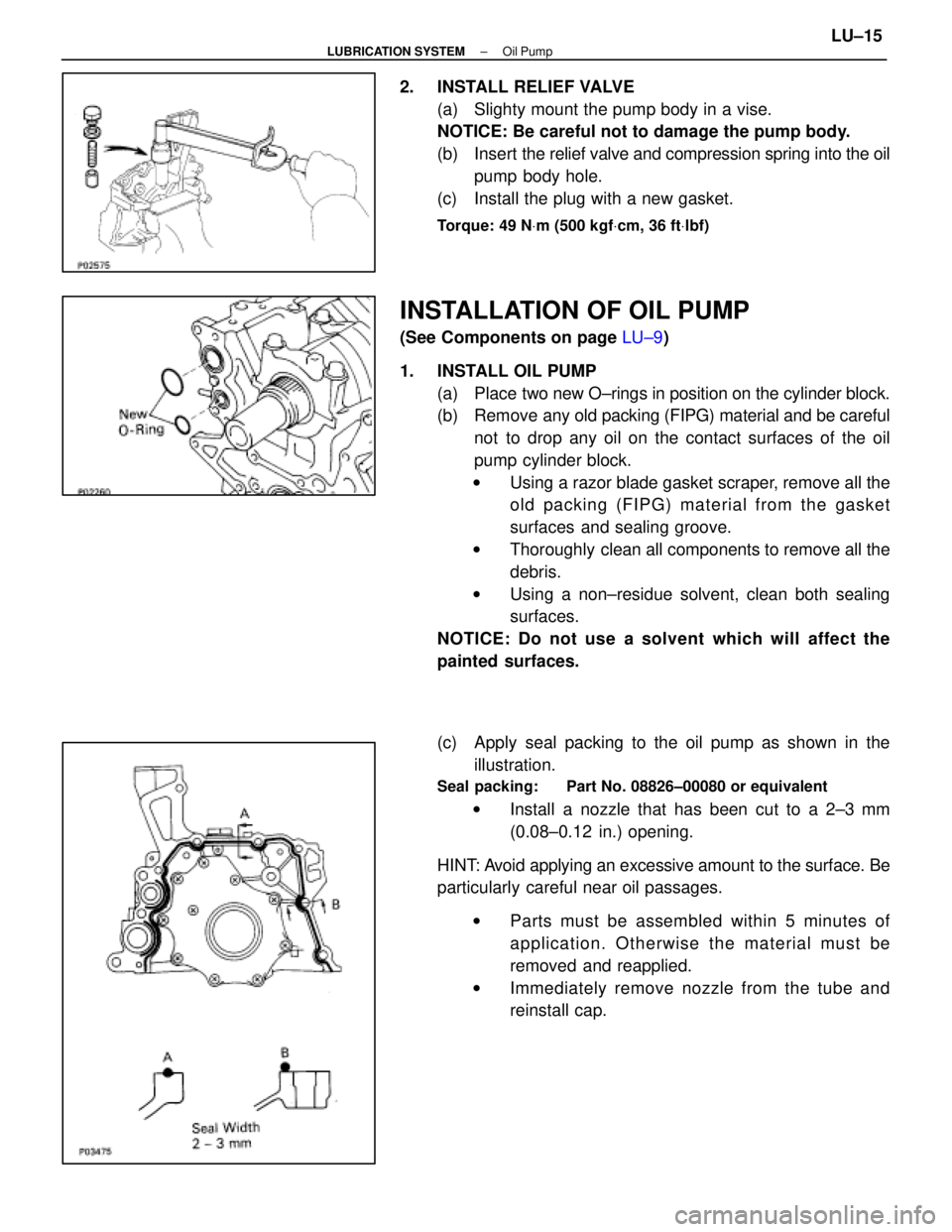
2. INSTALL RELIEF VALVE(a) Slighty mount the pump body in a vise.
NOTICE: Be careful not to damage the pump body.
(b) Insert the relief valve and compression spring into the oil
pump body hole.
(c) Install the plug with a new gasket.
Torque: 49 N Vm (500 kgf Vcm, 36 ft Vlbf)
INSTALLATION OF OIL PUMP
(See Components on page LU±9)
1. INSTALL OIL PUMP (a) Place two new O±rings in position on the cylinder block.
(b) Remove any old packing (FIPG) material and be careful
not to drop any oil on the contact surfaces of the oil
pump cylinder block.
w Using a razor blade gasket scraper, remove all the
old packing (FIPG) material from the gasket
surfaces and sealing groove.
w Thoroughly clean all components to remove all the
debris.
w Using a non±residue solvent, clean both sealing
surfaces.
NOTICE: Do not use a solvent which will affect the
painted surfaces.
(c) Apply seal packing to the oil pump as shown in the illustration.
Seal packing: Part No. 08826±00080 or equivalent
w Install a nozzle that has been cut to a 2±3 mm
(0.08±0.12 in.) opening.
HINT: Avoid applying an excessive amount to the surface. Be
particularly careful near oil passages. w Parts must be assembled within 5 minutes of
application. Otherwise the material must be
removed and reapplied.
w Immediately remove nozzle from the tube and
reinstall cap.
±
LUBRICATION SYSTEM Oil PumpLU±15
WhereEverybodyKnowsYourName
Page 2162 of 4087
MA04N±01
BRAKES
13. INSPECT BRAKE LINE PIPES AND HOSESHINT: Check in a well lighted area. Check the entire circum-
ference and length of the brake hoses using a mirror as re-
quired. Turn the front whe els fully right or left before checking
the front brake.
(a) Check all brake lines and hoses for: wDamage
w Wear
w Deformation
w Cracks
w Corrosion
w Leaks
w Bends
w Twists
(b) Check all clamps for tightness and connections for leakage.
(c) Check that the hoses and lines are clear of sharp edges, moving parts and the exhaust system.
(d) Check that the lines installed in grommets pass through the center of the grommets.
±
MAINTENANCE (1UZ ± FE)MA±11
WhereEverybodyKnowsYourName
Page 2164 of 4087

(b) Check the brake drums for scoring or wear.
Maximum drum inside diameter:191 mm (7.520 in.)
(c) Clean the brake parts with a damp cloth.NOTICE: Do not use compressed air to clean the brake
parts.
(d) Seat the parking brake shoes during the road test (item 25) in do the following:
wDrive the vehicle at approx. 50 km/h (30 mph) on a safe,
level and dry road.
w With the parking brake release buttom pushed in, pull on
the lever with 88 N (9 kgf, 20 lbf) of force.
w Drive the vehicle for approx. 400 meters (1/4 mile) in this
condition.
w Repeat this procedure 2 or 3 times.
w Check parking pedal travel.
If necessary, adjust the parking brake.
16. INSPECT AND CHANGE BRAKE FLUID
(a) Visually inspect the master cylinder for leaks.
(b) Change brake fluid (See BR section)
Fluid: SAE J1703 or FMVSS No.116 DOT3
MA04F±01
CHASSIS
17. INSPECT STEERING LINKAGE
(a) Check the steering wheel freeplay.
Maximum freeplay:30 mm (1.18 in.)
With the vehicle stopped and pointed straight ahead, rock the
steering wheel gently back and forth with light finger pres-
sure.
(b) Check the steering linkage for looseness or damage. Check that:
wTie rod ends do not have excessive play.
w Dust seals and boots are not damaged.
w Boot clamps are not loose.
±
MAINTENANCE (1UZ ± FE)MA±13
WhereEverybodyKnowsYourName
Page 2170 of 4087

GENERAL MAINTENANCE
MA00M±03
There are the maintenance and inspection
items which are considered to be the owner's
responsibility. They can be performed by the
owner or be can have them done at a service
shop. These items include those which should
be checked on a daily basis, those which, in
most cases, do not require (special) tools and
those which are considered to be reasonable
for the owner to perform. Items and procedures
for general maintanance are as follows:
MA00P±04
OUTSIDE VEHICLE
1. TIRES
(a) Check the pressure with a gauge. Adjust ifnecessary.
(b) Check for cuts, damage or excessive wear.
2. WHEEL NUTS Wheel checking the tires, check the nuts for
looseness or for missing nuts. If necessary,
tighten them.
3. TIRE ROTATION It is recommended that tires be rotated every
12,000 km (7,500 miles).
4. WINDSHIELD WIPER BLADES Check for wear or cracks whenever they do not
wipe clean. Replace if necessary.
5. FLUID LEAKS
(a) Check underneath for leaking fuel, oil, water or
other fluid.
(b) If you smell gasoline fumes or notice any leak, have the cause found and corrected.
6. DOORS AND ENGINE HOOD
(a) Check that all doors including the trunk lid operate smoothly, and that all latches lock
securely.
(b) Check that the engine hood secondary latch secures the hood from opening when the
primary latch is released.
MA00R±05
INSIDE VEHICLE
7. LIGHTS
(a) C h e c k t h a t t h e h eadlights, stop lights,
tail±lights, turn signal lights, and other lights
are all working. (b) Check the headlight aiming.
8. WARNING LIGHT AND BUZZERS
Check that all warning lights and buzzers func-
tion properly.
9. HORN Check that it is working.
10. WINDSHIELD GLASS
Check for scratches, pits or abrasions.
11. WINDSHIELD WIPER AND WASHER
(a) Check operation of the wipers and washer.
(b) Check that the wipers do not streak.
12. WINDSHIELD DEFROSTER Check that the air comes out from the defroster
outlet when operating the heater air condition-
er at defroster mode.
13. REAR VIEW MIRROR
Check that it is mounted securely.
14. SUN VISORS Check that they move freely and are mounted
securely.
15. STEERING WHEEL Check that it has the specified freeplay. Be
alert for changes in steering condition, such as
hard steering, excessive freeplay or strange
noise.
16. SEATS
(a) Check that all front seat controls such as seat adjusters, seatback recliner, etc. operate
smoothly.
(b) Check that all latches lock securely in any position.
(c) Check that the locks hold securely in any latched position.
(d) Check that the head restraints move up and
down smoothly and that the locks hold securely
in ay latches position.
(e) For folding±down rear seat backs, check that the latches lock securely.
17. SEAT BELTS
(a) Ch e ck th a t th e se a t be lt syste m su ch as buckles, retractors and anchors operate
properly and smoothly.
(b) Check that the belt webbing is not cut, frayed,
worn or damaged.
18. ACCELERATOR PEDAL Check the pedal for smooth operation and un-
even pedal effort or catching.
±
MAINTENANCE (1UZ ± FE)MA±19
WhereEverybodyKnowsYourName
Page 2241 of 4087
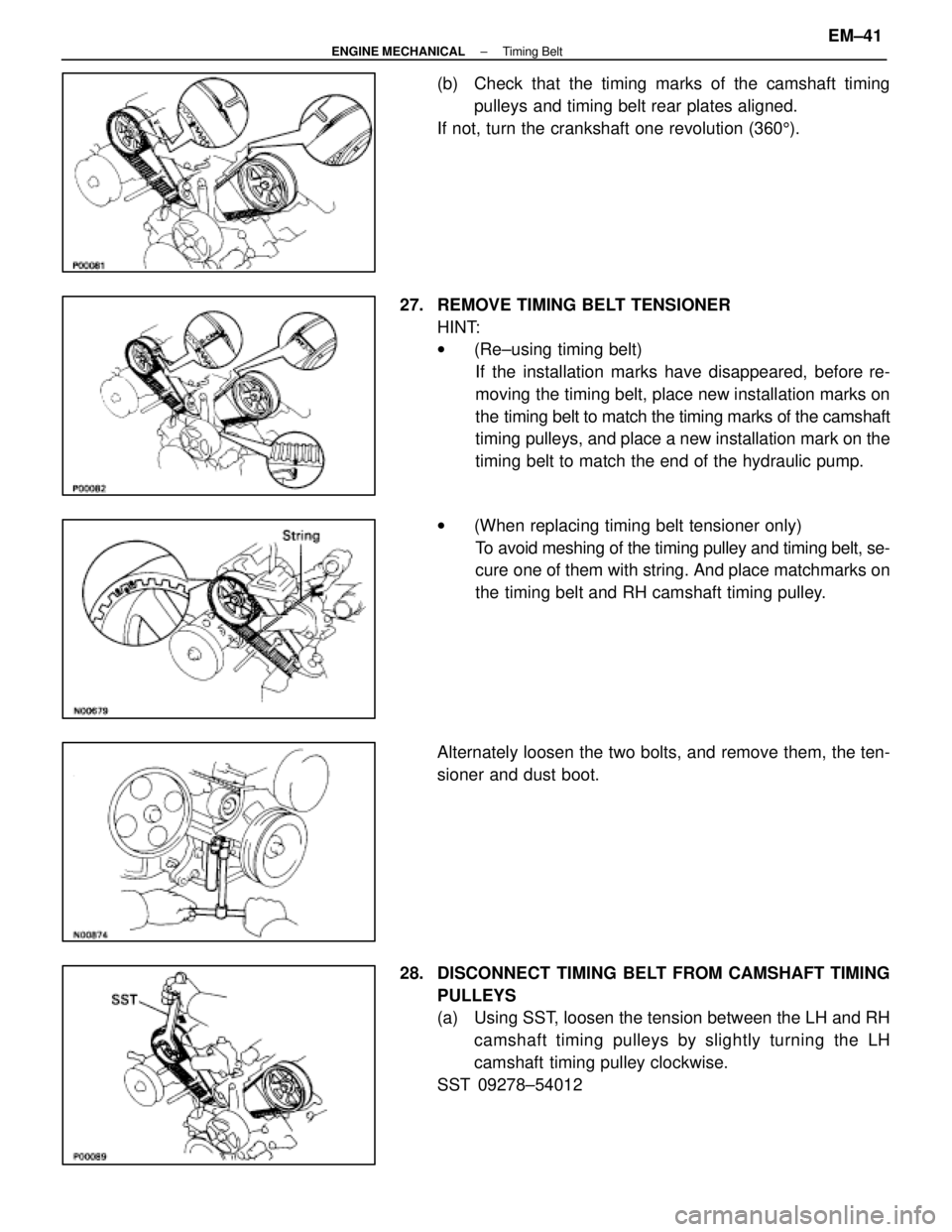
(b) Check that the timing marks of the camshaft timingpulleys and timing belt rear plates aligned.
If not, turn the crankshaft one revolution (360 5).
27. REMOVE TIMING BELT TENSIONER HINT:
w(Re±using timing belt)
If the installation marks have disappeared, before re-
moving the timing belt, place new installation marks on
the timing belt to match the timing marks of the camshaft
timing pulleys, and place a new installation mark on the
timing belt to match the end of the hydraulic pump.
w (When replacing timing belt tensioner only)
To avoid meshing of the timing pulley and timing belt, se-
cure one of them with string. And place matchmarks on
the timing belt and RH camshaft timing pulley.
Alternately loosen the two bolts, and remove them, the ten-
sioner and dust boot.
28. DISCONNECT TIMING BELT FROM CAMSHAFT TIMING PULLEYS
(a) Using SST, loosen the tension between the LH and RHcamshaft timing pulleys by slightly turning the LH
camshaft timing pulley clockwise.
SST 09278±54012
±
ENGINE MECHANICAL Timing BeltEM±41
WhereEverybodyKnowsYourName
Page 2249 of 4087
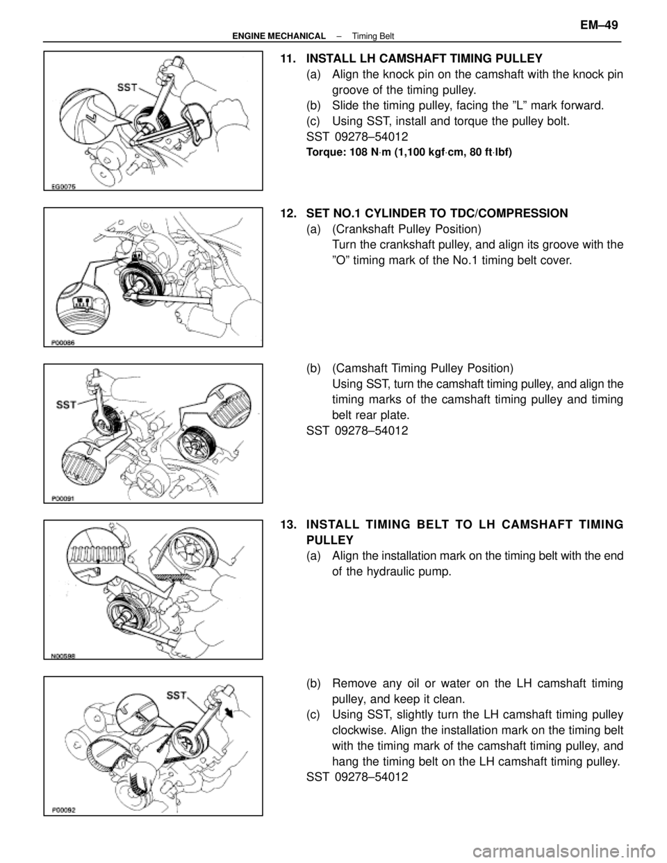
11. INSTALL LH CAMSHAFT TIMING PULLEY(a) Align the knock pin on the camshaft with the knock pingroove of the timing pulley.
(b) Slide the timing pulley, facing the ºLº mark forward.
(c) Using SST, install and torque the pulley bolt.
SST 09278±54012
Torque: 108 N Vm (1,100 kgf Vcm, 80 ft Vlbf)
12. SET NO.1 CYLINDER TO TDC/COMPRESSION
(a) (Crankshaft Pulley Position)Turn the crankshaft pulley, and align its groove with the
ºOº timing mark of the No.1 timing belt cover.
(b) (Camshaft Timing Pulley Position) Using SST, t urn the camshaft timing pulley, and align the
timing marks of the camshaft timing pulley and timing
belt rear plate.
SST 09278±54012
13. INS TALL TIMING BE LT TO LH CAMS HAFT TIMING PULLEY
(a) Align the installation mark on the timing belt with the end
of the hydraulic pump.
(b) Remove any oil or water on the LH camshaft timing pulley, and keep it clean.
(c) Using SST, slightly turn the LH camshaft timing pulley
clockwise. Align the installation mark on the timing belt
with the timing mark of the camshaft timing pulley, and
hang the timing belt on the LH camshaft timing pulley.
SST 09278±54012
±
ENGINE MECHANICAL Timing BeltEM±49
WhereEverybodyKnowsYourName
Page 2250 of 4087
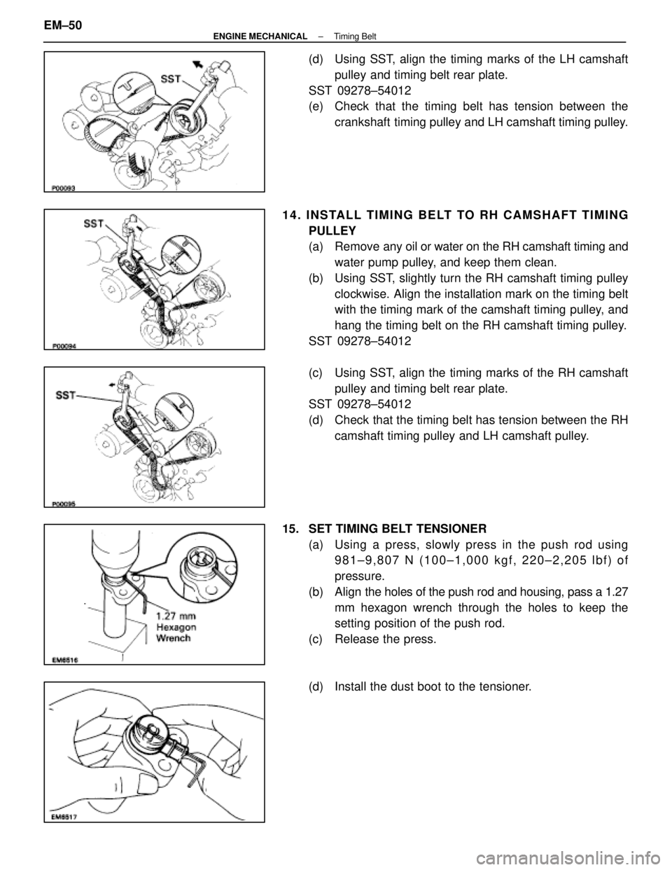
(d) Using SST, align the timing marks of the LH camshaftpulley and timing belt rear plate.
SST 09278±54012
(e) Check that the timing belt has tension between the crankshaft timing pulley and LH camshaft timing pulley.
14. INSTALL TIMING BELT TO RH CAMSHAFT TIMING PULLEY
(a) Remove any oil or water on the RH camshaft timing andwater pump pulley, and keep them clean.
(b) Using SST, slightly turn the RH camshaft timing pulley clockwise. Align the installation mark on the timing belt
with the timing mark of the camshaft timing pulley, and
hang the timing belt on the RH camshaft timing pulley.
SST 09278±54012
(c) Using SST, align the timing marks of the RH camshaft pulley and timing belt rear plate.
SST 09278±54012
(d) Check that the timing belt has tension between the RH
camshaft timing pulley and LH camshaft pulley.
15. SET TIMING BELT TENSIONER (a) Using a press, slowly press in the push rod using981±9,807 N (100±1,000 kgf, 220±2,205 lbf) of
pressure.
(b) Align the holes of the push rod and housing, pass a 1.27
mm hexagon wrench through the holes to keep the
setting position of the push rod.
(c) Release the press.
(d) Install the dust boot to the tensioner.
EM±50
±
ENGINE MECHANICAL Timing Belt
WhereEverybodyKnowsYourName