Page 2026 of 4087

FUEL SYSTEM
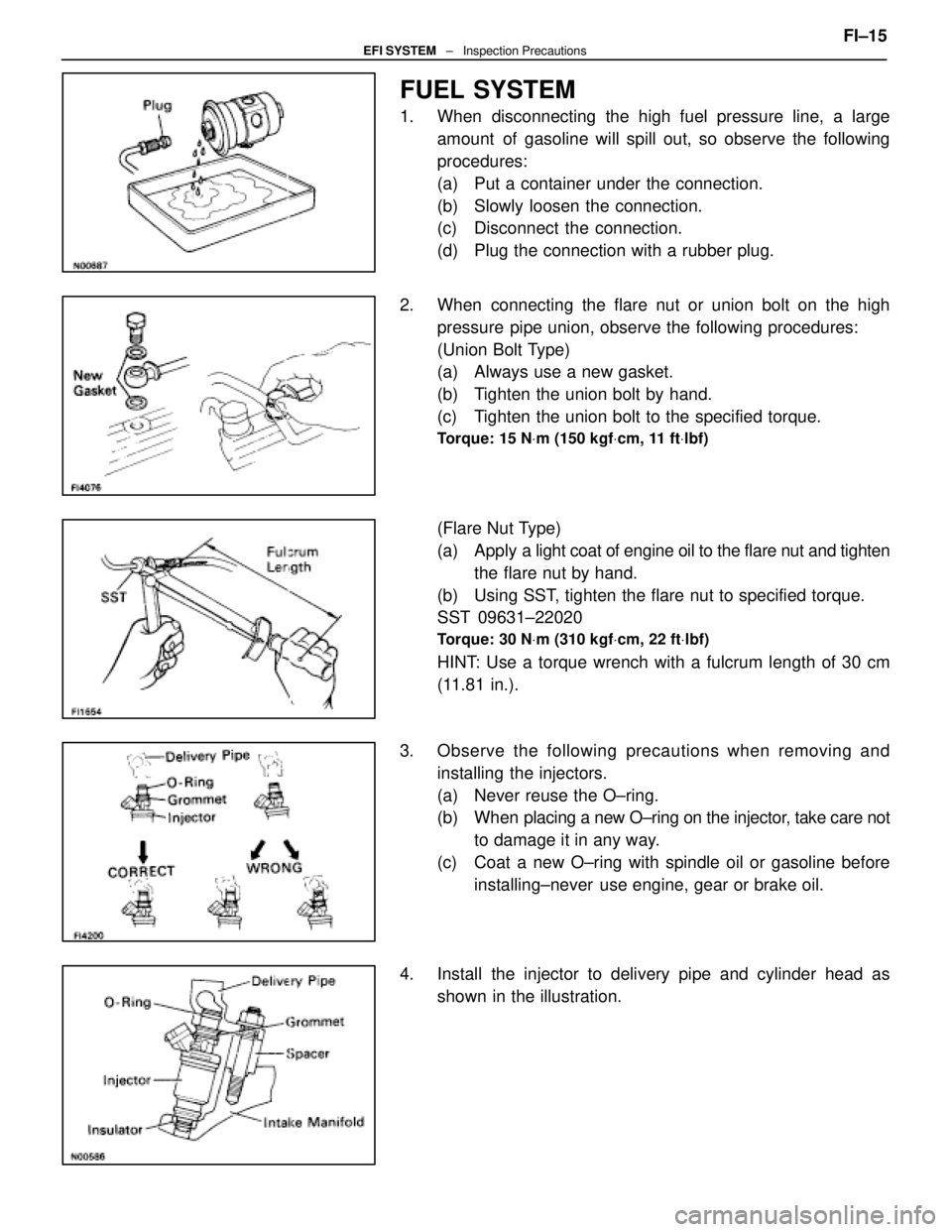
1. When disconnecting the high fuel pressure line, a largeamount of gasoline will spill out, so observe the following
procedures:
(a) Put a container under the connection.
(b) Slowly loosen the connection.
(c) Disconnect the connection.
(d) Plug the connection with a rubber plug.
2. When connecting the flare nut or union bolt on the high pressure pipe union, observe the following procedures:
(Union Bolt Type)
(a) Always use a new gasket.
(b) Tighten the union bolt by hand.
(c) Tighten the union bolt to the specified torque.
Torque: 15 N Vm (150 kgf Vcm, 11 ft Vlbf)
(Flare Nut Type)
(a) Apply a light coat of engine oil to the flare nut and tighten
the flare nut by hand.
(b) Using SST, tighten the flare nut to specified torque.
SST 09631±22020
Torque: 30 N Vm (310 kgf Vcm, 22 ft Vlbf)
HINT: Use a torque wrench with a fulcrum length of 30 cm
(11.81 in.).
3. Observe the following precautions when removing and installing the injectors.
(a) Never reuse the O±ring.
(b) When placing a new O±ring on the injector, take care not
to damage it in any way.
(c) Coat a new O±ring with spindle oil or gasoline before installing±never use engine, gear or brake oil.
4. Install the injector to delivery pipe and cylinder head as shown in the illustration. FI±15
EFI SYSTEM
± Inspection Precautions
WhereEverybodyKnowsYourName
Page 2045 of 4087
INSTALLATION OF FUEL PRESSURE
REGULATOR
(See components on page FI±24)
1. INSTALL FUEL PRESSURE REGULATOR AND FUEL RETURN PIPE
(a) Apply a light coat of gasoline to a new O±ring, and install
it to the pressure regulator.
(b) Install the pressure regulator with the two bolts.
Torque: 8.8 N Vm (90 kgf Vcm, 78 in. Vlbf)
2. CONNECT NO. 2 FUEL PIPE TO FUEL PRESSURE
REGULATOR
Connect the fuel pipe to the pressure regulator with new two
gaskets and the union bolt.
Torque: 27 N Vm (280 kgf Vcm, 20 ft Vlbf)
3. CONNECT VACUUM SENSING HOSE TO FUEL
PRESSURE REGULATOR
4. CHECK FOR FUEL LEAKS (See page FI±15)
±
EFI SYSTEM Fuel System (Fuel Pressure Regulator)FI±25
WhereEverybodyKnowsYourName
Page 2069 of 4087
(e) Install the fuel hose clamp with the two bolts.
INSTALLATION OF INJECTORS
(See Components on page FI±27)
1. INSTALL INJECTORS AND DELIVERY PIPE (a) Install the grommet to each injector.
(b) Apply a light coat of gasoline to a new O±ring and install
it to each injector.
(c) W h i l e t u r n i n g t h e i n j e c t o r c l o c k w i s e a n d counterclockwise, push it to the delivery pipe. Install the
six injectors.
(d) Position the injector connector outward.
(e) Place the six insulators and three spacers in position on
the intake manifold.
(f) Place the six injectors together with the delivery pipe in position on the cylinder head.
FI±32
±
EFI SYSTEM Fuel System (Injectors)
WhereEverybodyKnowsYourName
Page 2082 of 4087

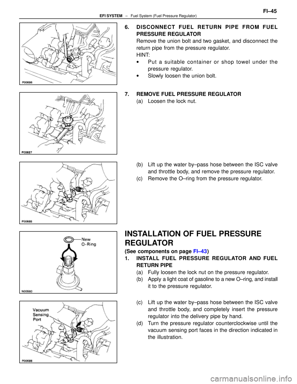
6. DISCONNECT FUEL RETURN PIPE FROM FUELPRESSURE REGULATOR
Remove the union bolt and two gasket, and disconnect the
return pipe from the pressure regulator.
HINT:
wPut a suitable container or shop towel under the
pressure regulator.
w Slowly loosen the union bolt.
7. REMOVE FUEL PRESSURE REGULATOR (a) Loosen the lock nut.
(b) Lift up the water by±pass hose between the ISC valveand throttle body, and remove the pressure regulator.
(c) Remove the O±ring from the pressure regulator.
INSTALLATION OF FUEL PRESSURE
REGULATOR
(See components on page FI±43)
1. INSTALL FUEL PRESSURE REGULATOR AND FUEL RETURN PIPE
(a) Fully loosen the lock nut on the pressure regulator.
(b) Apply a light coat of gasoline to a new O±ring, and install
it to the pressure regulator.
(c) Lift up the water by±pass hose between the ISC valve and throttle body, and completely insert the pressure
regulator into the delivery pipe by hand.
(d) Turn the pressure regulator counterclockwise until the vacuum sensing port faces in the direction indicated in
the illustration. FI±45
EFI SYSTEM
± Fuel System (Fuel Pressure Regulator)
WhereEverybodyKnowsYourName
Page 2104 of 4087
wAlign the spline of the ignition coil with the spline of
the holder, and slide on the holder.
NOTICE: Check that holder is correctly installed to the
grommet and ignition coil as shown in the illustration. w Check that the lock claw of the holder is engaged
by lightly pulling the holder.
5. INSTALL RH NO.3 TIMING BELT COVER (a) Install the three gaskets to the timing belt cover.
(b) Fit portion A of the timing belt cover, matching it with the
lower high±tension cord cover.
(c) Install the timing belt cover with the three bolts.
±
IGNITION SYSTEM High±Tension Cords and Cord ClampsIG±17
WhereEverybodyKnowsYourName
Page 2116 of 4087

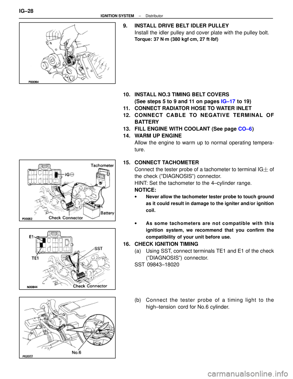
9. INSTALL DRIVE BELT IDLER PULLEYInstall the idler pulley and cover plate with the pulley bolt.
Torque: 37 N Vm (380 kgf Vcm, 27 ft Vlbf)
10. INSTALL NO.3 TIMING BELT COVERS
(See steps 5 to 9 and 11 on pages IG±17 to 19)
11. CONNECT RADIATOR HOSE TO WATER INLET
12. C O N N E C T C A B L E TO N E G AT I V E T E R M I N A L O F BATTERY
13. FILL ENGINE WITH COOLANT (See page CO±6)
14. WARM UP ENGINE Allow the engine to warm up to normal operating tempera-
ture.
15. CONNECT TACHOMETER Connect the tester probe of a tachometer to terminal IG � of
the check (ºDIAGNOSISº) connector.
HINT: Set the tachometer to the 4±cylinder range.
NOTICE:
w Never allow the tachometer tester probe to touch ground
as it could result in damage to the igniter and/or ignition
coil.
w As some tachometers are not compatible with this
ignition system, we recommend that you confirm the
compatibility of your unit before use.
16. CHECK IGNITION TIMING
(a) Using SST, connect terminals TE1 and E1 of the check(ºDIAGNOSISº) connector.
SST 09843±18020
(b) C onnect the tester probe of a timing light to the
high±tension cord for No.6 cylinder.
IG±28
±
IGNITION SYSTEM Distributor
WhereEverybodyKnowsYourName
Page 2117 of 4087
(c) Check the ignition timing.
Ignition timing: 8±125 BTDC @ idle
(Transmission in neutral range)
If the ignition timing is not as specified, check that following
conditions are normal: w Throttle valve fully closed
w Continuity between terminals IDL1 and E2 of the
throttle position sensor (See page FI±73)
w Valve timing (See page EM±51)
(e) Remove the SST from the check connector.
SST 09843±18020
17. DISCONNECT TACHOMETER AND TIMING LIGHT FROM ENGINE
18. INSTALL UPPER HIGH±TENSION CORD COVER (See step 10 on pages IG±18 and 19)
±
IGNITION SYSTEM DistributorIG±29
WhereEverybodyKnowsYourName
Page 2128 of 4087
(d) Lightly screw the oil filter into place, and tighten it untilthe gasket contacts the seat.
(e) Using SST, tighten it an additional 3/4 turn.
SST 09228±07500
3. FILL WITH ENGINE OIL (a) Clean and install the oil drain plug with a new gasket.
Torque: 45 N Vm (450 kgf Vcm, 33 ft Vlbf)
(b) Fill with fresh engine oil.
Oil grade: See page LU±5
Capacity:
Drain and refill w/ Oil filter change
4.8 liters (5.1 US qts, 4.2 lmp. qts)
w/o Oil filter change
4.5 liters (4.8 US qts, 4.0 lmp. qts)
Dry fill 5.2 liters (5.5 US qts, 4.6 lmp. qts)
(c) Reinstall the oil filler cap.
4. START ENGINE AND CHECK FOR LEAKS
5. RECHECK ENGINE OIL LEVEL (See page LU±5)
LU±8
±
LUBRICATION SYSTEM Replacement of Engine Oil and Oil Filter
WhereEverybodyKnowsYourName