Page 1639 of 4087
24. CONNECT IGNITER CONNECTOR(a) Connect the two igniter connectors.
(b) Install the wire clamp.
25. INSTALL RADIATOR (a) Install the two lower radiator supports to the radiator.
(b) Place the radiator on the body bracket.
(c) Slightly lift the radiator, and connect the two cooler hose(for cooling fan) to the hose clamp on the radiator fan
shrould.
(d) Install the upper radiator support with the two bolts and screw. Install the two upper radiator supports.
(e) Connect the following hoses: (1) Pressure hose to hydraulic pump
(2) Suction hose to hydraulic pump
EM±174
±
ENGINE MECHANICAL Cylinder Block
WhereEverybodyKnowsYourName
Page 1647 of 4087

The 1 UZ±FE engine has 8±cylinders in a V±arrangement at a bank an\
gle of 905. From the front of the RH
bank cylinders are numbered 2±4±6±8, and from the front of the LH b\
ank cylinders are numbered 1 ±3±5±7.
The crankshaft is supported by 5 bearings specified by the inside of the cr\
ankcase. These bearings are made
of a copper and lead alloy. The crankshaft is integrated with 8 weights which are cast along with it\
for balancing. Oil holes are built
into the center of the crankshaft for supplying oil to the connecting ro\
ds, pistons and other components. The ignition order is 1±8±4±3±6±5±7±2. The cylinder\
head is made of aluminum alloy, with a cross flow
type intake and exhaust layout and with pent±roof type combustion chambers. The spark plugs are loca\
ted in
the center of the combustion chambers.
At the front and rear of the intake manifold, a water passage has been p\
rovided which connects the RH
and LH cylinder heads. Exhaust and intake valves are equipped with irregular pitch springs made\
of special valve spring carbon
steel which are capable of following no matter what the engine speed.
The RH and LH intake camshafts are driven by a single timing belt, and a ge\
ar on the intake camshaft en-
gages with a gear on the exhaust camshaft to drive it. The camshaft jour\
nal is supported at 5 (intake) or 4 (ex-
haust) places between the valve lifters of each cylinder and on the front end of the cylinder \
head. Lubrication
of the cam journal gear is accomplished by oil being supplied through the \
oiler port in the center of the camshaft. Adjustment of the valve clearance is done by means of an outer shim type\
system, in which valve adjusting
shims are located above the valve lifters. This permits replacement of the sh\
ims without removal of the cam-
shafts. Pistons are made of high temperature±resistant aluminum alloy, and a depression is built into the piston
head to prevent interference with valves.
Piston pins are the full±floating type, with the pins fastened to neither the piston boss nor the connecting
rods. Instead, snap rings are fitted on both ends of the pins, preventing the\
pins from falling out. The No.1 compression ring is made of steel and the No.2 compression ring\
is made of cast iron. The oil
ring is m ade of a combination of steel and stainless steel. The outer diameter of\
each piston ring is slightly larger
than the diameter of the piston and the flexibility of the rings allows them\
to hug the cylinder walls when they
are mounted on the piston. Compression rings No.1 and No.2 work to prevent \
the leakage of gas from the cylin-
der and the oil ring works to scrape oil off the cylinder walls to prevent it from entering the combustion chamber. The cylinder block is made of aluminum alloy with a bank angle of 90 5. Cast iron cylinders are installed
inside the cylinder block. It has 8 cylinders which are approximately twice the length of th\
e piston stroke. The
top of each cylinder is closed off by the cylinder heads and the lower end of the cylinders becomes the crank-
case, in which the crankshaft is installed. In addition, the cylinder bl\
ock contains a water jacket, through which
coolant is pumped to cool the cylinders. The No.1 and No.2 oil pans are bolted onto the bottom of the cylinder block\
. The No.1 oil pan is made of
aluminum alloy. The No.2 oil pan is an oil reservoir made of pressed steel sheet. An o\
il level sensor is installed
in the No.1 oil pan (If the oil level drops below a set level, a warnin\
g light lights up.). A oil pan baffle plate keeps
sufficient oil in the bottom of the No.2 oil pan even when the vehicle is tilted. \
This dividing plate also prevents
the oil from making waves when the vehicle is stopped suddenly and the oil \
shifts away from the oil pump suction
pipe. Plastic region tightening bolts are used for the cylinder head, main bearing ca\
p and connecting rod.
EM±4
±
ENGINE MECHANICAL Operation
WhereEverybodyKnowsYourName
Page 1714 of 4087
 Check that the timing marks of the camshaft timingpulleys and timing belt rear plates aligned.
If not, turn the crankshaft one revolution (360 5).
27. REMOVE TIMING BELT TENSIONER HINT:
w(Re±u")
(b) Check that the timing marks of the camshaft timingpulleys and timing belt rear plates aligned.
If not, turn the crankshaft one revolution (360 5).
27. REMOVE TIMING BELT TENSIONER HINT:
w(Re±using timing belt)
If the installation marks have disappeared, before re-
moving the timing belt, place new installation marks on
the timing belt to match the timing marks of the camshaft
timing pulleys, and place a new installation mark on the
timing belt to match the end of the hydraulic pump.
w (When replacing timing belt tensioner only)
To avoid meshing of the timing pulley and timing belt, se-
cure one of them with string. And place matchmarks on
the timing belt and RH camshaft timing pulley.
Alternately loosen the two bolts, and remove them, the ten-
sioner and dust boot.
28. DISCONNECT TIMING BELT FROM CAMSHAFT TIMING PULLEYS
(a) Using SST, loosen the tension between the LH and RHcamshaft timing pulleys by slightly turning the LH
camshaft timing pulley clockwise.
SST 09278±54012
±
ENGINE MECHANICAL Timing BeltEM±41
WhereEverybodyKnowsYourName
Page 1722 of 4087
 Align the knock pin on the camshaft with the knock pingroove of the timing pulley.
(b) Slide the timing pulley, facing the ºLº mark forward.
(c) Using S")
11. INSTALL LH CAMSHAFT TIMING PULLEY(a) Align the knock pin on the camshaft with the knock pingroove of the timing pulley.
(b) Slide the timing pulley, facing the ºLº mark forward.
(c) Using SST, install and torque the pulley bolt.
SST 09278±54012
Torque: 108 N Vm (1,100 kgf Vcm, 80 ft Vlbf)
12. SET NO.1 CYLINDER TO TDC/COMPRESSION
(a) (Crankshaft Pulley Position)Turn the crankshaft pulley, and align its groove with the
ºOº timing mark of the No.1 timing belt cover.
(b) (Camshaft Timing Pulley Position) Using SST, t urn the camshaft timing pulley, and align the
timing marks of the camshaft timing pulley and timing
belt rear plate.
SST 09278±54012
13. INS TALL TIMING BE LT TO LH CAMS HAFT TIMING PULLEY
(a) Align the installation mark on the timing belt with the end
of the hydraulic pump.
(b) Remove any oil or water on the LH camshaft timing pulley, and keep it clean.
(c) Using SST, slightly turn the LH camshaft timing pulley
clockwise. Align the installation mark on the timing belt
with the timing mark of the camshaft timing pulley, and
hang the timing belt on the LH camshaft timing pulley.
SST 09278±54012
±
ENGINE MECHANICAL Timing BeltEM±49
WhereEverybodyKnowsYourName
Page 1723 of 4087
 Using SST, align the timing marks of the LH camshaftpulley and timing belt rear plate.
SST 09278±54012
(e) Check that the timing belt has tension between the crankshaft timing pulley and LH c")
(d) Using SST, align the timing marks of the LH camshaftpulley and timing belt rear plate.
SST 09278±54012
(e) Check that the timing belt has tension between the crankshaft timing pulley and LH camshaft timing pulley.
14. INSTALL TIMING BELT TO RH CAMSHAFT TIMING PULLEY
(a) Remove any oil or water on the RH camshaft timing andwater pump pulley, and keep them clean.
(b) Using SST, slightly turn the RH camshaft timing pulley clockwise. Align the installation mark on the timing belt
with the timing mark of the camshaft timing pulley, and
hang the timing belt on the RH camshaft timing pulley.
SST 09278±54012
(c) Using SST, align the timing marks of the RH camshaft pulley and timing belt rear plate.
SST 09278±54012
(d) Check that the timing belt has tension between the RH
camshaft timing pulley and LH camshaft pulley.
15. SET TIMING BELT TENSIONER (a) Using a press, slowly press in the push rod using981±9,807 N (100±1,000 kgf, 220±2,205 lbf) of
pressure.
(b) Align the holes of the push rod and housing, pass a 1.27
mm hexagon wrench through the holes to keep the
setting position of the push rod.
(c) Release the press.
(d) Install the dust boot to the tensioner.
EM±50
±
ENGINE MECHANICAL Timing Belt
WhereEverybodyKnowsYourName
Page 1744 of 4087
 Using a 45 � carbide cutter, resurface the valve seats.
Remove only enough metal to clean the seats.
(b) Check the valve seating position.
Apply a thin coat of")
8. INSPECT AND CLEAN VALVE SEATS(a) Using a 45 � carbide cutter, resurface the valve seats.
Remove only enough metal to clean the seats.
(b) Check the valve seating position.
Apply a thin coat of prussian blue (or white lead) to the valve
face. Lightly press the valve against the seat. Do not rotate
the valve.
(c) Check the valve face and seat for the following: w If blue appears 360 � around the face, the valve is
concentric. If not, replace the valve.
w If blue appears 360 � around the valve seat, the
guide and face are concentric. If not, resurface the
seat.
w Check that the seat contact is in the middle of the
valve face with the following width:
Intake 1.0±1.4 mm (0.039±0.055 in.)
Exhaust 1.2±1.6 mm (0.047±0.063 in.)
If not, correct the valve seats as follows:
(1) If the seating is too high on the valve face, use 15 5
and 45 5 cutters to correct the seat.
(2) If the seating is too low on the valve face, use 75 5
and 45 5 cutters to correct the seat.
±
ENGINE MECHANICAL Cylinder HeadEM±47
WhereEverybodyKnowsYourName
Page 1751 of 4087
 Using a plastic±faced hammer, lightly tap the valve stem
tip to assure proper fit.
4. INSTALL VALVE LIFTERS AND SHIMS (a) Install the valve lifter and shim.
(b) Check that the valve lifter r")
(d) Using a plastic±faced hammer, lightly tap the valve stem
tip to assure proper fit.
4. INSTALL VALVE LIFTERS AND SHIMS (a) Install the valve lifter and shim.
(b) Check that the valve lifter rotates smoothly by hand.
INSTALLATION OF CYLINDER HEAD
(See Components on pages EM±34 and 35)1. INSTALL CYLINDER HEAD
A. Place cylinder head on cylinder block (a) Place a new cylinder head gasket in position on thecylinder block.
NOTICE: Be sure to install it correctly.
(b) Place the cylinder head in position on the cylinder head
gasket and connect the heater water hose to the union.
B. Install cylinder head bolts
HINT:
wThe cylinder head bolts are tightened in two progressive
steps (steps (c) and (f)).
w If any of bolts break or deform, replace them.
(a) Apply a light coat of engine oil on the threads and under
the heads of the cylinder head bolts.
(b) Install the 14 plate washers to each cylinder head bolt.
(c) First, using a 10 mm bi±hexagon wrench, uniformly tighten the cylinder head bolts in several passes in the
sequence shown.
Torque: 34 N Vm (350 kgf Vcm, 25 ft Vlbf)
If any one of the bolts does not meet the torque specification,
replace the bolt.
EM±54
±
ENGINE MECHANICAL Cylinder Head
WhereEverybodyKnowsYourName
Page 1752 of 4087
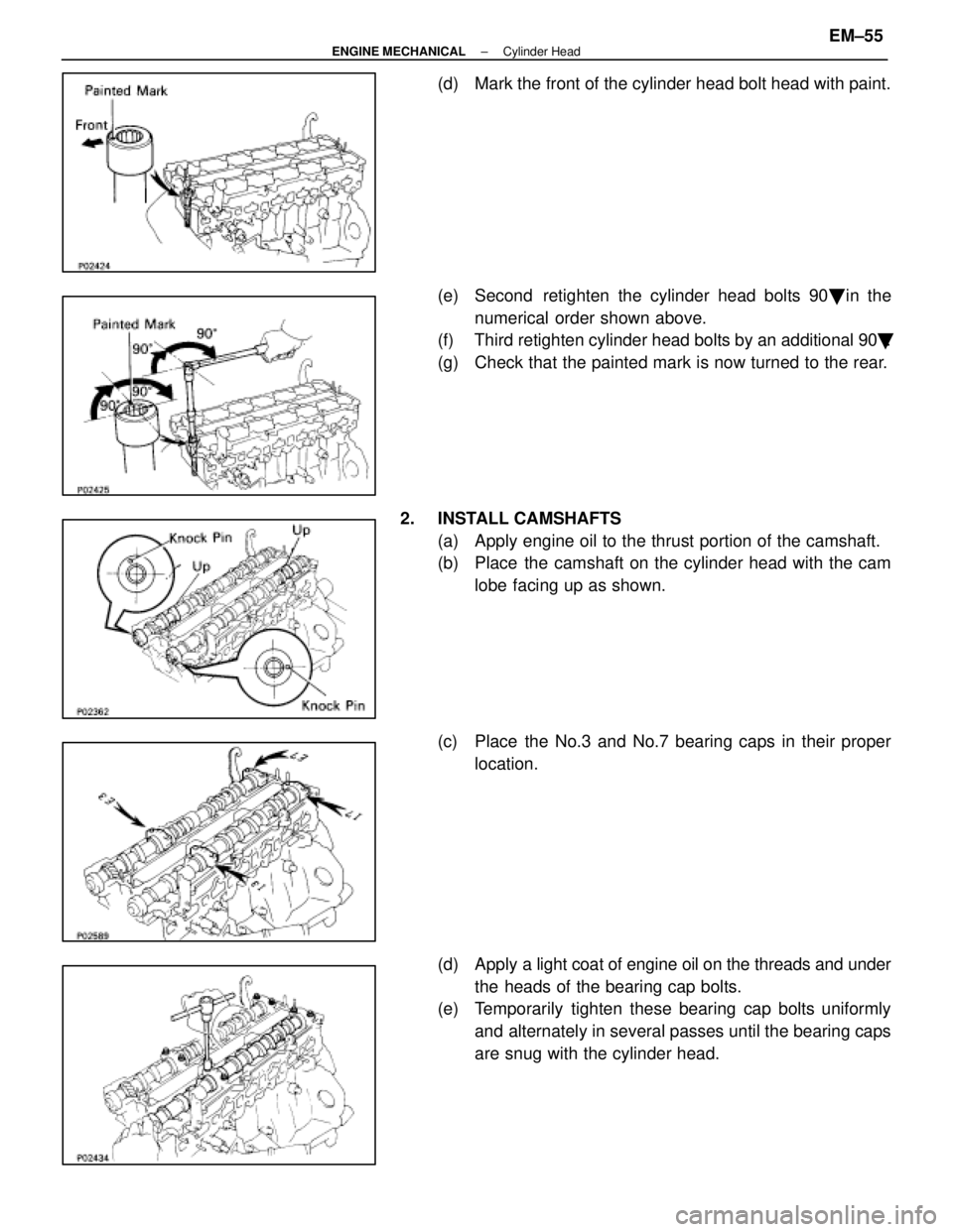
(d) Mark the front of the cylinder head bolt head with paint.
(e) Second retighten the cylinder head bolts 90� in the
numerical order shown above.
(f) Third retighten cylinder head bolts by an additional 90 �.
(g) Check that the painted mark is now turned to the rear.
2. INSTALL CAMSHAFTS (a) Apply engine oil to the thrust portion of the camshaft.
(b) Place the camshaft on the cylinder head with the camlobe facing up as shown.
(c) Place the No.3 and No.7 bearing caps in their proper location.
(d) Apply a light coat of engine oil on the threads and under
the heads of the bearing cap bolts.
(e) Temporarily tighten these bearing cap bolts uniformly
and alternately in several passes until the bearing caps
are snug with the cylinder head.
±
ENGINE MECHANICAL Cylinder HeadEM±55
WhereEverybodyKnowsYourName
 Connect the two igniter connectors.
(b) Install the wire clamp.
25. INSTALL RADIATOR (a) Install the two lower radiator supports to the radiator.
(b) Place the r")