Page 1800 of 4087
 Install the other bearing caps in the sequence shownwith the arrow mark facing forward.
HINT: Align the arrow marks at front and rear of the cylinder
head with the mark on the bearing cap.
(g) A")
(f) Install the other bearing caps in the sequence shownwith the arrow mark facing forward.
HINT: Align the arrow marks at front and rear of the cylinder
head with the mark on the bearing cap.
(g) Apply a light coat of engine oil on the threads and under
the heads (A only) of the bearing cap bolts.
HINT: Do not apply engine oil under the heads of the bearing
cap bolts (B).
(h) Install a new seal washer to the bearing cap bolt (B).
Install the eight bearing cap bolts as shown.
HINT:
w Use bearing cap bolts 38 mm (1.50 in.) in length. The
bolts are black (A) or silver (B) in color. Install the two
silver bolts to the front bearing cap. Install the six black
bolts to the other positions.
w After installing the oil feed pipe, install the two bolts to
the bearing cap second from the front as directed in step
D (i).
(i) Uniformly tighten the eight bearing cap bolts in several passes in the sequence shown.
Torque: 16 N Vm (160 kgf Vcm, 12 ft Vlbf)
D. Install exhaust camshaft to LH cylinder head
(a) Set the timing mark (two dot marks) of the camshaftdrive gear at 15 ° angle by turning the hexagon wrench
head portion of the intake camshaft with a wrench.
(b) Apply MP grease to the thrust portion of the exhaust camshaft.
(c) Align the timing marks (two dot marks) of the camshaft
drive and driven gears.
(d) Place the exhaust camshaft on the cylinder head.
±
ENGINE MECHANICAL Cylinder HeadsEM±99
WhereEverybodyKnowsYourName
Page 1801 of 4087
 Check that the exhaust camshaft moves smoothly in the
thrust direction.
(f) Install the front bearing cap with the arrow mark facing forward.
HINT:
w Installing the front bearing cap will determ")
(e) Check that the exhaust camshaft moves smoothly in the
thrust direction.
(f) Install the front bearing cap with the arrow mark facing forward.
HINT:
w Installing the front bearing cap will determine the thrust
position of the camshaft.
w Align the arrow marks at front and rear of the cylinder
head with the mark on the bearing cap.
(g) Install the other bearing caps in the sequence shown with the arrow mark facing forward.
HINT: Align the arrow marks at front and rear of the cylinder
head with the mark on the bearing cap.
(h) Apply a light coat of engine oil on the threads and under
the heads of the bearing cap bolts.
(i) Install the oil feed pipe and ten bolts.
HINT: Use bearing cap bolts 38 mm (1.50 in.) and 52 mm
(2.05 in.) in length. Use black colored 38 mm (1.50 in.) bolts.
Install the two 52 mm (2.05 in.) bolts in outside positions of
the oil pipe. Install the eight 38 mm (1.50 in.) bolts in the other
positions.
(j) Uniformly tighten the eight bearing cap bolts on the
bearing caps of the exhaust camshaft in several passes
in the sequence shown.
Torque: 16 N Vm (160 kgf Vcm, 12 ft Vlbf)
EM±100±
ENGINE MECHANICAL Cylinder Heads
WhereEverybodyKnowsYourName
Page 1804 of 4087
12. INSTALL ENGINE HANGERSInstall the engine hanger with the two bolts.
Install the two engine hangers.
Torque: 37 N Vm (380 kgf Vcm, 27 ft Vlbf)
13. CONNECT GROUND STRAP TO RH CYLINDER HEAD
14. INSTALL ENGINE WIRE TO RH CYLINDER HEAD
Install the engine wire with the two bolts.
15. INSTALL ENGINE WIRE TO LH CYLINDER HEAD Install the engine wire with the five bolts.
16. INSTALL EGR PIPE TO RH EXHAUST MANIFOLD Install a new gasket and the EGR pipe with the two new nuts.
Torque: 18 N Vm (185 kgf Vcm, 13 ft Vlbf)
17. INSTALL OIL DIPSTICK AND GUIDE FOR ENGINE
(a) Install a new O±ring to the dipstick guide.
(b) Apply a light of engine oil on the O±ring.
(c) Push in the dipstick guide into the guide hole of the No.1
oil pan.
(d) Install the dipstick guide with the bolt.
(e) Install the oil dipstick.
18. INSTALL OIL DIPSTICK AND GUIDE FOR A/T
±
ENGINE MECHANICAL Cylinder HeadsEM±103
WhereEverybodyKnowsYourName
Page 1841 of 4087
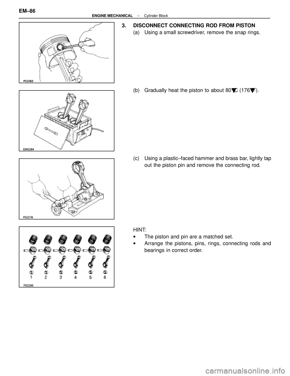
3. DISCONNECT CONNECTING ROD FROM PISTON(a) Using a small screwdriver, remove the snap rings.
(b) Gradually heat the piston to about 80 �C (176 �F).
(c) Using a plastic±faced hammer and brass bar, lightly tap out the piston pin and remove the connecting rod.
HINT:
w The piston and pin are a matched set.
w Arrange the pistons, pins, rings, connecting rods and
bearings in correct order.
EM±86
±
ENGINE MECHANICAL Cylinder Block
WhereEverybodyKnowsYourName
Page 1852 of 4087
3. PLACE CRANKSHAFT ON CYLINDER BLOCK
4. INSTALL MAIN BEARING CAP AND LOWER THRUSTWASHERS
A. Place main bearing cap and lower thrust washers on cyl- inder block
(a) Install the lower thrust washers on the No. 4 mainbearing with the grooves facing outward.
(b) Install the main bearing caps in numerical order with the arrows facing forward.
B. Install main bearing cap bolts HINT:
wThe main bearing cap bolts are tightened in two
progressive steps (steps (b) and (d)).
w If any of the main bearing bolts break or deform, replace
them.
(a) Apply a light coat of engine oil on the threads and under
the heads of the main bearing cap bolts.
(b) First, install and uniformly tighten the 14 main bearing
cap bolts in several passes in the sequence shown.
Torque: 44 N Vm (450 kgf Vcm, 33 ft Vlbf)
If any one of the main bearing cap bolts does not meet the
torque specification, replace the main bearing cap bolt.
±
ENGINE MECHANICAL Cylinder BlockEM±97
WhereEverybodyKnowsYourName
Page 1854 of 4087
 Apply a light coat of engine oil on the threads and under
the heads of the connecting rod cap bolts.
(b) At first, install and alternately tighten the bolts of the connecting rod cap in several")
(a) Apply a light coat of engine oil on the threads and under
the heads of the connecting rod cap bolts.
(b) At first, install and alternately tighten the bolts of the connecting rod cap in several passes.
Torque: 29 N Vm (300 kgf Vcm, 22 ft Vlbf)
If any one of the connecting rod cap bolts does not meet the
torque specification, replace the cap bolt.
(c) Mark the front of the connecting rod cap bolt with paint.
(d) Retighten the connecting rod cap bolts 905 in the
numerical order shown.
(e) Check that the painted mark is now at a 905 angle to the
front.
(f) Check that the crankshaft turns smoothly.
(g) Check the connecting rod thrust clearance. (See step 2 on page EM±77)
7. INSTALL REAR OIL SEAL RETAINER (a) Remove any old packing (FIPG) material and be carefulnot to drop any oil on the contact surfaces of the retainer
and cylinder block.
w Using a razor blade and gasket scraper, remove all the
old packing (FIPG) material from the gasket surfaces
and sealing groove.
w Thoroughly clean all components to remove all debris.
w Using a non±residue solvent, clean both sealing
surfaces.
(b) Apply seal packing to the retainer as shown in the illustration.
Seal packing: Part No. 08826±00080 or equivalent
w Install a nozzle that has been cut to a 2±3 mm
(0.08±0.12 in.) opening.
w Parts must be assembled within 3 minutes of
application. Otherwise the material must be removed
and reapplied.
w Immediately remove nozzle from the tube and reinstall
cap.
±
ENGINE MECHANICAL Cylinder BlockEM±99
WhereEverybodyKnowsYourName
Page 1881 of 4087
 Reinstall the fuel pressure regulator to the RH deliverypipe.
w Fully loosen the lock nut on the pressure regulator.
w Apply a light coat of gasoline to a new O±ring, and
install it to the pres")
(e) Reinstall the fuel pressure regulator to the RH deliverypipe.
w Fully loosen the lock nut on the pressure regulator.
w Apply a light coat of gasoline to a new O±ring, and
install it to the pressure regulator.
w Completely insert the pressure regulator into the
delivery pipe by hand.
w Turn the pressure regulator counterclockwise until
the vacuum sensing port faces in the direction
indicated in the illustration.
INSTALLATION OF INJECTORS
(See Components on page FI±49)
1. INSTALL INJECTORS AND DELIVERY PIPE (a) Install the grommet to each injector.
(b) Apply a light coat of gasoline to a new O±ring and install
it to each injector.
(c) W h i l e t u r n i n g t h e i n j e c t o r c l o c k w i s e a n d counterclockwise, push it to the delivery pipes. Install
the eight injectors.
(d) Position the injector connector outward.
(e) Place the eight insulators and four spacers in position on the intake manifold.
FI±54
EFI SYSTEM
± Fuel System (Injectors)
WhereEverybodyKnowsYourName
Page 1983 of 4087

Engine & ECT ECU
TERMINALS OF ENGINE & ECT ECU
TerminalNo.SymbolConnectionTerminalNo.SymbolConnection
E9 ± 1IGSWIgnition SwitchE9 ± 31+ BEFI Main Relay
2SPDNo. 1 Speed Sensor32+ B1EFI Main Relay
3KDKick±Down Switch33BATTBattery
4STPStop light Switch34A/CA/C Control Assembly
5±35±
6WªCHECKº Engine Warning Light36±
7RNeutral Start Switch37TRTRAC ECU
8±38NEOTRAC ECU
92Neutral Start Switch39VTO2TRAC ECU
10LNeutral Start Switch40VTO1TRAC ECU
11ADCC ECUE10 ± 1NCO �T/M Input Speed Sensor
12OD1CC ECU2±
13±3SP2�No. 2 Speed Sensor for ECT
14±4E11ECU Ground
15±5G2�Cam position Sensor
16±6G1�Cam position Sensor
17TTTDCL7NF�Engine Speed Sensor
18PECT Pattern Select Switch8±
19TE2Check Connector9S2ECT Solenoid Value
20TE1Check Connector10S1ECT Solenoid Value
21D1Fuel Pump ECU11±
22FPCFuel Pump ECU12±
23ACMGA/C Magnet Clutch Relay13SLN �No.3 ECT Solenoid Valve
24M±RELEFI Main Relay14SLU�No.4 ECT Solenoid Valve
25±15±
26±16±
27±17#10No.3 and No.5 Injectors
28OD2O/D Main Relay18#20No.4 and No.6 Injectors
29±19#20No.2 and No.8 Injectors
30±20#40No.1 and No.7 Injectors
Engine & ECT ECU Terminals
FI±126 ± Electronic Control \
System (Engine & ECT ECU)EFI SYSTEM
WhereEverybodyKnowsYourName

13. CONNECT GROUND STRAP TO RH CYLINDER HEAD
14. I")
 Install the lower thrust washe")