Page 1557 of 4087

(a) Apply a light coat of engine oil on the threads and under themain bearing cap nuts.
(b) Install and uniformly tighten the 20 main bearing cap nuts in
several passes, in the sequence shown.
Torque: 27 N Vm (275 kgf Vcm, 20 ft Vlbf)
If any one of the main bearing cap nuts does not meet the
torque specification, replace the main bearing cap stud bolt.
(c) Mark the front of the main bearing cap nut with paint.
(d) Retighten the main bearing cap bolts 90 � in the numerical
order shown.
(e) Check that the painted mark is now at a 90 � angle to the front.
C. Install main bearing cap bolts
(a) Install a new seal washer to the main bearing cap bolt.
(b) Install and uniformly tighten the 10 main bearing cap bolts.
Torque: 49 N Vm (500 kgf Vcm, 36 ft Vlbf)
(c) Check that the crankshaft turns smoothly.
5. CHECK CRANKSHAFT THRUST CLEARANCE
Using a dial indi cator, measure the thrust clearance while pry-
ing the crankshaft back and forth with a screwdriver.
Standard thrust clearance:
0.020 ± 0.220 mm (0.0008 ± 0.0087 in.)
Maximum thrust clearance: 0.30 mm (0.0118 in.)
If the thrust clearance is greater than maximum, replace the
thrust washers as a set.
Thrust washer thickness:2.440 ± 2.490 mm (0.0961 ± 0.0980 in.)
±
1UZ±FE ENGINE ENGINE MECHANICALEG±181
WhereEverybodyKnowsYourName
Page 1559 of 4087

B. Install connecting rod cap boltsHINT:
wThe connecting rod cap bolts are tightened in 2
progressive steps (steps (b) and (d)).
w If any one of the connecting rod cap bolts is broken or
deformed, replace it.
(a) Apply a light coat of engine oil on the threads and under the heads of the connecting rod cap bolts.
(b) Install and alternately tighten the 2 connecting rod cap bolts
in several passes.
Torque: 25 N Vm (250 kgf Vcm, 18 ft Vlbf)
If any one of the connecting rod cap bolts does not meet the
torque specification, replace the connecting rod cap bolts.
(c) Mark the front of the connecting cap bolt with paint.
(d) Retighten the cap nuts 90 � as shown.
(e) Check that the painted mark is now at a 90 � angle to the front.
(f) Check that the crankshaft turns smoothly.
8. CHECK CONNECTING ROD OIL CLEARANCE
Using a dial indicator, measure the thrust clearance while
moving the connecting rod back and forth.
Standard thrust clearance:
0.160 ± 0.290 mm (0.0063 ± 0.0138 in.)
Maximum thrust clearance: 0.35 mm (0.0138 in.)
If the thrust clearance is greater than maximum, replace the
connecting rod assembly(s). If necessary, replace the crank-
shaft.
Connecting rod thickness:22.880 ± 22.920 mm (0.9008 ± 0.9024 in.)
±
1UZ±FE ENGINE ENGINE MECHANICALEG±183
WhereEverybodyKnowsYourName
Page 1575 of 4087
20. INSTALL POWER STEERING (PS) SOLENOID VALVECONNECTOR
21. CONNECT ENGINE WIRE CONNECTORS
22. CONNECT THEFT DETERRENT HORN CONNECTOR
23. INSTALL GROUND CABLE TO BODY
24. CONNECT IGNITER CONNECTORS
(a) Connect the 2 igniter connectors HINT: Connect the yellow taped connector to the igniter on
the rear side.
(b) Install the wire clamp.
25. INSTALL RADIATOR ASSEMBLY
(a) Install the 2 lower radiator supports to the radiator.
(b) Place the radiator assembly on the body bracket.
(c) Slightly lift the radiator, and connect the 2 oil cooler hoses (for
cooling fan) to the hose clamp on the radiator fan shroud.
±
1UZ±FE ENGINE ENGINE MECHANICALEG±199
WhereEverybodyKnowsYourName
Page 1586 of 4087
(3) Two oil cooler hoses (for A/T) from radiator Plug thehose ends.
(4) Suction hose from hydraulic pump
(5) Pressure hose from hydraulic pump
(c) Re mo ve th e two bo lts, scre w an d u pper radiator
support. Remove the two upper radiator supports.
(d) Slightly lift the radiator, and d isconnect the two oil cooler
hoses (for cooling fan) from the hose clamp on the
radiator fan shrould.
(e) Remove the radiator.
14. DISCONNECT IGNITER CONNECTORS (a) Disconnect the two igniter connectors.
(b) Disconnect the wire clamp from the body.
±
ENGINE MECHANICAL Cylinder BlockEM±121
WhereEverybodyKnowsYourName
Page 1609 of 4087

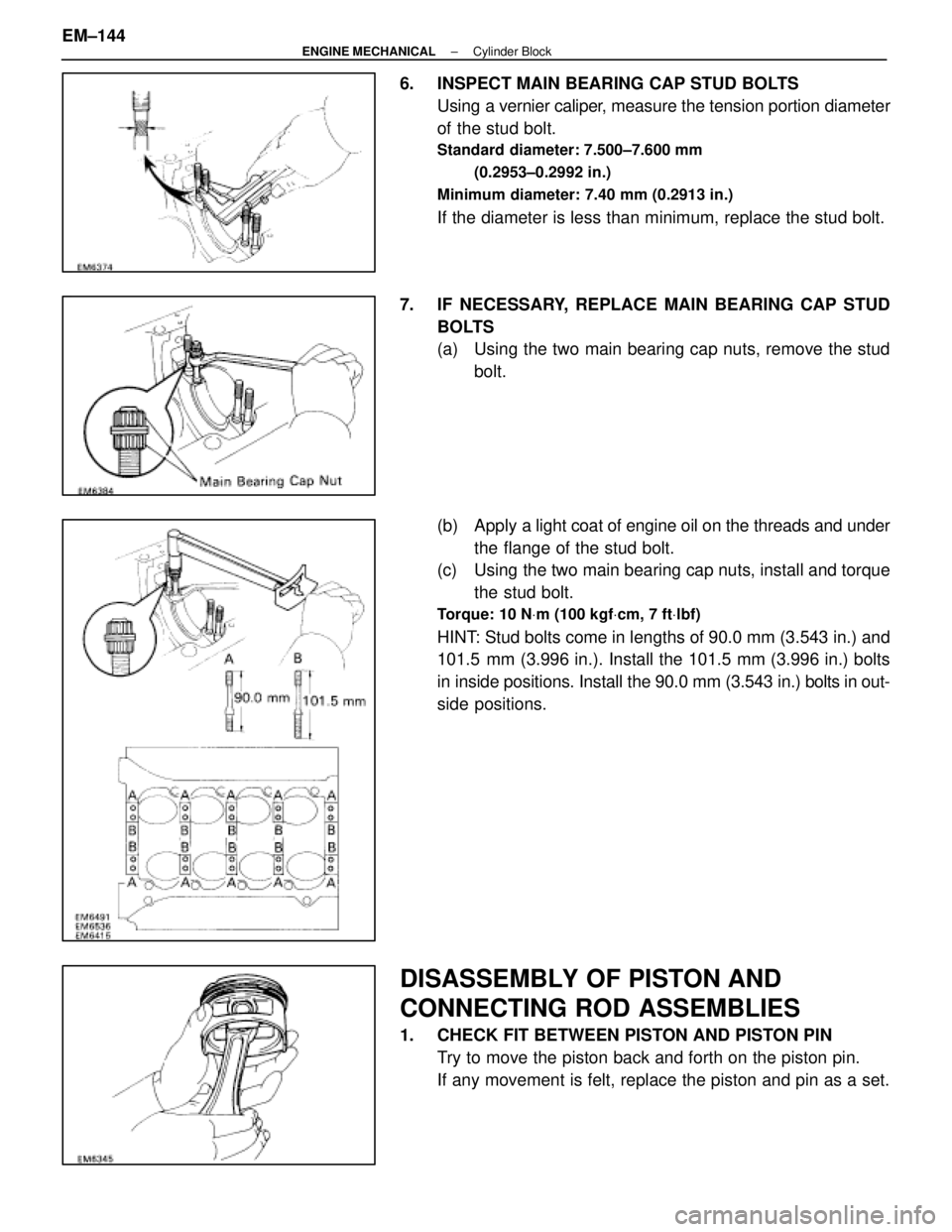
6. INSPECT MAIN BEARING CAP STUD BOLTSUsing a vernier caliper, measure the tension portion diameter
of the stud bolt.
Standard diameter: 7.500±7.600 mm
(0.2953±0.2992 in.)
Minimum diameter: 7.40 mm (0.2913 in.)
If the diameter is less than minimum, replace the stud bolt.
7. IF NECESSARY, REPLACE MAIN BEARING CAP STUD BOLTS
(a) Using the two main bearing cap nuts, remove the studbolt.
(b) Apply a light coat of engine oil on the threads and under
the flange of the stud bolt.
(c) Using the two main bearing cap nuts, install and torque
the stud bolt.
Torque: 10 N Vm (100 kgf Vcm, 7 ft Vlbf)
HINT: Stud bolts come in lengths of 90.0 mm (3.543 in.) and
101.5 mm (3.996 in.). Install the 101.5 mm (3.996 in.) bolts
in inside positions. Install the 90.0 mm (3.543 in.) bolts in out-
side positions.
DISASSEMBLY OF PISTON AND
CONNECTING ROD ASSEMBLIES
1. CHECK FIT BETWEEN PISTON AND PISTON PIN
Try to move the piston back and forth on the piston pin.
If any movement is felt, replace the piston and pin as a set.
EM±144
±
ENGINE MECHANICAL Cylinder Block
WhereEverybodyKnowsYourName
Page 1610 of 4087
2. REMOVE PISTON RINGS(a) U s i n g a p i s t o n r i n g e x pander, remove the two
compression rings.
(b) Remove the two side rails and oil ring expander by hand.
HINT: Arrange the piston rings in correct order only.
3. DISCONNECT CONNECTING ROD FROM PISTON (a) Using a small screwdriver, pry out the two snap rings.
(b) Gradually heat the piston to approx. 60 °C (140 °F).
(c) Using a plastic±face hammer and brass bar, lightly tap out the piston pin and remove the connecting rod.
±
ENGINE MECHANICAL Cylinder BlockEM±145
WhereEverybodyKnowsYourName
Page 1622 of 4087

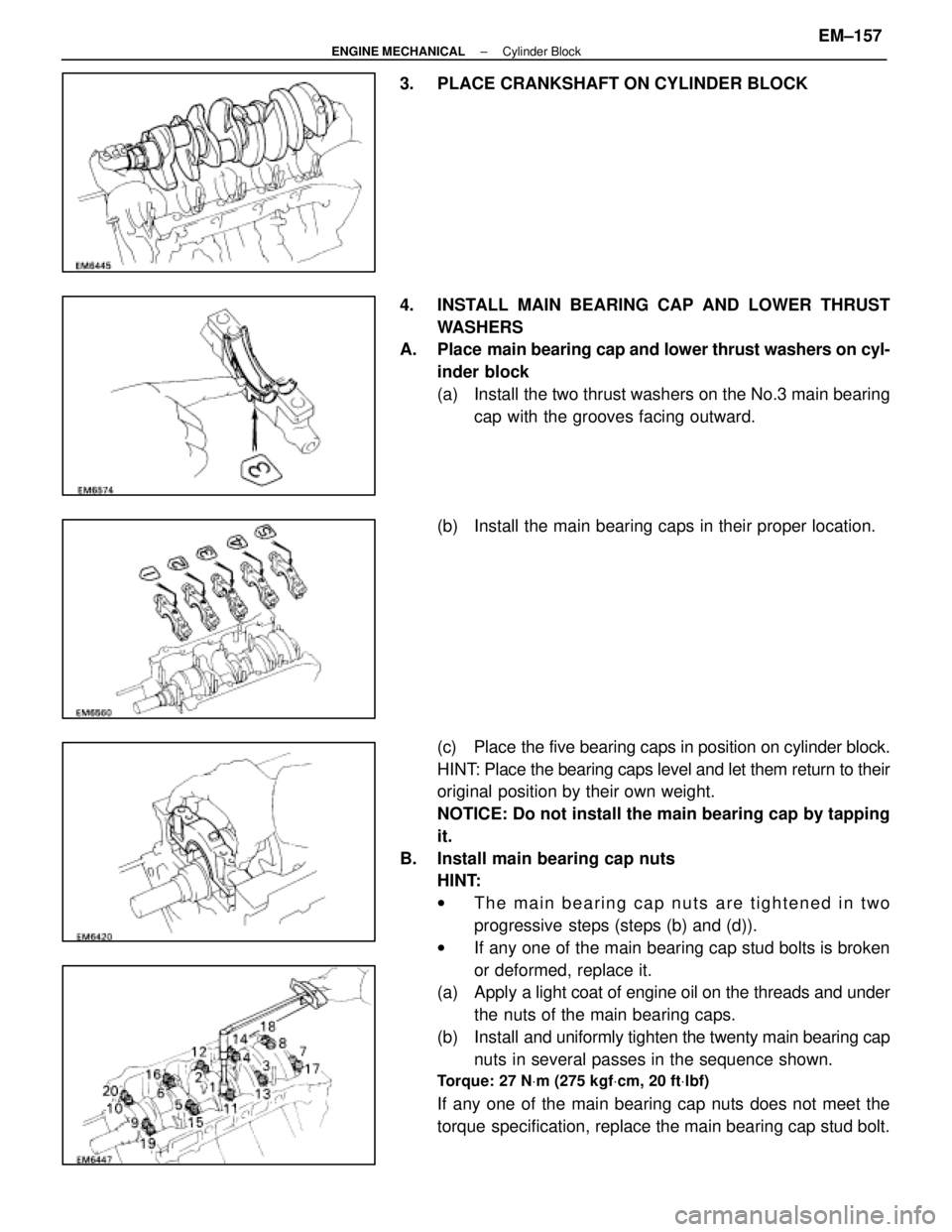
3. PLACE CRANKSHAFT ON CYLINDER BLOCK
4. INSTALL MAIN BEARING CAP AND LOWER THRUSTWASHERS
A. Place main bearing cap and lower thrust washers on cyl-
inder block
(a) Install the two thrust washers on the No.3 main bearing cap with the grooves facing outward.
(b) Install the main bearing caps in their proper location.
(c) Place the five bearing caps in position on cylinder block.
HINT: Place the bearing caps level and let them return to their
original position by their own weight.
NOTICE: Do not install the main bearing cap by tapping
it.
B. Install main bearing cap nuts HINT:
wThe main bearing cap nuts are tightened in two
progressive steps (steps (b) and (d)).
w If any one of the main bearing cap stud bolts is broken
or deformed, replace it.
(a) Apply a light coat of engine oil on the threads and under
the nuts of the main bearing caps.
(b) Install and uniformly tighten the twenty main bearing cap
nuts in several passes in the sequence shown.
Torque: 27 N Vm (275 kgf Vcm, 20 ft Vlbf)
If any one of the main bearing cap nuts does not meet the
torque specification, replace the main bearing cap stud bolt.
±
ENGINE MECHANICAL Cylinder BlockEM±157
WhereEverybodyKnowsYourName
Page 1624 of 4087

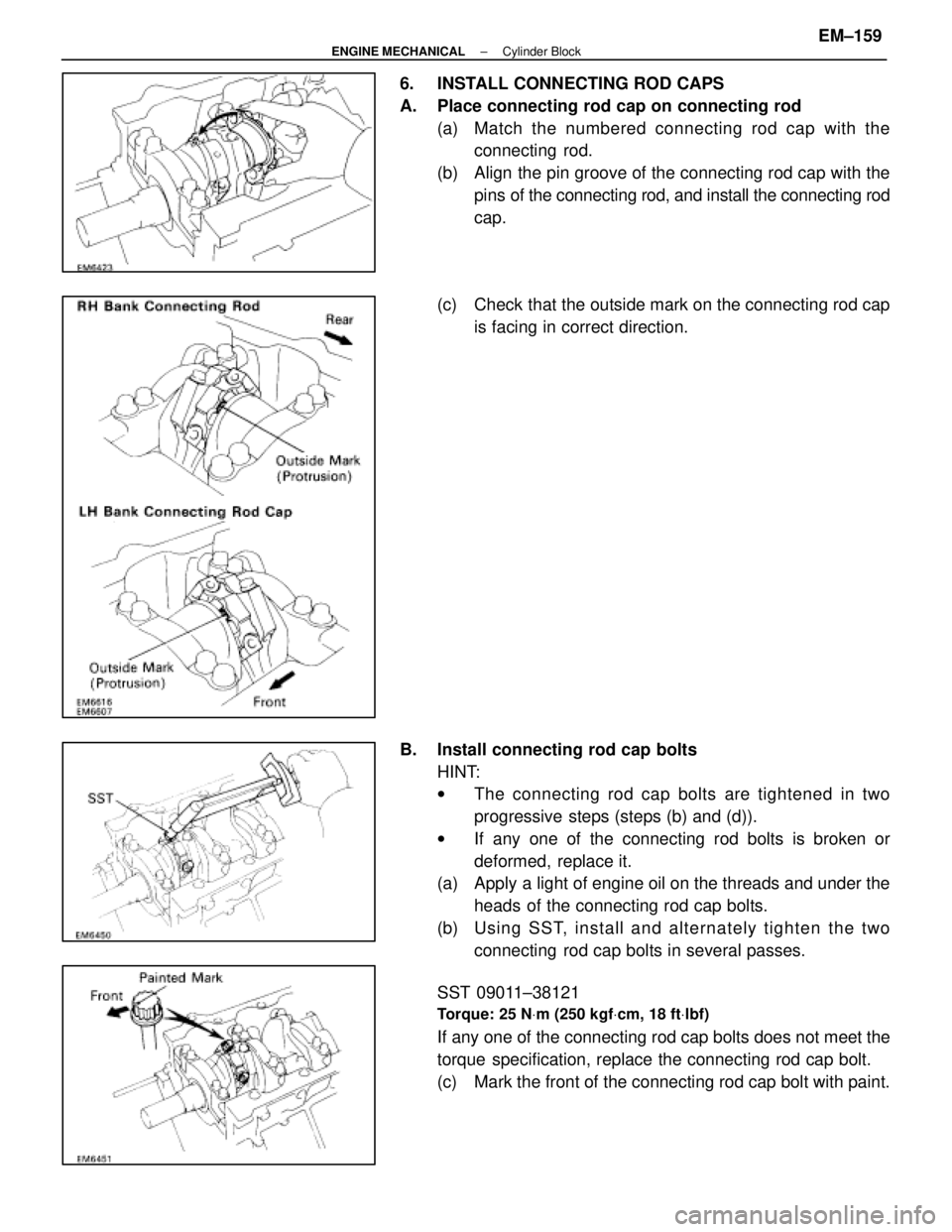
6. INSTALL CONNECTING ROD CAPS
A. Place connecting rod cap on connecting rod(a) Match the numbered c onnecting rod cap with the
connecting rod.
(b) Align the pin groove of the connecting rod cap with the pins of the connecting rod, and install the connecting rod
cap.
(c) Check that the outside mark on the connecting rod cap is facing in correct direction.
B. Install connecting rod cap bolts HINT:
wThe connecting rod cap bolts are tightened in two
progressive steps (steps (b) and (d)).
w If any one of the connecting rod bolts is broken or
deformed, replace it.
(a) Apply a light of engine oil on the threads and under the
heads of the connecting rod cap bolts.
(b) Usin g SS T, in sta ll an d alte rn a te ly tig h te n th e two connecting rod cap bolts in several passes.
SST 09011±38121
Torque: 25 N Vm (250 kgf Vcm, 18 ft Vlbf)
If any one of the connecting rod cap bolts does not meet the
torque specification, replace the connecting rod cap bolt.
(c) Mark the front of the connecting rod cap bolt with paint.
±
ENGINE MECHANICAL Cylinder BlockEM±159
WhereEverybodyKnowsYourName