Page 1206 of 4087
INSTALLATION
BrazeBraze
1. Temporarily install the new parts and check the
fit of the luggage compartment door and rear
combination light.
BODY PANEL REPLACEMENTRE-49
WhereEverybodyKnowsYourName
Page 1232 of 4087

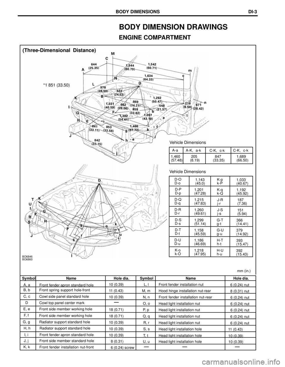
mm (in.)
BO6846
BO6860
1,218
(47.95)392
(15.43)
H-U
h-u
K-o
k-O 1,186
(46.69)
H-T
h-t
393
(15.47)
D-U
D-u 379
(14.92)
G-U
g-u
1,158
(45.59)
D-T
D-t G-T
g-t
366
(14.41)
1,299
(51.14)
D-S
D-s 151
(5.94)
1,260
(49.61)
D-R
D-r
J-S
j-s187
(7.36)
1,215
(47.83)
D-Q
D-q
J-R
j-r1,192
(45.92)
1,201
(47.28)
K-q
k-Q
D-P
D-p 1,033
(40.67)
1,143
(45.0)
K-p
k-P
D-O
D-o
Vehicle Dimensions
1,689
(66.50)
847
(33.35)
205
(8.19)
1,460
(57.48) C-K, c-k
C-K, c-k
A-K, a-k
A-a
Vehicle Dimensions
*1 851 (33.50)
(Three-Dimensional Distance)
Symbol Name Hole dia. Symbol Name Hole dia.
A, a Front fender apron standard hole 10 (0.39)
L, l Front fender installation nut
6 (0.24) nut
B, b Front spring support hole-front
11 (0.43)M, m Hood hinge installation nut-rear
8 (0.31) nut
C, c Cowl side panel standard hole
10 (0.39)N, n Front fender installation nut-rear
6 (0.24) nut
D Cowl top panel center mark
O, oHead light installation nut
6 (0.24) nut
E, e Front side member working hole
18 (0.71)P, pHead light installation nut
6 (0.24) nut
F, f Front side member working hole
18 (0.71)Q, qHead light installation nut
6 (0.24) nut
G, g Radiator support standard hole
10 (0.39)R, rHead light installation nut
6 (0.24) nut
H, h Radiator support standard hole
10 (0.39)S, sHead light installation hole
11 (0.43)
I, i Front fender apron standard hole 10 (0.39)T, t Head light installation hole 10 (0.39)
J, j Front side member standard hole
8 (0.31)U, u Head light installation hole 10 (0.39)
K, k Front fender installation nut-front
6 (0.24) screw
BODY DIMENSION DRAWINGS
ENGINE COMPARTMENT
BODY DIMENSIONSDI-3
WhereEverybodyKnowsYourName
Page 1243 of 4087

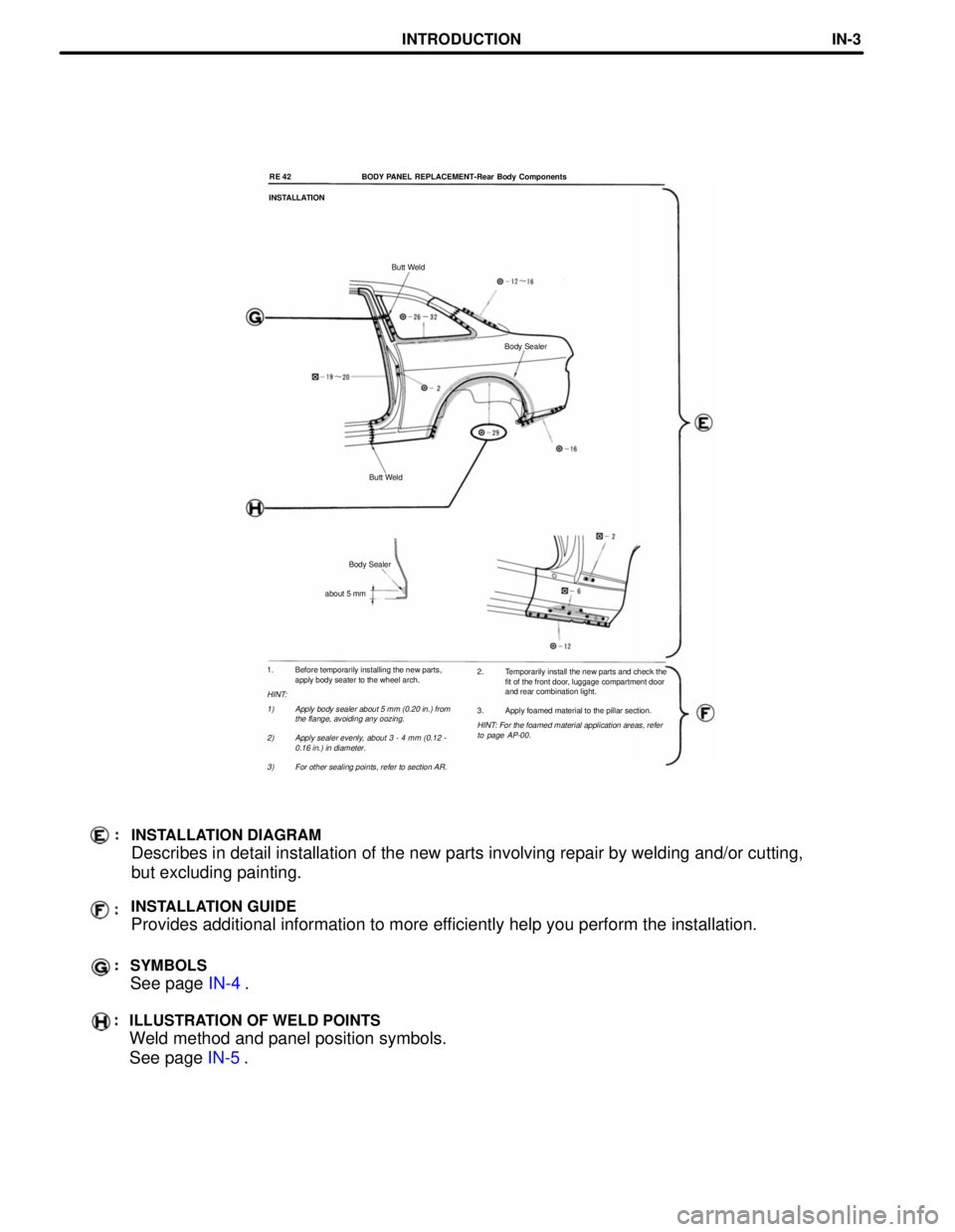
1. Before temporarily installing the new parts,apply body seater to the wheel arch.
HINT:
1) Apply body sealer about 5 mm (0.20 in.) from the flange, avoiding any oozing.
2) Apply sealer evenly, about 3 - 4 mm (0.12 - 0.16 in.) in diameter.
3) For other sealing points, refer to section AR.
RE 42 BODY PANEL REPLACEMENT-Rear Body Components
INSTALLATION
Butt Weld
Body Sealer
Butt Weld
Body Sealer
about 5 mm
2. Temporarily install the new parts and check thefit of the front door, luggage compartment door
and rear combination light.
3. Apply foamed material to the pillar section.
HINT: For the foamed material application areas, refer to page AP-00.
INSTALLATION DIAGRAM
Describes in detail installation of the new parts involving repair by we\
lding and/or cutting,
but excluding painting.
INSTALLATION GUIDE
Provides additional information to more efficiently help you perform the installation.
SYMBOLS
See page IN-4.
ILLUSTRATION OF WELD POINTS
Weld method and panel position symbols.
See page IN-5.
INTRODUCTIONIN-3
WhereEverybodyKnowsYourName
Page 1246 of 4087

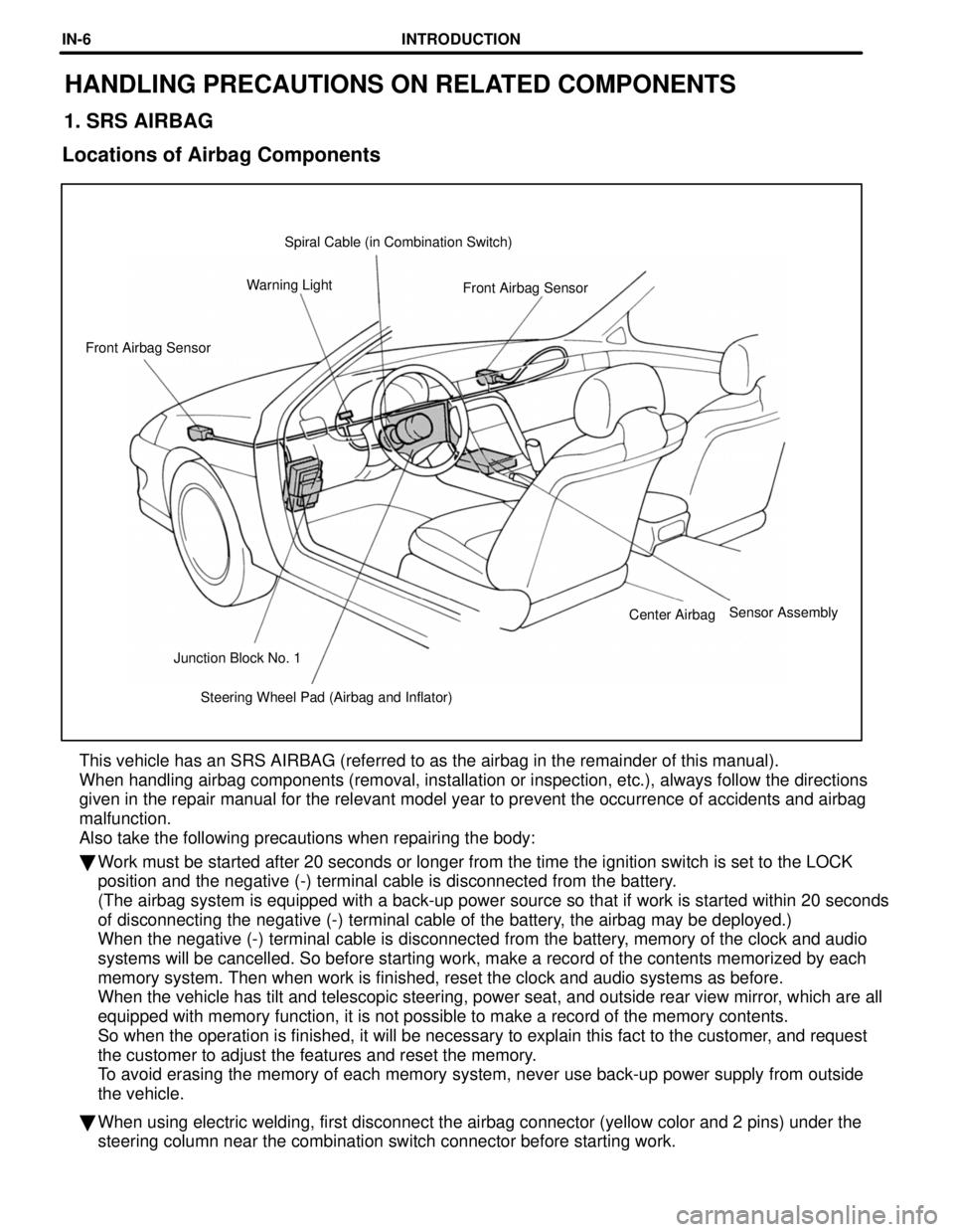
Steering Wheel Pad (Airbag and Inflator)
Junction Block No. 1 Center Airbag
Front Airbag Sensor
Front Airbag Sensor
Warning Light Spiral Cable (in Combination Switch)
HANDLING PRECAUTIONS ON RELATED COMPONENTS
1. SRS AIRBAG
Locations of Airbag Components
This vehicle has an SRS AIRBAG (referred to as the airbag in the remain\
der of this manual).
When handling airbag components (removal, installation or inspection, e\
tc.), always follow the directions
given in the repair manual for the relevant model year to prevent the oc\
currence of accidents and airbag
malfunction.
Also take the following precautions when repairing the body:
� Work must be started after 20 seconds or longer from the time the ignitio\
n switch is set to the LOCK
position and the negative (-) terminal cable is disconnected from the \
battery.
(The airbag system is equipped with a back-up power source so that if w\
ork is started within 20 seconds
of disconnecting the negative (-) terminal cable of the battery, the airbag may be deployed.)
When the negative (-) terminal cable is disconnected from the battery, memory of the clock and audio
systems will be cancelled. So before starting work, make a record of the\
contents memorized by each
memory system. Then when work is finished, reset the clock and audio sys\
tems as before.
When the vehicle has tilt and telescopic steering, power seat, and outsi\
de rear view mirror, which are all
equipped with memory function, it is not possible to make a record of th\
e memory contents.
So when the operation is finished, it will be necessary to explain this \
fact to the customer, and request
the customer to adjust the features and reset the memory.
To avoid erasing the memory of each memory system, never use back-up powe\
r supply from outside
the vehicle.
� When using electric welding, first disconnect the airbag connector (yel\
low color and 2 pins) under the
steering column near the combination switch connector before starting wo\
rk.
Sensor Assembly
INTRODUCTIONIN-6
WhereEverybodyKnowsYourName
Page 1279 of 4087
(b) Slightly lift the radiator, and disconnect the two oil cooler
hoses (for cooling fan) from the hose clamp on the
radiator fan shrould.
(c) Remove the radiator.
(d) Remove the two lower radiator supports.
10. REMOVE FAN SHROULD FROM RADIATOR Remove the four bolts and fan shrould.
INSTALLATION OF RADIATOR
(See Components on page CO±15)
1. INSTALL FAN SHROULD TO RADIATOR Install the fan shrould with the four bolts.
Torque: 4.9 N Vm (50 kgf Vcm, 43 in. Vlbf)
2. INSTALL RADIATOR
(a) Install the two lower radiator supports to the radiator.
(b) Place the radiator on the body bracket.
(c) Slightly lift the radiator, and connect the two oil coolerhoses (for cooling fan) to the hose clamp on the radiator
fan shrould.
CO±18
±
COOLIING SYSTEM Radiator
WhereEverybodyKnowsYourName
Page 1302 of 4087
9. INSTALL FRONT HOUSING(a) Install a new O±ring to the casing groove.
(b) Align the pin holes of the front housing with the straightpin.
(c) Apply a light coat of fluid on the threads and under the heads of the mounting bolts.
(d) Install the front housing with the five bolts.
Torque: 21 N Vm (210 kgf Vcm, 15 ft Vlbf)
10. INSTALL DRIVE SHAFT PRELOAD
(a) Check that the drive shaft rotates smoothly withoutabnormal noise.
(b) Temporarily install the pulley nut, and check the rotating torque.
Rotating torque:
0.3 N Vm (3.0 kgf Vcm, 2.6 in. Vlbf)
11. INSTALL PUMP PULLEY
(a) Slide the pulley onto the drive shaft.
(b) Measure the clearance between the pulley end anddrive shaft end.
Standard: 1.3±1.7 mm (0.051±0.067 in.)
Minimum: 1.0 mm (0.039 in.)
If the clearance is less than minimum, replace the pulley.
CO±40
±
COOLIING SYSTEM Electronically Controlled Hydraulic
Cooling Fan (Hydraulic Pump)
WhereEverybodyKnowsYourName
Page 1311 of 4087
6. DISCONNECT COOLING FAN INLET PIPE FROM FANSHROULD
Remove the two bolts, brackets and bushings, and discon-
nect the inlet pipe.
7. DISCONNECT COOLING FAN RESERVOIR TANK FROM FAN SHROULD
(a) Disconnect the suction hose from the clamp on the fanshrould.
(b) Remove the four bolts, and disconnect the reservoir tank.
8. REMOVE RADIATOR FAN SHROULD (a) Disconnect the wire clamp (for temperature sensor)from the radiator fan shrould.
(b) Remove the four bolts, and disconnect the fan shrould from the radiator.
(c) Slightly lift the fan shrould, and disconnect the two oil cooler hoses (for cooling fan) from the hose clamp on
the fan shrould.
(d) Remove the fan shrould.
±
COOLIING SYSTEM Electronically Controlled Hydraulic Cooling Fan
(Hydraulic Motor)CO±49
WhereEverybodyKnowsYourName
Page 1313 of 4087

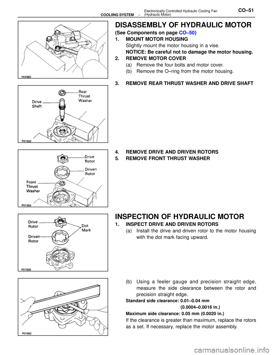
DISASSEMBLY OF HYDRAULIC MOTOR
(See Components on page CO±50)
1. MOUNT MOTOR HOUSING Slightly mount the motor housing in a vise.
NOTICE: Be careful not to damage the motor housing.
2. REMOVE MOTOR COVER (a) Remove the four bolts and motor cover.
(b) Remove the O±ring from the motor housing.
3. REMOVE REAR THRUST WASHER AND DRIVE SHAFT
4. REMOVE DRIVE AND DRIVEN ROTORS
5. REMOVE FRONT THRUST WASHER
INSPECTION OF HYDRAULIC MOTOR
1. INSPECT DRIVE AND DRIVEN ROTORS (a) Install the drive and driven rotor to the motor housingwith the dot mark facing upward.
(b) Using a feeler g auge and precision straight edge,
measure the side clearance between the rotor and
precision straight edge.
Standard side clearance: 0.01±0.04 mm
(0.0004±0.0016 in.)
Maximum side clearance: 0.05 mm (0.0020 in.)
If the clearance is greater than maximum, replace the rotors
as a set. If necessary, replace the motor assembly.
±
COOLIING SYSTEM Electronically Controlled Hydraulic Cooling Fan
(Hydraulic Motor)CO±51
WhereEverybodyKnowsYourName