Page 1135 of 4087
SYSTEM CIRCUIT
OPERATION
When the ignition switch is turned ON, current from the battery flows from t\
erminal L of the alternator through
the IC regulator to terminal E, causing the discharge warning light to ligh\
t up. Then when the engine is started, the voltage output increases as the alt\
ernator rpm increases. When the
voltage output becomes greater than the battery voltage, current for recharging\
flows from terminal B. Simulta-
neously, volt age at terminal L increases and the potential difference between battery and terminal L disappears,
causing the discharge warning light to go off. When the voltage output exceeds the regulator adjustment volt-
age, the transistor inside the IC regulator regulates the voltage so tha\
t the voltage from the alternator remains
constant.
±
CHARGING SYSTEM System Circuit, OperationCH±3
WhereEverybodyKnowsYourName
Page 1138 of 4087

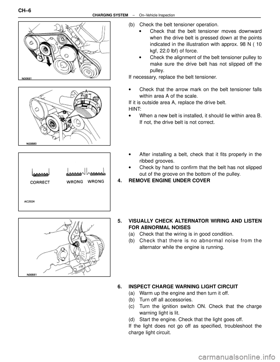
(b) Check the belt tensioner operation.w Check that the belt tensioner moves downward
when the drive belt is pressed down at the points
indicated in the illustration with approx. 98 N ( 10
kgf, 22.0 lbf) of force.
w Check the alignment of the belt tensioner pulley to
make sure the drive belt has not slipped off the
pulley.
If necessary, replace the belt tensioner.
w Check that the arrow mark on the belt tensioner falls
within area A of the scale.
If it is outside area A, replace the drive belt.
HINT:
w When a new belt is installed, it should lie within area B.
If not, the drive belt is not correct.
w After installing a belt, check that it fits properly in the
ribbed grooves.
w Check by hand to confirm that the belt has not slipped
out of the groove on the bottom of the pulley.
4. REMOVE ENGINE UNDER COVER
5. VISUALLY CHECK ALTERNATOR WIRING AND LISTEN FOR ABNORMAL NOISES
(a) Check that the wiring is in good condition.
(b) C h e c k t h a t t h e r e i s n o a bnormal noise from the
alternator while the engine is running.
6. INSPECT CHARGE WARNING LIGHT CIRCUIT (a) Warm up the engine and then turn it off.
(b) Turn off all accessories.
(c) Turn the ignition switch ON. Check that the charge
warning light is lit.
(d) Start the engine. Check that the light goes off.
If the light does not go off as specified, troubleshoot the
charge light circuit.
CH±6
±
CHARGING SYSTEM On±Vehicle Inspection
WhereEverybodyKnowsYourName
Page 1140 of 4087
8. INSPECT CHARGING CIRCUIT WITH LOAD(a) With the engine running at 2,000 rpm, turn on the highbeam headlights and place the heater blower switch at
ºHIº.
(b) Check the reading on the ammeter.
Standard amperage: 30 A or more
If the ammeter reading is less than standard amperage, re-
pair the alternator. (See page CH±9)
HINT: With the battery fully charged, the indication will some-
times be less than standard amperage.
9. REINSTALL ENGINE UNDER COVER
CH±8
±
CHARGING SYSTEM On±Vehicle Inspection
WhereEverybodyKnowsYourName
Page 1156 of 4087
LOCATION OF PLASTIC BODY PARTS
Outside Rear View Mirror (ABS)
Instrument Panel Safety Pad (PVC/PUR) Rear Spoiler (SMC)
Front Turn Signal Light (PC/PP)
Center Stop Light (PC)
Mead Light (PC/PP)
Head Light (PC/PP)
Front Bumper Extension
Mounting Bracket (PP)
Quarter Panel
Mud Guard (TPO)
Outside Moulding
Front Fender Mud Guard (TPO)
Front Spoiler (PUR) Cowl Top Ventilation Louver (PP)
Front Bumper Cover (PUR) Side Turn Signal Light (PMMA/ABS)
Cornering Light (PC)
HINT:
wResin material differs with model.
/ Made up of 2 or more kinds of materials.
PLASTIC BODY PARTSPP-4
WhereEverybodyKnowsYourName
Page 1158 of 4087
Steering Wheel Pad (PUR)A/C and Blower Unit (PP) Luggage Compartment Door
Striker Cover (PP)
Fuel Filler Opening
Lid (PBT)Rear Combination
Light (PMMA/PC/PP)
Door Scuff Outside Plate (PP) Door Scuff Inside Plate (PP)
Quarter Ventilation Duct (PP) License Plate
Light (PC/PP)
Rear Under Side Cover (PUR)
Rear Bumper Cover (PUR)
HINT:
wResin material differs with model.
/ Made up of 2 or more kinds of materials.
PLASTIC BODY PARTSPP-6
WhereEverybodyKnowsYourName
Page 1195 of 4087
FRONT DOOR PANEL (CUT)
REMOVAL
Cut and Join
LocationCut and Join Location
Heat Slightly Hemming Location
Disc Sander
1. Cut and join the parts at the location shown above.
2. After grinding off the hemming location, remove the outer panel.
HINT: Slightly heating the outer panel will soften thesealer and make removal easier.
BODY PANEL REPLACEMENTRE-38
WhereEverybodyKnowsYourName
Page 1199 of 4087
mm in.5 0.20
INSTALLATION
Butt Weld
Body Sealer
Butt Weld
Body Sealer
about 5 mm
1. Before temporarily installing the new parts, apply body sealer to the wheel arch.
HINT:
1) Apply body sealer about 5 mm (0.20 in.) from the flange, avoiding any oozing.
2) Apply sealer evenly, about 3 - 4 mm (0.12 - 0.16 in.) in diameter.
3) For other sealing points, refer to section AR.
2. Temporarily install the new parts and check the fit of the front door, luggage compartment
door and rear combination light.
3. Apply foamed material to the pillar section.
HINT: For the foamed material application areas, refer to page AP-4.
BODY PANEL REPLACEMENTRE-42
WhereEverybodyKnowsYourName
Page 1202 of 4087
mm in.5 0.20
INSTALLATION
Butt Weld
LiningBody Sealer
Butt Weld Braze
Body Sealer
about 5 mm
1. Before temporarily installing the new parts, ap- ply body sealer to the wheel arch.
HINT:
1) Apply body sealer about 5 mm (0.20 in.) from the flange, avoiding any oozing.
2) Apply sealer evenly, about 3 - 4 mm (0.12 - 0.16 in.) diameter.
3) For other sealing points, refer to section AR.
2. Temporarily install the new parts and check the fit of the luggage compartment door and
rear combination light.
3. Before welding, cut the lining away from the weld seams a little.
BODY PANEL REPLACEMENTRE-45
WhereEverybodyKnowsYourName