Page 2694 of 4087
CIRCUIT DESCRIPTION (Cont'd)
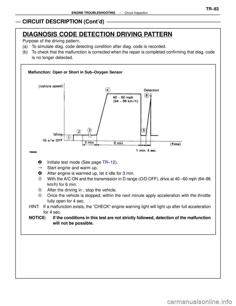
DIAGNOSIS CODE DETECTION DRIVING PATTERN
Purpose of the driving pattern.
(a) To simulate diag. code detecting condition after diag. code is recorded.
(b) To check that the malfunction is corrected when the repair is completed co\
nfirming that diag. codeis no longer detected.
Malfunction: Open or Short in Sub±Oxygen Sensor
�Initiate test mode (See page TR±12).
�Start engine and warm up.
�After engine is warmed up, let it idle for 3 min.
�With the A/C ON and the transmission in D range (O/D OFF), drive at 40 ±\
60 mph (64±96
km/h) for 6 min.
�After the driving in , stop the vehicle.
�Once the vehicle is stopped, within the next minute apply acceleration w\
ith the throttle
fully open for 4 sec.
HINT: If a malfunction exists, the ºCHECKº engine warning light will light\
up after full acceleration for 4 sec.
NOTICE: If the conditions in this test are not strictly followed, detection of the\
malfunction will not be possible.
±
ENGINE TROUBLESHOOTING Circuit InspectionTR±83
WhereEverybodyKnowsYourName
Page 2699 of 4087
Diag. Code 31Air Flow Meter Circuit
CIRCUIT DESCRIPTION
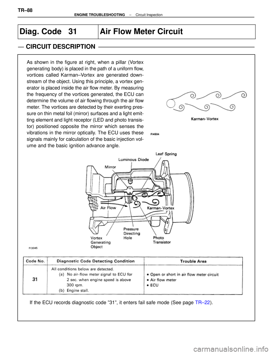
As shown in the figure at right, when a pillar (Vortex
generating body) is placed in the path of a uniform flow,
vortices called Karman±Vortex are generated down-
stream of the object. Using this principle, a vortex gen-
erator is placed inside the air flow meter. By measuring
the frequency of the vortices generated, the ECU can
determine the volume of air flowing through the air flow
meter. The vortices are detected by their exerting pres-
sure on thin metal foil (mirror) surfaces and a light emit-
ting element and light receptor (LED and photo transis-
tor) positioned opposite the mirror which senses the
vibrations in the mirror optically. The ECU uses these
signals mainly for calculation of the basic injection vol-
ume and the basic ignition advance angle.
If the ECU records diagnostic code º31º, it enters fail safe mode \
(See page TR±22).
TR±88
±
ENGINE TROUBLESHOOTING Circuit Inspection
WhereEverybodyKnowsYourName
Page 2712 of 4087
NGOK
OKNG
v
INSPECTION PROCEDURE
1Check output condition of diag. code 43.
C
OK
P
OK
C
Setting the test mode.
(2) Turn ignition switch OFF.
(2) Connect terminals TE2 and E1 of TDCL.
(2) Turn ignition switch ON.(Don't start the engine)
(2) Connect terminals TE1 and E1 of TDCL.
Check if code ª43º is output by the ªCHECKº engine
warning light.
Code ª43º is output.
Start the engine.
Check if the code ª43º disapears.
Code ª43º is not output.
Proceed to next circuit inspection shown on maxtric
chart (See page TR±35).
2Check for open in harness and connectors between engine & ECT ECU and st\
arter relay
(See page IN±27).
Repair or replace harness or connector.
Check and replace engine & ECT ECU.
±
ENGINE TROUBLESHOOTING Circuit InspectionTR±101
WhereEverybodyKnowsYourName
Page 2714 of 4087
CIRCUIT DESCRIPTION (Cont'd)
DIAGNOSIS CODE DETECTION DRIVING PATTERN
Purpose of the driving pattern.
(a) To simulate diag. code detecting condition after diag. code is recorded.
(b) To check that the malfunction is corrected when the repair is completed c\
onfirming that diag. code is nolonger detected.
Malfunction: Open or Short in Knock Sensor
�Start engine and warm up.
�After engine is warmed up, let it idle for 3 min.
�With the A/C ON, perform quick racing (5,000 rpm) three times.
(Rapidly depress the accelerator pedal and suddenly release it.)
HINT: If a malfunction exists, the ºCHECKº engine warning light will lig\
ht up when sudden racing is performed.
NOTICE: If the conditions in this test are not strictly followed, detection of t\
he malfunction will
not be possible.
±
ENGINE TROUBLESHOOTING Circuit InspectionTR±103
WhereEverybodyKnowsYourName
Page 2719 of 4087
Diag. Code 71
EGR System Malfunction (Only for USA
spec.)
CIRCUIT DESCRIPTION
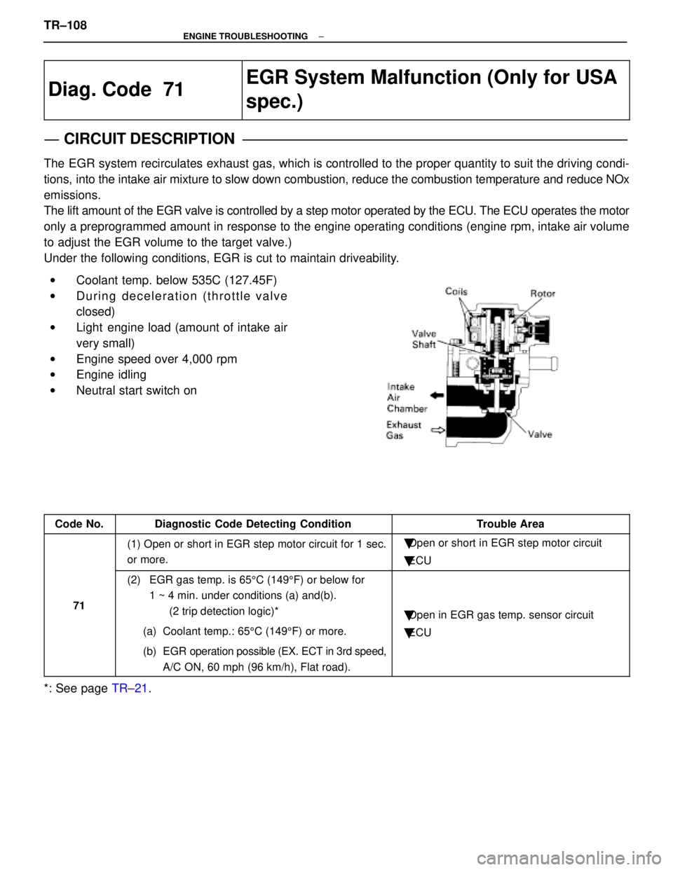
The EGR system recirculates exhaust gas, which is controlled to the proper quantity to suit the driv\
ing condi-
tions, into the intake air mixture to slow down combustion, reduce the combust\
ion temperature and reduce NOx
emissions.
The lift amount of the EGR valve is controlled by a step motor operated \
by the ECU. The ECU operates the motor
only a preprogrammed amount in response to the engine operating conditions (\
engine rpm, intake air volume
to adjust the EGR volume to the target valve.)
Under the following conditions, EGR is cut to maintain driveability.
wCoolant temp. below 535C (127.45F)
w During deceleration (throttle valve
closed)
w Light engine load (amount of intake air
very small)
w Engine speed over 4,000 rpm
w Engine idling
w Neutral start switch on
Code No.Diagnostic Code Detecting ConditionTrouble Area
(1) Open or short in EGR step motor circuit for 1 sec.
or more.�Open or short in EGR step motor circuit
� ECU
71
(2) EGR gas temp. is 65 5C (149 5F) or below for
1 ~ 4 min. under conditions (a) and(b).
(2 trip detection logic)*
(a) Coolant temp.: 65 5C (149 5F) or more.
(b) EGR operation possible (EX. ECT in 3rd speed, A/C ON, 60 mph (96 km/h), Flat road).
�Open in EGR gas temp. sensor circuit
� ECU
*: See page TR±21.
TR±108
±
ENGINE TROUBLESHOOTING
WhereEverybodyKnowsYourName
Page 2720 of 4087
CIRCUIT DESCRIPTION (Cont'd)
DIAGNOSIS CODE DETECTION DRIVING PATTERN
Purpose of the driving pattern.
(a) To simulate diag. code detecting condition after diag. code is recorded.
(b) To check that the malfunction is corrected when the repair is completed c\
onfirming that diag. code is nolonger detected.
�Initiate test mode (See page TR±12).
�Start engine and warm up.
�After engine is warmed up, let it idle for 3 min.
�With the A/C ON and transmission in D range (O/D OFF), drive at 40±\
70 mph for 4 min.
HINT: If a malfunction exists, the ºCHECKº engine warning light will light up at 1±4 min. of driving at 40±70 mph (64±112 km/h).
NOTICE: If the conditions in this test are not strictly followed, detection of the\
malfunction will not be possible.
Malfunction: Open in EGR gas temp. sensor circuit
±
ENGINE TROUBLESHOOTING Circuit InspectionTR±109
WhereEverybodyKnowsYourName
Page 2725 of 4087
Diag. Code 78Fuel Pump Control Circuit
CIRCUIT DESCRIPTION
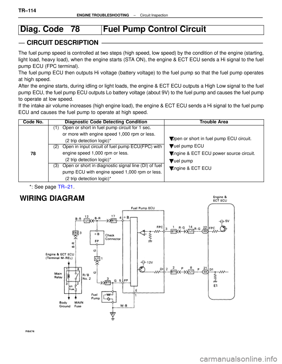
The fuel pump speed is controlled at two steps (high speed, low speed) by\
the condition of the engine (starting,
light load, heavy load), when the engine starts (STA ON), the engine & ECT ECU sends a Hi signal to the fuel
pump ECU (FPC terminal).
The fuel pump ECU then outputs Hi voltage (battery voltage) to the fuel p\
ump so that the fuel pump operates
at high speed.
After the engine starts, during idling or light loads, the engine & ECT ECU o\
utputs a High Low signal to the fuel
pump ECU, the fuel pump ECU outputs Lo battery voltage (about 9V) to the f\
uel pump and causes the fuel pump
to operate at low speed.
If the intake air volume increases (high engine load), the engine & ECT \
ECU sends a Hi signal to the fuel pump
ECU and causes the fuel pump to operate at high speed.
Code No.Diagnostic Code Detecting ConditionTrouble Area
(1) Open or short in fuel pump circuit for 1 sec. or more with engine speed 1,000 rpm or less.
(2 trip detection logic)*
�Open or short in fuel pump ECU circuit.
78
(2) Open in input circuit of fuel pump ECU(FPC) with
engine speed 1,000 rpm or less.
(2 trip detection logic)*�Fuel pump ECU
� Engine & ECT ECU power source circuit.
� Fuel pump
(3) Open or short in diagnostic signal line (DI) of fuel
pump ECU with engine speed 1,000 rpm or less.
(2 trip detection logic)*
�Fuel um
�Engine & ECT ECU
*: See page TR±21.
WIRING DIAGRAM
TR±114±
ENGINE TROUBLESHOOTING Circuit Inspection
WhereEverybodyKnowsYourName
Page 2731 of 4087
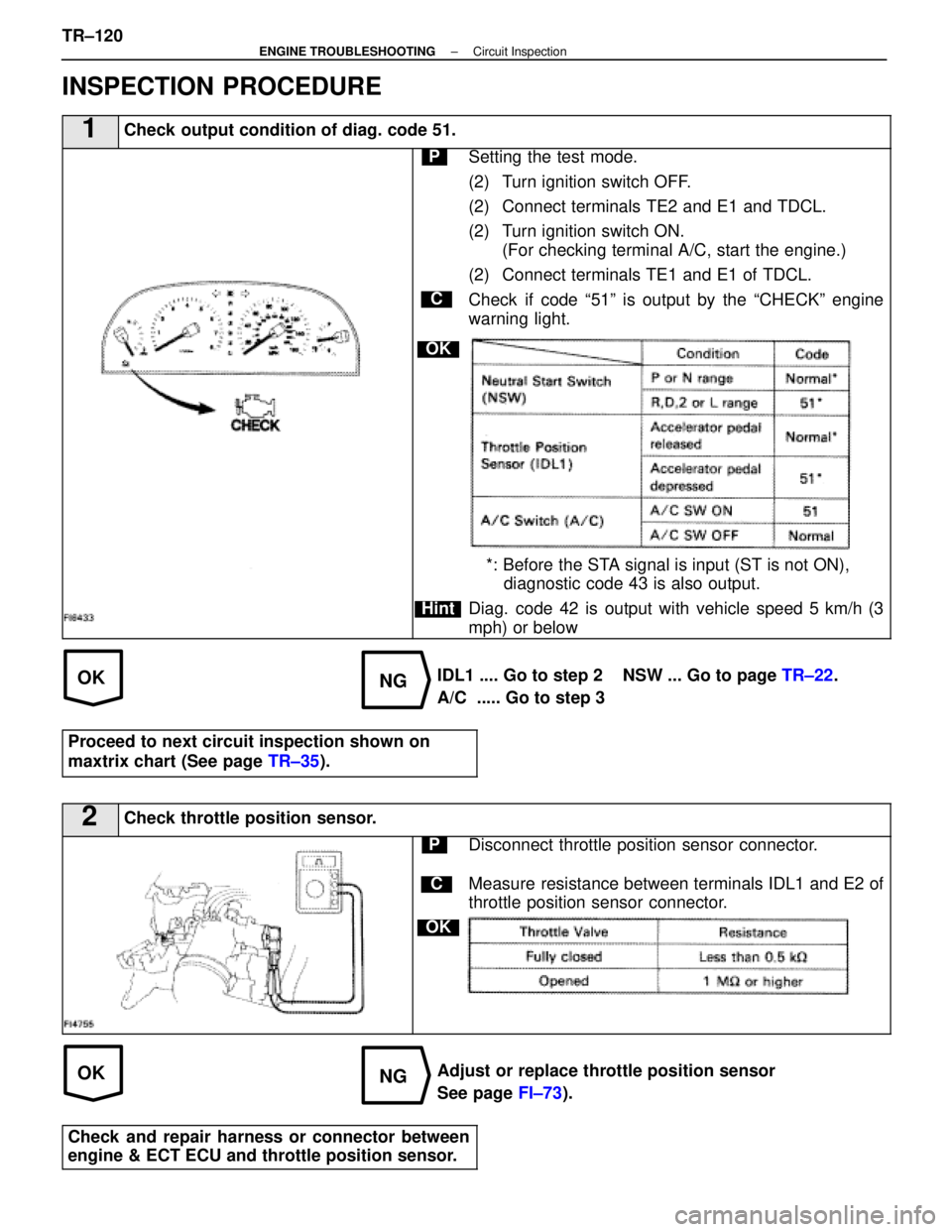
OKNG
OKNG
INSPECTION PROCEDURE
1Check output condition of diag. code 51.
C
OK
Hint
PSetting the test mode.
(2) Turn ignition switch OFF.
(2) Connect terminals TE2 and E1 and TDCL.
(2) Turn ignition switch ON.(For checking terminal A/C, start the engine.)
(2) Connect terminals TE1 and E1 of TDCL.
Check if code ª51º is output by the ªCHECKº engine
warning light.
*: Before the STA signal is input (ST is not ON), diagnostic code 43 is also output.
Diag. code 42 is output with vehicle speed 5 km/h (3
mph) or below
IDL1 .... Go to step 2 NSW ... Go to page TR±22.
A/C ..... Go to step 3
Proceed to next circuit inspection shown on
maxtrix chart (See page TR±35).
2Check throttle position sensor.
C
OK
PDisconnect throttle position sensor connector.
Measure resistance between terminals IDL1 and E2 of
throttle position sensor connector.
Adjust or replace throttle position sensor
See page FI±73).
Check and repair harness or connector between
engine & ECT ECU and throttle position sensor.
TR±120±
ENGINE TROUBLESHOOTING Circuit Inspection
WhereEverybodyKnowsYourName