Page 2757 of 4087

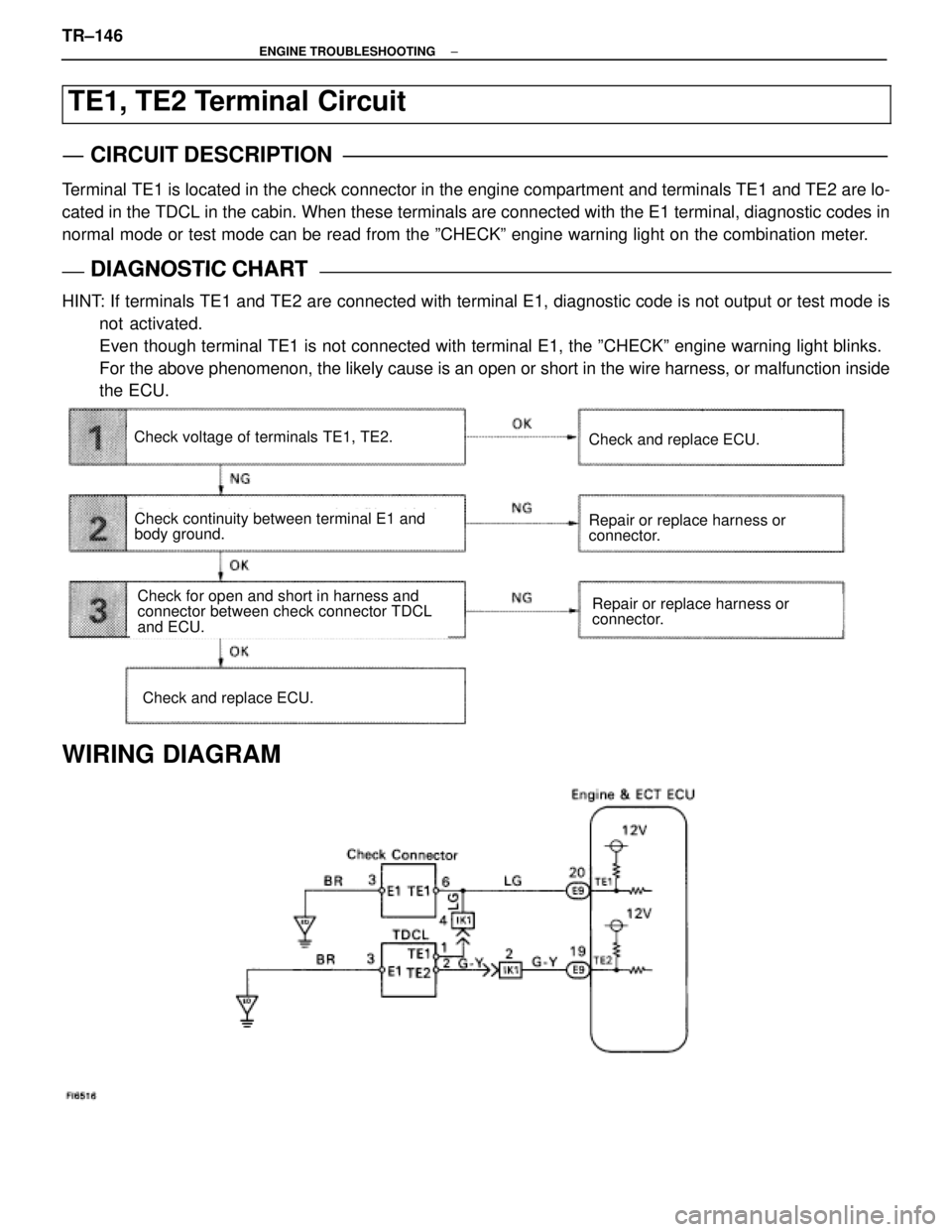
TE1, TE2 Terminal Circuit
CIRCUIT DESCRIPTION
Terminal TE1 is located in the check connector in the engine compartment and terminals T\
E1 and TE2 are lo-
cated in the TDCL in the cabin. When these terminals are connected with \
the E1 terminal, diagnostic codes in
normal mode or test mode can be read from the ºCHECKº engine warning lig\
ht on the combination meter.
DIAGNOSTIC CHARTDIAGNOSTIC CHART
HINT: If terminals TE1 and TE2 are connected with terminal E1, diagnostic code is not output or test mode isnot activated.
Even though terminal TE1 is not connected with terminal E1, the ºCHEC\
Kº engine warning light blinks.
For the above phenomenon, the likely cause is an open or short in the wire \
harness, or malfunction inside
the ECU.
Check continuity between terminal E1 and
body ground.
Repair or replace harness or
connector.Check for open and short in harness and
connector between check connector TDCL
and ECU.
Check voltage of terminals TE1, TE2.
Check and replace ECU.
Repair or replace harness or
connector.
Check and replace ECU.
WIRING DIAGRAM
TR±146±
ENGINE TROUBLESHOOTING
WhereEverybodyKnowsYourName
Page 2759 of 4087

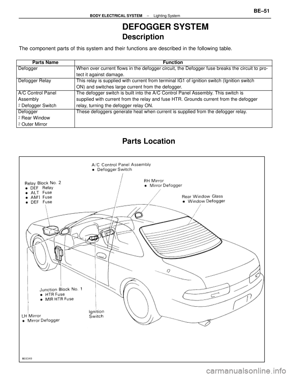
DEFOGGER SYSTEM
Description
The component parts of this system and their functions are described in the\
following table.
��������� ���������Parts Name������������������\
���������� ������������������\
����������Function
��������� ���������Defogger������������������\
���������� ������������������\
����������When over current flows in the defogger circuit, the Defogger fuse break\
s the circuit to pro-
tect it against damage.
��������� �
��������
���������
Defogger Relay������������������\
���������� �
������������������\
���������
������������������\
����������
This relay is supplied with current from terminal IG1 of ignition switch\
(Ignition switch
ON) and switches large current from the defogger.
��������� �
��������
���������
A/C Control Panel
Assembly
�
Defogger Switch������������������\
���������� �
������������������\
���������
������������������\
����������
The defogger switch is built into the A/C Control Panel Assembly. This switch is
supplied with current from the relay and fuse HTR. Grounds current from \
the defogger
relay, turning the defogger relay ON.
��������� �
��������
�
��������
���������
Defogger
�
Rear Window
� Outer Mirror������������������\
���������� �
������������������\
���������
�
������������������\
���������
������������������\
����������
These defoggers generate heat when current is supplied from the defogger\
relay.
Parts Location
±
BODY ELECTRICAL SYSTEM Lighting SystemBE±51
WhereEverybodyKnowsYourName
Page 2761 of 4087

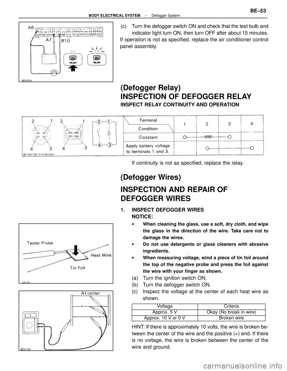
(c) Turn the defogger switch ON and check that the test bulb andindicator light turn ON, then turn OFF after about 15 minutes.
If operation is not as specified, replace the air conditioner control
panel assembly.
(Defogger Relay)
INSPECTION OF DEFOGGER RELAY
INSPECT RELAY CONTINUITY AND OPERATION
If continuity is not as specified, replace the relay.
(Defogger Wires)
INSPECTION AND REPAIR OF
DEFOGGER WIRES
1. INSPECT DEFOGGER WIRESNOTICE:
w When cleaning the glass, use a soft, dry cloth, and wipe
the glass in the direction of the wire. Take care not to
damage the wires.
w Do not use detergents or glass cleaners with abrasive
ingredients.
w When measuring voltage, wind a piece of tin foil around
the top of the negative probe and press the foil against
the wire with your finger as shown.
(a) Turn the ignition switch ON.
(b) Turn the defogger switch ON.
(c) Inspect the voltage at the center of each heat wire as
shown.
���������� ����������Voltage���������� ����������Criteria
����������Approx. 5 V����������Okay (No break in wire)���������� ����������Approx. 10 V or 0 V���������� ����������Broken wire
HINT: If there is approximately 10 volts, the wire is broken be-
tween the center of the wire and the positive (+) end. If there
is no voltage, the wire is broken between the center of the
wire and ground.
±
BODY ELECTRICAL SYSTEM Defogger SystemBE±53
WhereEverybodyKnowsYourName
Page 2767 of 4087
SYSTEM CIRCUIT
OPERATION
When the ignition switch is turned ON, current from the battery flows from t\
erminal L of the alternator through
the IC regulator to terminal E, causing the discharge warning light to ligh\
t up. Then when the engine is started, the voltage output increases as the alt\
ernator rpm increases. When the
voltage output becomes greater than the battery voltage, current for recharging\
flows from terminal B. Simulta-
neously, volt age at terminal L increases and the potential difference between battery and terminal L disappears,
causing the discharge warning light to go off. When the voltage output exceeds the regulator adjustment volt-
age, the transistor inside the IC regulator regulates the voltage so tha\
t the voltage from the alternator remains
constant.
±
CHARGING SYSTEM System Circuit, OperationCH±3
WhereEverybodyKnowsYourName
Page 2770 of 4087

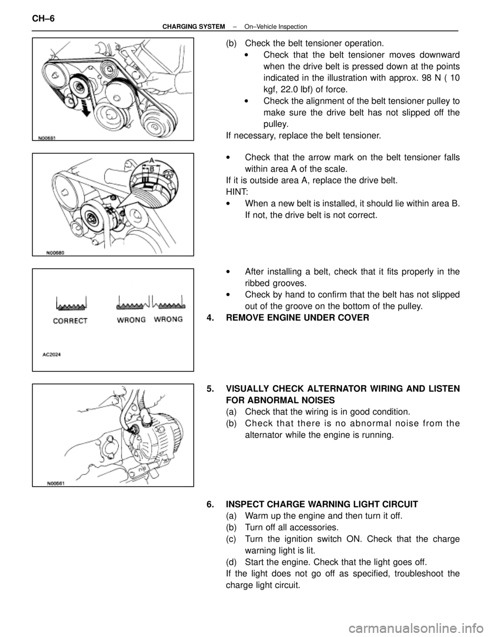
(b) Check the belt tensioner operation.w Check that the belt tensioner moves downward
when the drive belt is pressed down at the points
indicated in the illustration with approx. 98 N ( 10
kgf, 22.0 lbf) of force.
w Check the alignment of the belt tensioner pulley to
make sure the drive belt has not slipped off the
pulley.
If necessary, replace the belt tensioner.
w Check that the arrow mark on the belt tensioner falls
within area A of the scale.
If it is outside area A, replace the drive belt.
HINT:
w When a new belt is installed, it should lie within area B.
If not, the drive belt is not correct.
w After installing a belt, check that it fits properly in the
ribbed grooves.
w Check by hand to confirm that the belt has not slipped
out of the groove on the bottom of the pulley.
4. REMOVE ENGINE UNDER COVER
5. VISUALLY CHECK ALTERNATOR WIRING AND LISTEN FOR ABNORMAL NOISES
(a) Check that the wiring is in good condition.
(b) C h e c k t h a t t h e r e i s n o a bnormal noise from the
alternator while the engine is running.
6. INSPECT CHARGE WARNING LIGHT CIRCUIT (a) Warm up the engine and then turn it off.
(b) Turn off all accessories.
(c) Turn the ignition switch ON. Check that the charge
warning light is lit.
(d) Start the engine. Check that the light goes off.
If the light does not go off as specified, troubleshoot the
charge light circuit.
CH±6
±
CHARGING SYSTEM On±Vehicle Inspection
WhereEverybodyKnowsYourName
Page 2772 of 4087
8. INSPECT CHARGING CIRCUIT WITH LOAD(a) With the engine running at 2,000 rpm, turn on the highbeam headlights and place the heater blower switch at
ºHIº.
(b) Check the reading on the ammeter.
Standard amperage: 30 A or more
If the ammeter reading is less than standard amperage, re-
pair the alternator. (See page CH±9)
HINT: With the battery fully charged, the indication will some-
times be less than standard amperage.
9. REINSTALL ENGINE UNDER COVER
CH±8
±
CHARGING SYSTEM On±Vehicle Inspection
WhereEverybodyKnowsYourName
Page 2804 of 4087
(b) Slightly lift the radiator, and disconnect the two oil cooler
hoses (for cooling fan) from the hose clamp on the
radiator fan shrould.
(c) Remove the radiator.
(d) Remove the two lower radiator supports.
10. REMOVE FAN SHROULD FROM RADIATOR Remove the four bolts and fan shrould.
INSTALLATION OF RADIATOR
(See Components on page CO±15)
1. INSTALL FAN SHROULD TO RADIATOR Install the fan shrould with the four bolts.
Torque: 4.9 N Vm (50 kgf Vcm, 43 in. Vlbf)
2. INSTALL RADIATOR
(a) Install the two lower radiator supports to the radiator.
(b) Place the radiator on the body bracket.
(c) Slightly lift the radiator, and connect the two oil coolerhoses (for cooling fan) to the hose clamp on the radiator
fan shrould.
CO±18
±
COOLIING SYSTEM Radiator
WhereEverybodyKnowsYourName
Page 2826 of 4087
9. INSTALL FRONT HOUSING(a) Install a new O±ring to the casing groove.
(b) Align the pin holes of the front housing with the straightpin.
(c) Apply a light coat of fluid on the threads and under the heads of the mounting bolts.
(d) Install the front housing with the five bolts.
Torque: 21 N Vm (210 kgf Vcm, 15 ft Vlbf)
10. INSTALL DRIVE SHAFT PRELOAD
(a) Check that the drive shaft rotates smoothly withoutabnormal noise.
(b) Temporarily install the pulley nut, and check the rotating torque.
Rotating torque:
0.3 N Vm (3.0 kgf Vcm, 2.6 in. Vlbf)
11. INSTALL PUMP PULLEY
(a) Slide the pulley onto the drive shaft.
(b) Measure the clearance between the pulley end anddrive shaft end.
Standard: 1.3±1.7 mm (0.051±0.067 in.)
Minimum: 1.0 mm (0.039 in.)
If the clearance is less than minimum, replace the pulley.
CO±40
±
COOLIING SYSTEM Electronically Controlled Hydraulic
Cooling Fan (Hydraulic Pump)
WhereEverybodyKnowsYourName