1991 FORD FESTIVA steering wheel
[x] Cancel search: steering wheelPage 40 of 454
Back To Article
AXLE SHAFT S - FRONT
1988-93 Drive Axles - FWD Axle Shafts
DESCRIPTION & OPERATION
Axle shafts transfer power from transaxle to driving wheels. All axle shafts consist of a shaft with a flexible Constant Velocity (CV) joint at
each end. Inner CV joint is coupled to transaxle by splines. Outer CV joint is splined to hub assembly and secured by axle shaft nut.
Three different types of axle shaft CV joints are used: Double Offset Joint (DOJ) or Rzeppa type, Birfield Joint (BJ) and the Tripot Joint (TJ).
CV joint boots protect CV joints by maintaining proper lubrication and preventing contaminants from entering joint. Boots must be replaced
when signs of leakage or cracks are present. Inner CV joint may be disassembled and serviced. Outer CV joint boot may be replaced, but outer
Birfield CV joint must NOT be disassembled. It must be replaced as an assembly, if faulty.
To prevent torsional vibration and torque steer on turbocharged Capri vehicles, an intermediate shaft and conventional axle shaft are used on
the right side. Both shafts are of similar length and are supported by a bearing, which is attached to engine.
CV JOINT IDENTIFICATION
TROUBLE SHOOTING
REMOVAL, DISASSEMBLY, REASSEMBLY & INSTALLATION
FWD AXLE SHAFTS
Removal
1. Raise and support vehicle. Remove lower underbody splash shields. Drain transaxle fluid. Remove front wheels and loosen axle shaft
lock nut. On Capri, remove stabilizer bar-to-control arm attaching nuts, bolt, washers and bushings. On Festiva, remove stabilizer bar
attaching nuts and bracket. On all models, remove joint clamp bolt from lower control arm. Pry downward and separate steering knuckle
from ball joint, taking care not to damage ball joint dust boot.
2. On Capri turbo, remove bolts securing intermediate shaft bearing bracket to engine. On all models, slowly pry axle shaft from transaxle
using a flat-tip screwdriver or pry bar. Axle is held into transaxle by a circlip fitted to the end of the axle. Remove axle shaft from wheel
hub. If difficult to remove, use axle puller to remove axle from drive hub. Remove axle shaft from transaxle. Plug transaxle openings
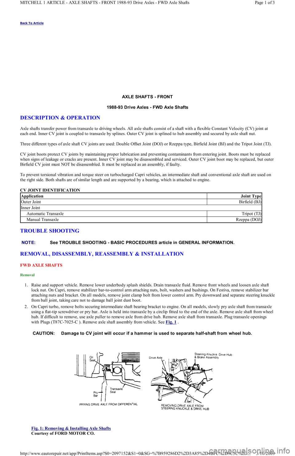
with Plugs (T87C-7025-C ). Remove axle shaft assembly from vehicle. See Fig. 1
.
Fig. 1: Removing & Installing Axle Shafts
Courtesy of FORD MOTOR CO.
ApplicationJoint Type
Outer JointBirfield (BJ)
In n er Jo in t
Automatic TransaxleTripot (TJ)
Manual TransaxleRzeppa (DOJ)
NOTE:See TROUBLE SHOOTING - BASIC PROCEDURES article in GENERAL INFORMATION.
CAUTION: Dam age to CV joint will occur if a ham mer is used to separate half-shaft from wheel hub.
Page 1 of 3 MITCHELL 1 ARTICLE - AXLE SHAFTS - FRONT 1988-93 Drive Axles - FWD Axle Shafts
3/10/2009 http://www.eautorepair.net/app/PrintItems.asp?S0=2097152&S1=0&SG=%7B959286D2%2D3A85%2D4BFC%2D9C5C%2D
...
Page 42 of 454
Installation (All)
1. To install axle shaft, reverse removal procedure. Always install a NEW retaining circlip. Check seals at both ends of axle shaft. If
necessary, replace seals prior to installation. Lubricate transaxle seal lip with transaxle oil. See Fig. 1
.
2. After installing axle shaft into transaxle, pull axle shaft outward by hand to ensure proper engagement of retaining circlip and snap ring.
Install axle shaft into wheel hub. Align suspension alignment marks and tighten nuts.
INTERMEDIATE SHAFT
Removal
Intermediate shaft and axle shaft are removed as an assembly. See FWD AXLE SHAFTS under REMOVAL, DISASSEMBLY,
REASSEMBLY & INSTALLATION.
Disassembly
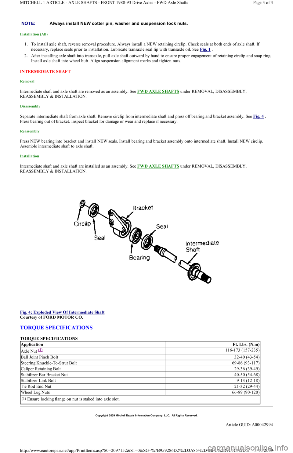
Separate intermediate shaft from axle shaft. Remove circlip from intermediate shaft and press off bearing and bracket assembly. See Fig. 4 .
Press bearing out of bracket. Inspect bracket for damage or wear and replace if necessary.
Reassembly
Press NEW bearing into bracket and install NEW seals. Install bearing and bracket assembly onto intermediate shaft. Install NEW circlip.
Assemble intermediate shaft to axle shaft.
Installation
Intermediate shaft and axle shaft are installed as an assembly. See FWD AXLE SHAFTS under REMOVAL, DISASSEMBLY,
REASSEMBLY & INSTALLATION.
Fig. 4: Exploded View Of Intermediate Shaft
Courtesy of FORD MOTOR CO.
TORQUE SPECIFICATIONS
TORQUE SPECIFICATIONS NOTE:Always install NEW cotter pin, washer and suspension lock nuts.
ApplicationFt. Lbs. (N.m)
Axle Nut (1) 116-173 (157-235)
Ball Joint Pinch Bolt32-40 (43-54)
Steering Knuckle-To-Strut Bolt69-86 (93-117)
Caliper Retaining Bolt29-36 (39-49)
Stabilizer Bar Bracket Nut40-50 (54-68)
Stabilizer Link Bolt9-13 (12-18)
Tie Rod End Nut21-32 (29-44)
Wheel Lug Nuts66-89 (90-120)
(1)Ensure locking flange on nut is staked into axle slot.
Copyr ight 2009 Mitchell Repair Information Company, LLC. All Rights Reserved.
Article GUID: A00042994
Page 3 of 3 MITCHELL 1 ARTICLE - AXLE SHAFTS - FRONT 1988-93 Drive Axles - FWD Axle Shafts
3/10/2009 http://www.eautorepair.net/app/PrintItems.asp?S0=2097152&S1=0&SG=%7B959286D2%2D3A85%2D4BFC%2D9C5C%2D
...
Page 68 of 454

Shift Lock ActuatorShift Interlock Systems
Side Marker LightsExterior Lights
SIR Coil Assembly (Clockspring)Air Bag Restraint System
Slip Ring (Clockspring)Air Bag Restraint System; Steering Column Switches
SRS Control ModuleAir Bag Restraint System
Starter MotorStarters
Starter Interrupt RelayStarters
Starter SolenoidStarters
Starter RelayStarters
Steering Wheel Position SensorAnti-Lock Brakes
StoplightsExterior Lights
Stoplight SwitchEngine Performance; Cruise Control Systems; Anti-Lock Brakes
Sun Roof ECUPower Sun Roof
Sun Roof MotorPower Sun Roof
Sun Roof Position SensorPower Sun Roof
TaillightsExterior Lights
Throttle Position (TP) SensorEngine Performance
Torque Converter Clutch Solenoid/SwitchEngine Performance
Traction Control SwitchAnti-Lock Brakes
Trailer Tow ConnectorExterior Lights
Trailer Tow RelayExterior Lights
Transmission/TransaxleEngine Performance
Transmission Control Module (TCM)Engine Performance; Starters
Transmission Range SensorStarters; Back-Up Lights; Engine Performance
Transmission Range SwitchBack-Up Lights; Engine Performance; Anti-Theft System
Turn Signal FlasherExterior Lights
Tu r n S ign a l Ligh t sExterior Lights
Twilight Sentinel SwitchHeadlight Systems; Daytime Running Lights
Vapor Canister Leak Detection PumpEngine Performance
Vehicle Control Module (VCM)Engine Performance
Vehicle Dynamic ModuleElectronic Suspension
Vehicle Speed Control ServoCruise Control Systems
Vehicle Speed SensorData Link Connectors; Analog Instrument Panels; Cruise Control
Systems; Electronic Suspension
Voltage RegulatorGenerators & Regulators
Water-In-Fuel SensorEngine Performance; Analog Instrument Panels
Wheel Speed SensorsAnti-Lock Brakes
Window Timer ModulePower Convertible Top
Windshield Intermittent Wiper RelayWiper/Washer Systems
Windshield Washer MotorWiper/Washer Systems
Wiper MotorWiper/Washer Systems
Copyr ight 2009 Mitchell Repair Information Company, LLC. All Rights Reserved.
Article GUID: A00130983
Page 6 of 6 MITCHELL 1 ARTICLE - GENERAL INFORMATION Using Mitchell1's Wiring Diagrams
3/10/2009 http://www.eautorepair.net/app/PrintItems.asp?S0=2097152&S1=0&SG=%7B959286D2%2D3A85%2D4BFC%2D9C5C%2D
...
Page 102 of 454

levels to proper level.
Removal (1.6L & 1.6L Turbo)
1. Relieve fuel pressure and discharge air conditioning system (if equipped). See FUEL PRESSURE RELEASE under REMOVAL &
INSTALLATION. Disconnect and remove battery, battery tray and battery tray support bracket.
2. Release wiring harness retaining straps from battery support tray. Disconnect windshield washer supply hose between fluid reservoir and
hood. Mark hinge locations and remove hood.
3. Disconnect intake air tube and wiring to ignition coil and vane airflow meter. Remove air cleaner/vane airflow meter assembly. Remove
air cleaner assembly support brackets. Disconnect intercooler hoses from turbocharger (if equipped).
4. Drain engine coolant and remove radiator. Disconnect accelerator cable, and remove retaining bracket from cam cover. Position cable to
one side.
5. Disconnect and plug fuel lines at fuel filter and pressure regulator. Disconnect power brake booster manifold vacuum hose from
manifold. Disconnect heater hoses at heater core tubes. Label and remove vacuum hoses located at throttle body.
6. For manual transaxle turbocharged vehicles, disconnect clutch cable and remove support bracket and cable from transmission. On non-
turbo vehicles, disconnect clutch slave hydraulic line. For automatic transaxle, remove transaxle cooler lines.
7. Disconnect starter wiring at starter. Remove harness from locating strap on bracket. Disconnect alternator wiring. Disconnect wiring
from engine coolant sensors located on rear of engine block. Remove ground connection at bracket on thermostat cover. Disconnect O2
sensor wire, main wiring harness connector, TPS connector (turbocharged only), knock sensor connector, distributor wiring and
transaxle wiring. Disconnect ground wire and strap at front of engine, and reinstall lifting eye.
8. Remove engine oil dipstick and retaining clip. Remove power steering pump from mounting bracket. Remove power steering pump
mounting bracket. With hoses attached, position pump aside. Remove upper air conditioning compressor retaining bolts (if equipped).
9. Raise vehicle on hoist. Drain engine oil and cooling system. On vehicles with air conditioning, remove lower air conditioning
compressor mounting bolts, and position compressor out of way.
10. Remove front wheels and tires. Remove front ball joints-to-ste e r in g kn u c kl e s r e t a in in g b o l t s. R e mo ve sp l a sh gu a r d s. Dr a in t ransmission
oil and remove half shafts from differential. Remove front exhaust pipe bracket located on lower side of engine. Disconnect front
exhaust pipe from exhaust manifold, or turbocharger (if equipped).
11. Remove frame support bar-to-engine support bolt. Loosen right control arm bolt and, pivot support bar downward. Disengage rubber
exhaust hangers located directly behind catalytic converter. Allow exhaust system to hang down 6 inches, and support system with
mechanic's wire. Unbolt shift linkage and stabilizer bar at transaxle. Remove nuts from front and rear engine mounts, and lower vehicle.
12. Attach chains onto lift eyes at ends of cylinder head, and support engine with hoist. Remove RH engine mount through bolt. Raise
engine off mounts and slightly pivot engine/transaxle assembly. Disconnect oil pressure sensor and route starter/alternator wiring
harness from engine. Carefully lift engine/transaxle assembly, turn assembly while raising to clear brake master cylinder, shift linkage
universal joint, radiator support and air conditioning lines (if equipped).
13. Remove intake manifold support bracket. Remove gusset plate(s) (if equipped). Remove starter. Remove transaxle-to-engine retaining
bolts. Identify bolts to ensure correct installation. Separate transaxle from engine. On manual transaxle, remove pressure plate, clutch
disc and flywheel. On automatic transaxle, remove flexplate.
Installation (1.6L & 1.6L Turbo)
1. Install transaxle to engine in reverse order of removal. Attach hoist to engine/transaxle assembly and position assembly in vehicle.
Before engine contacts mounts, route starter, alternator and oil pressure sensor wiring, and connect oil pressure sensor. Lower engine
until front mount seats on crossmember. Install through bolt on RH engine mount. DO NOT tighten bolt.
2. Remove hoist. Raise vehicle and support with jackstands. Align rear engine mount to crossmember, and install retaining nuts to front
and rear engine mounts. Tighten nuts to specification. See TORQUE SPECIFICATIONS
table at end of article.
3. On manual transaxles, connect shift coupling and stabilizer. Tighten to specification. On automatic transaxles, connect shift linkage and
oil cooler lines. Tighten linkage retaining bolt, shift cable pivot and oil cooler hose clamps to specification. Connect front exhaust pipe
to manifold (or turbocharger). Install exhaust pipe to support bracket. Tighten bolts to specification. Tighten manifold (or turbocharger)
to specification. Attach rubber exhaust hangers. Position cross brace. Tighten retaining nut and bolt and right control arm front bolt.
4. Install drive axles. Install ball joint retaining bolts and tighten to specification. Mount A/C Compressor to engine (if equipped). Tighten
lower retaining bolts to specification. Install splash guards. Install tire and wheel assemblies. Tighten retaining nuts to specification.
5. Lower vehicle. Install upper A/C compressor retaining bolts (if equipped). Tighten bolts to specification. Tighten RH engine mo u n t
through bolt to specification. Connect alternator wiring.
6. Position power steering pump bracket on stud. Lower pump into engine compartment. Install power steering pump bracket retaining
bolts and nut. Tighten to specification. Install power steering pump and belt. Tighten adjustment nut and pivot bolt to specification.
7. Install engine oil dipstick and retaining clip. Install ground strap and ground wire to cylinder head. Install clutch cable (if equipped).
Connect clutch hydraulic line if equipped with manual transaxle or naturally aspirated. Connect transmission electrical connectors.
Connect fuel lines to fuel filter and pressure regulator. Install intake air tube to throttle body.
8. Install intercooler hoses on turbocharged models. Install air cleaner assembly brackets. Install air cleaner assembly with airflow meter
attached. Install intake air tube. Install coil and airflow meter connectors. Connect coolant crankcase and air bypass hoses. Install
vacuum hoses as noted in disassembly.
9. Connect accelerator cable. Install retaining bracket. Install power brake booster hose. Remove speedometer cable from transaxle. Fill
transaxle to specification. See CAPACITIES in SERVICE & ADJUSTMENT SPECIFICATIONS article. Install speedometer cable.
Connect speedometer cable connector. Fill engine oil to capacity.
10. Install radiator/fan assembly. Tighten bracket retaining bolts to specification. Connect coolant hoses and fan electrical connector. Fill
coolant to specification.
11. Install hood and connect washer hose. Install battery tray support, battery tray, battery and battery hold-down. Connect battery
terminal. Evacuate and charge air conditioning system (if equipped). Road test vehicle and inspect for leaks.
INTAKE MANIFOLD
Removal (1.3L)
CAUT ION: DO NOT allow com pressor to hang by hoses. T ie up com pressor with m echanic's wire.
Page 2 of 19 MITCHELL 1 ARTICLE - ENGINE OVERHAUL 1991-92 FORD MOTOR CO. ENGINES 1.3L & 1.6L 4-Cylinder
3/10/2009 http://www.eautorepair.net/app/PrintItems.asp?S0=2097152&S1=0&SG=%7B959286D2%2D3A85%2D4BFC%2D9C5C%2D
...
Page 107 of 454
Remove timing belt covers, See TIMING BELT COVER procedure to remove timing belt from this engine.
Installation (1.6L)
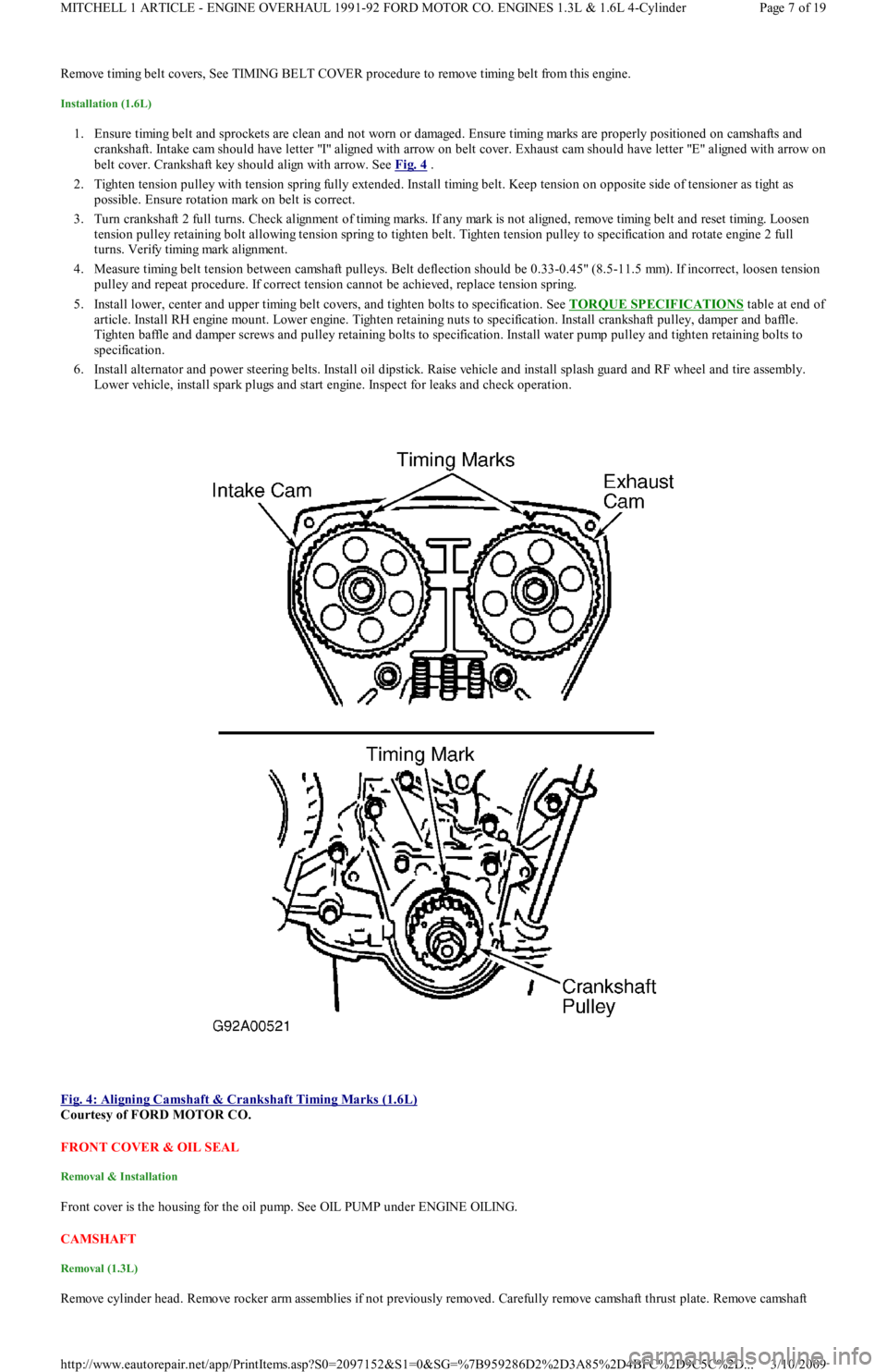
1. Ensure timing belt and sprockets are clean and not worn or damaged. Ensure timing marks are properly positioned on camshafts and
crankshaft. Intake cam should have letter "I" aligned with arrow on belt cover. Exhaust cam should have letter "E" aligned with arrow on
belt cover. Crankshaft key should align with arrow. See Fig. 4
.
2. Tighten tension pulley with tension spring fully extended. Install timing belt. Keep tension on opposite side of tensioner as tight as
possible. Ensure rotation mark on belt is correct.
3. Turn crankshaft 2 full turns. Check alignment of timing marks. If any mark is not aligned, remove timing belt and reset timing. Lo o se n
tension pulley retaining bolt allowing tension spring to tighten belt. Tighten tension pulley to specification and rotate engine 2 full
turns. Verify timing mark alignment.
4. Measure timing belt tension between camshaft pulleys. Belt deflection should be 0.33-0.45" (8.5-11.5 mm). If incorrect, loosen tension
pulley and repeat procedure. If correct tension cannot be achieved, replace tension spring.
5. Install lower, center and upper timing belt covers, and tighten bolts to specification. See TORQUE SPECIFICATIONS
table at end of
article. Install RH engine mount. Lower engine. Tighten retaining nuts to specification. Install crankshaft pulley, damper and baffle.
Tighten baffle and damper screws and pulley retaining bolts to specification. Install water pump pulley and tighten retaining bolts to
specification.
6. Install alternator and power steering belts. Install oil dipstick. Raise vehicle and install splash guard and RF wheel and tire assembly.
Lower vehicle, install spark plugs and start engine. Inspect for leaks and check operation.
Fig. 4: Aligning Camshaft & Crankshaft Timing Marks (1.6L)
Courtesy of FORD MOTOR CO.
FRONT COVER & OIL SEAL
Removal & Installation
Front cover is the housing for the oil pump. See OIL PUMP under ENGINE OILING.
CAMSHAFT
Removal (1.3L)
Remove cylinder head. Remove rocker arm assemblies if not previously removed. Carefully remove camshaft thrust plate. Remove camsh aft
Page 7 of 19 MITCHELL 1 ARTICLE - ENGINE OVERHAUL 1991-92 FORD MOTOR CO. ENGINES 1.3L & 1.6L 4-Cylinder
3/10/2009 http://www.eautorepair.net/app/PrintItems.asp?S0=2097152&S1=0&SG=%7B959286D2%2D3A85%2D4BFC%2D9C5C%2D
...
Page 111 of 454
bearing oil seal. To complete installation, reverse removal procedure.
WATER PUMP
Removal & Installation (1.3L)
Remove timing belt. Drain cooling system. Remove lower radiator hose and heater return hose from water pump. Remove water pump
retaining bolts and water pump. Clean gasket mounting surface and replace gasket. To install, reverse removal procedure.
Removal (1.6L)
1. Remove timing belt. See TIMING BELT . Drain cooling system. Remove timing belt tensioner and idler pulleys. Remove oil dipstick
bracket retaining bolt.
2. Remove power steering pump from retaining bracket, leaving hoses attached. Remove power steering bracket and position power
steering pump to one side. Remove water pump outlet. Remove water pump retaining bolts and water pump.
Installation (1.6L)
1. Clean all gasket surfaces. Transfer rubber belt cover seal to new water pump (if required). Position water pump with new gasket and
install retaining bolts. Install pump outlet with new gasket and "O" ring. See TORQUE SPECIFICATIONS
table at end of article.
2. Install oil dipstick retaining bolt. Install timing belt tensioner and idler pulleys. Install power steering pump bracket. Install power
steering pump. Tighten all bolts and nuts to specification. See TORQUE SPECIFICATIONS
table at end of article.
3. Install timing belt. Fill cooling system. Start engine and check for leaks and proper system function.
OIL PAN
Removal (1.3L)
Disconnect battery ground cable. Raise vehicle and drain engine oil. Remove flywheel housing dust cover. Remove oil pan retaining bolts,
nuts and stiffeners. Rotate crankshaft while removing oil pan. Remove baffle plate from oil pan. Clean gasket mating surfaces thoroughly.
Installation (1.3L)
Ensure gasket surfaces are clean. Apply oil resistant sealer to front and rear engine covers and across joint line of cylinder block.
Removal (1.6L)
1. Raise vehicle and drain engine oil. Remove frame brace retaining bolt. Loosen RH "A" arm front bolt, and pivot brace downward.
Disconnect front exhaust pipe from exhaust manifold (or turbocharger). Remove exhaust pipe bracket retaining bolts. Loosen rubber
exhaust hangers at catalytic converter.
2. Allow exhaust to hang supported by mechanic's wire. Disconnect turbocharger oil return hose (if equipped). Remove oil pan retaining
bolts. Carefully pry oil pan loose from cylinder block.
Installation (1.6L)
1. Clean pan and block gasket surfaces. Apply Gasket Sealant (E3AZ-19562-A) to new front and rear pan seals. Install seals to cylinder
block. Apply Gasket Sealant (E3AZ-19562-A) to oil pan gasket surface. See Fig. 8
. Install oil pan and tighten pan retaining bolts to
specification. See TORQUE SPECIFICATIONS
table at end of article.
2. Connect turbocharger oil return hose (if equipped). Install rubber exhaust hanger to brackets. Install new gasket and connect fro n t
exhaust pipe to exhaust manifold (or turbocharger). Install front exhaust pipe bracket. Tighten nuts and bolts to specification.
3. Pivot frame brace into position. Tighten retaining bolt to crossmember and RH "A" arm front retaining bolt to specification. Lower
vehicle, fill with oil and start engine. Check for oil leaks and system operation. NOTE:Raise engine slightly with floor jack, if required, to gain clearance for water pum p rem oval.
CAUT ION: DO NOT force a pry tool between cylinder block and oil pan.
Page 11 of 19 MITCHELL 1 ARTICLE - ENGINE OVERHAUL 1991-92 FORD MOTOR CO. ENGINES 1.3L & 1.6L 4-Cylinder
3/10/2009 http://www.eautorepair.net/app/PrintItems.asp?S0=2097152&S1=0&SG=%7B959286D2%2D3A85%2D4BFC%2D9C5C%2D
...
Page 163 of 454

POWER STEERING PRESSURE SWITCH
1. Start engine and run it at idle. Remove connector from switch. Connect ohmmeter to switch terminals. Turn steering wheel from side to
side while observing ohmmeter.
2. Replace power steering switch if continuity does not exist with front wheels turned, or if continuity exists with wheels straight ahead.
THROTTLE POSITION SENSOR (1.6L)
Unplug connector from sensor. Connect ohmmeter to sensor terminals TP and SIGRTN (Orange and Blue/Yellow wires on mating connector).
Measure resistance at each throttle opening specified in THROTTLE POSITION SENSOR RESISTANCE
. Replace sensor if resistance is
not within specification.
THROTTLE POSITION SENSOR RESISTANCE
THROTTLE POSITION SWITCH (1.3L)
1. Ensure idle speed and ignition timing are adjusted to specification. Stop engine. Disconnect negative battery cable.
2. Unplug TPS connector at throttle body. Insert appropriate feeler gauge between throttle stop screw and stop lever. Check for continuity
between specified terminals on TPS connector. See ON-VEHICLE ADJUSTMENTS article and TPS CONTINUITY table.
TPS CONTINUITY
VANE AIRFLOW (VAF) METER
1. Check all wiring, harnesses, connectors and components for evidence of damage, overheating, shorting or looseness. If any defect exists,
repair as necessary.
2. Inspect vane airflow meter for damage and ensure measuring plate moves smoothly. Install BOB. Turn ignition on. Measure voltage
between BOB test pins VAF and ground on 1.3L, or between VAF and SIGRTN on 1.6L. Voltage measurements must be as specified in
VANE AIRFLOW METER VOLTAG
.
VANE AIRFLOW METER VOLTAGE
VANE AIR TEMPERATURE (VAT) SENSOR
1. Unplug connector from VAF meter. On 1.3L, connect ohmmeter to terminals VAT and ground (Green/Black and Black wires on mating
connector). On 1.6L, connect ohmmeter to VAF meter terminals VAT and SIGRTN (Brown and Blue/Yellow wires on mating
connector).
2. Measure intake air temperature. Measure resistance between specified terminals. See VANE AIR TEMPERATURE RESISTANCE
.
Replace VAF if resistance is not as specified.
Throttle Opening(1) Ohms
1/8989
1/41104
3/81278
1/21462
5/81480
3/41459
7/81144
Fully Open1072
(1)Resistance may vary by plus or minus 15 percent.
CAUT ION: DO NOT tam per with throttle stop screw at throttle lever. Doing so m ay result in dam age to the
throttle body.
Test Condition (1) Cont. Between IDL-TLCont. Between PSW-TL
.02" (.5 mm)YesNo
.03" (.7 mm)NoNo
Wide Open ThrottleNoYes
(1)Insert specified feeler gauge between throttle adjustment screw and stop lever.
Door Opening(1) Volts: 1.3L(1) Volts: 1.6L
Fully Closed.5-1.5(2) *
1/8.593.24
1/41.195.60
3/81.785.62
1/22.385.83
5/82.976.02
3/43.566.57
7/84.167.48
Fully Open4.5-5.07.87
(1)Voltage may vary by plus or minus 15 percent.
(2)Voltage not specified.
Page 3 of 7 MITCHELL 1 ARTICLE - I - SYSTEM/COMPONENT TESTS 1991 ENGINE PERFORMANCE Ford Motor Co. - Ford/Merc
...
3/10/2009 http://www.eautorepair.net/app/PrintItems.asp?S0=2097152&S1=0&SG=%7B7DD6473C%2DB5BB%2D4F20%2D9D70%2D
...
Page 210 of 454
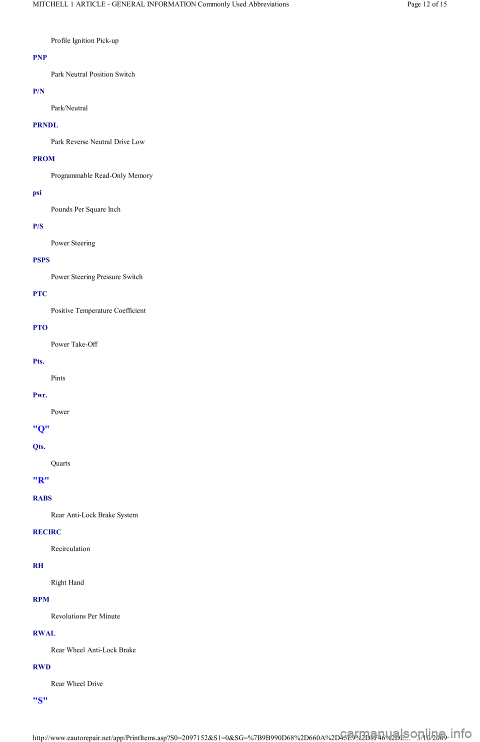
Profile Ignition Pick-up
PNP
Park Neutral Position Switch
P/N
Park/Neutral
PRNDL
Park Reverse Neutral Drive Low
PROM
Programmable Read-Only Memory
psi
Pounds Per Square Inch
P/S
Power Steering
PSPS
Power Steering Pressure Switch
PTC
Positive Temperature Coefficient
PTO
Power Take-Off
Pts.
Pints
Pwr.
Power
"Q"
Qts.
Quarts
"R"
RABS
Rear Anti-Lock Brake System
RECIRC
Recirculation
RH
Right Hand
RPM
Revolutions Per Minute
RWAL
Rear Wheel Anti-Lock Brake
RWD
Rear Wheel Drive
"S"
Page 12 of 15 MITCHELL 1 ARTICLE - GENERAL INFORMATION Commonly Used Abbreviations
3/10/2009 http://www.eautorepair.net/app/PrintItems.asp?S0=2097152&S1=0&SG=%7B9B990D68%2D660A%2D45E9%2D8F46%2DE
...