1991 FORD FESTIVA steering wheel
[x] Cancel search: steering wheelPage 301 of 454
Back To Article
GENERAL INFORMATION
Wheel Alignm ent T heory & Operation
* PLEASE READ THIS FIRST *
PRE-ALIGNMENT INSTRUCTIONS
GENERAL ALIGNMENT CHECKS
Before adjusting wheel alignment, check the following:
Each axle uses tires of same construction and tread style, equal in tread wear and overall diameter. Verify that radial and axial runout is
not excessive. Inflation should be at manufacturer's specifications.
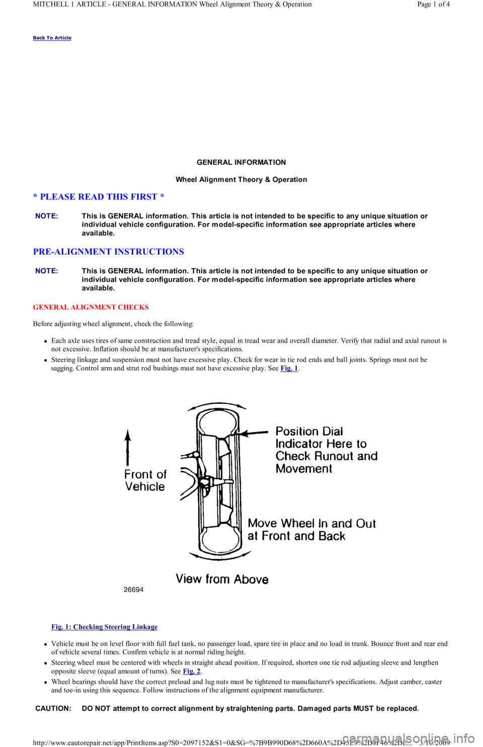
Steering linkage and suspension must not have excessive play. Check for wear in tie rod ends and ball joints. Springs must not be
sagging. Control arm and strut rod bushings must not have excessive play. See Fig. 1
.
Fig. 1: Checking Steering Linkage
Vehicle must be on level floor with full fuel tank, no passenger load, spare tire in place and no load in trunk. Bounce front and rear end
of vehicle several times. Confirm vehicle is at normal riding height.
Steering wheel must be centered with wheels in straight ahead position. If required, shorten one tie rod adjusting sleeve and lengthen
opposite sleeve (equal amount of turns). See Fig. 2
.
Wheel bearings should have the correct preload and lug nuts must be tightened to manufacturer's specifications. Adjust camber, caster
and toe-in using this sequence. Follow instructions of the alignment equipment manufacturer. NOTE:This is GENERAL inform ation. This article is not intended to be specific to any unique situation or
individual vehicle configuration. For m odel-specific inform ation see appropriate articles where
available.
NOTE:This is GENERAL inform ation. This article is not intended to be specific to any unique situation or
individual vehicle configuration. For m odel-specific inform ation see appropriate articles where
available.
CAUT ION: DO NOT attem pt to correct alignm ent by straightening parts. Dam aged parts MUST be replaced.
Page 1 of 4 MITCHELL 1 ARTICLE - GENERAL INFORMATION Wheel Alignment Theory & Operation
3/10/2009 http://www.eautorepair.net/app/PrintItems.asp?S0=2097152&S1=0&SG=%7B9B990D68%2D660A%2D45E9%2D8F46%2DE
...
Page 302 of 454
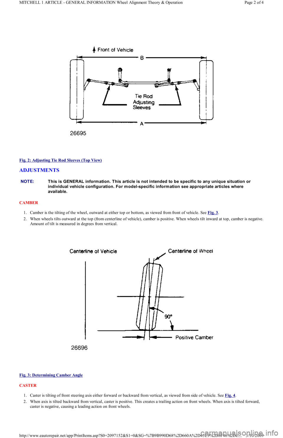
Fig. 2: Adjusting Tie Rod Sleeves (Top View)
ADJUSTMENTS
CAMBER
1. Camber is the tilting of the wheel, outward at either top or bottom, as viewed from front of vehicle. See Fig. 3
.
2. When wheels tilts outward at the top (from centerline of vehicle), camber is positive. When wheels tilt inward at top, camber is negative.
Amount of tilt is measured in degrees from vertical.
Fig. 3: Determining Camber Angle
CASTER
1. Caster is tilting of front steering axis either forward or backward from vertical, as viewed from side of vehicle. See Fig. 4
.
2. When axis is tilted backward from vertical, caster is positive. This creates a trailing action on front wheels. When axis is tilted forward,
caster is negative, causing a leading action on front wheels.
NOTE:This is GENERAL inform ation. This article is not intended to be specific to any unique situation or
individual vehicle configuration. For m odel-specific inform ation see appropriate articles where
available.
Page 2 of 4 MITCHELL 1 ARTICLE - GENERAL INFORMATION Wheel Alignment Theory & Operation
3/10/2009 http://www.eautorepair.net/app/PrintItems.asp?S0=2097152&S1=0&SG=%7B9B990D68%2D660A%2D45E9%2D8F46%2DE
...
Page 303 of 454
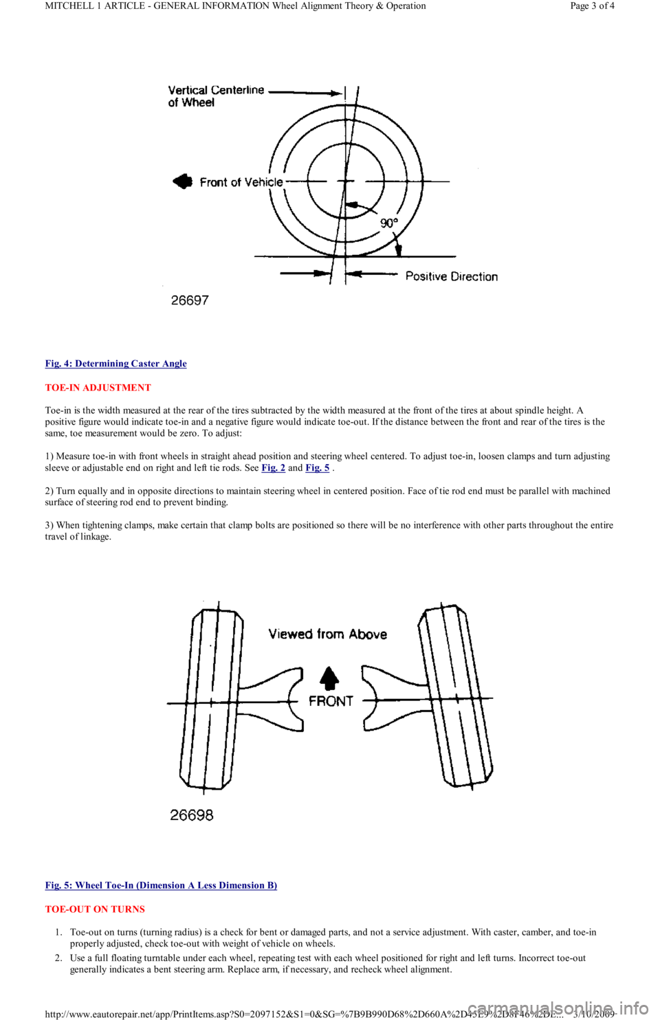
Fig. 4: Determining Caster Angle
TOE-IN ADJUSTMENT
Toe-in is the width measured at the rear of the tires subtracted by the width measured at the front of the tires at about spindle height. A
positive figure would indicate toe-in and a negative figure would indicate toe-out. If the distance between the front and rear of the tires is the
same, toe measurement would be zero. To adjust:
1) Measure toe-in with front wheels in straight ahead position and steering wheel centered. To adjust toe-in, loosen clamps and turn adjusting
sleeve or adjustable end on right and left tie rods. See Fig. 2
and Fig. 5 .
2) Turn equally and in opposite directions to maintain steering wheel in centered position. Face of tie rod end must be parallel with machined
surface of steering rod end to prevent binding.
3) When tightening clamps, make certain that clamp bolts are positioned so there will be no interference with other parts throughout the entire
travel of linkage.
Fig. 5: Wheel Toe
-In (Dimension A Less Dimension B)
TOE-OUT ON TURNS
1. Toe-out on turns (turning radius) is a check for bent or damaged parts, and not a service adjustment. With caster, camber, and toe-in
properly adjusted, check toe-out with weight of vehicle on wheels.
2. Use a full floating turntable under each wheel, repeating test with each wheel positioned for right and left turns. Incorrect toe-out
generally indicates a bent steering arm. Replace arm, if necessary, and recheck wheel alignment.
Page 3 of 4 MITCHELL 1 ARTICLE - GENERAL INFORMATION Wheel Alignment Theory & Operation
3/10/2009 http://www.eautorepair.net/app/PrintItems.asp?S0=2097152&S1=0&SG=%7B9B990D68%2D660A%2D45E9%2D8F46%2DE
...
Page 304 of 454
STEERING AXIS INCLINATION
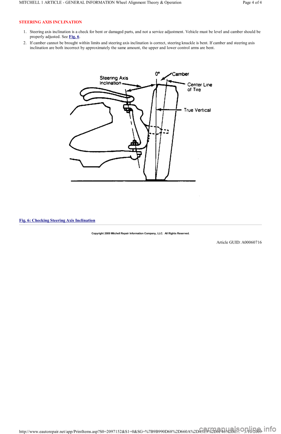
1. Steering axis inclination is a check for bent or damaged parts, and not a service adjustment. Vehicle must be level and camber should be
properly adjusted. See Fig. 6
.
2. If camber cannot be brought within limits and steering axis inclination is correct, steering knuckle is bent. If camber and steering axis
inclination are both incorrect by approximately the same amount, the upper and lower control arms are bent.
Fig. 6: Checking Steering Axis Inclination
Copyr ight 2009 Mitchell Repair Information Company, LLC. All Rights Reserved.
Article GUID: A00060716
Page 4 of 4 MITCHELL 1 ARTICLE - GENERAL INFORMATION Wheel Alignment Theory & Operation
3/10/2009 http://www.eautorepair.net/app/PrintItems.asp?S0=2097152&S1=0&SG=%7B9B990D68%2D660A%2D45E9%2D8F46%2DE
...
Page 346 of 454
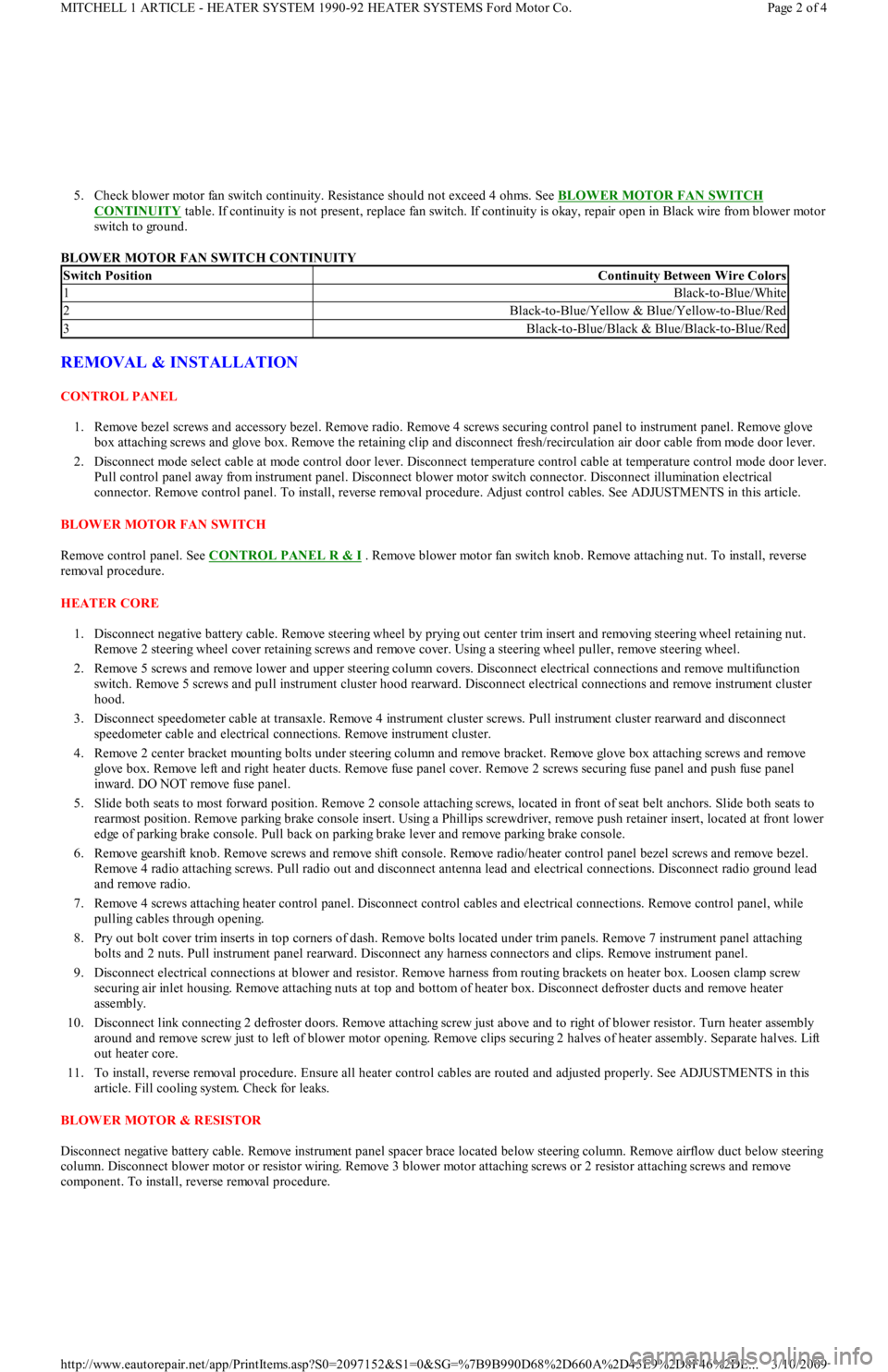
5. Check blower motor fan switch continuity. Resistance should not exceed 4 ohms. See BLOWER MOTOR FAN SWITCH
CONTINUITY table. If continuity is not present, replace fan switch. If continuity is okay, repair open in Black wire from blower motor
switch to ground.
BLOWER MOTOR FAN SWITCH CONTINUITY
REMOVAL & INSTALLATION
CONTROL PANEL
1. Remove bezel screws and accessory bezel. Remove radio. Remove 4 screws securing control panel to instrument panel. Remove glove
box attaching screws and glove box. Remove the retaining clip and disconnect fresh/recirculation air door cable from mode door lever.
2. Disconnect mode select cable at mode control door lever. Disconnect temperature control cable at temperature control mode door lever.
Pull control panel away from instrument panel. Disconnect blower motor switch connector. Disconnect illumination electrical
connector. Remove control panel. To install, reverse removal procedure. Adjust control cables. See ADJUSTMENTS in this article.
BLOWER MOTOR FAN SWITCH
Remove control panel. See CONTROL PANEL R & I
. Remove blower motor fan switch knob. Remove attaching nut. To install, reverse
removal procedure.
HEATER CORE
1. Disconnect negative battery cable. Remove steering wheel by prying out center trim insert and removing steering wheel retaining nut.
Remove 2 steering wheel cover retaining screws and remove cover. Using a steering wheel puller, remove steering wheel.
2. Remove 5 screws and remove lower and upper steering column covers. Disconnect electrical connections and remove multifunction
switch. Remove 5 screws and pull instrument cluster hood rearward. Disconnect electrical connections and remove instrument cluster
hood.
3. Disconnect speedometer cable at transaxle. Remove 4 instrument cluster screws. Pull instrument cluster rearward and disconnect
speedometer cable and electrical connections. Remove instrument cluster.
4. Remove 2 center bracket mounting bolts under steering column and remove bracket. Remove glove box attaching screws and remove
glove box. Remove left and right heater ducts. Remove fuse panel cover. Remove 2 screws securing fuse panel and push fuse panel
inward. DO NOT remove fuse panel.
5. Slide both seats to most forward position. Remove 2 console attaching screws, located in front of seat belt anchors. Slide both seats to
rearmost position. Remove parking brake console insert. Using a Phillips screwdriver, remove push retainer insert, located at front lower
edge of parking brake console. Pull back on parking brake lever and remove parking brake console.
6. Remove gearshift knob. Remove screws and remove shift console. Remove radio/heater control panel bezel screws and remove bezel.
Remove 4 radio attaching screws. Pull radio out and disconnect antenna lead and electrical connections. Disconnect radio ground lead
and remove radio.
7. Remove 4 screws attaching heater control panel. Disconnect control cables and electrical connections. Remove control panel, while
pulling cables through opening.
8. Pry out bolt cover trim inserts in top corners of dash. Remove bolts located under trim panels. Remove 7 instrument panel attaching
bolts and 2 nuts. Pull instrument panel rearward. Disconnect any harness connectors and clips. Remove instrument panel.
9. Disconnect electrical connections at blower and resistor. Remove harness from routing brackets on heater box. Loosen clamp screw
securing air inlet housing. Remove attaching nuts at top and bottom of heater box. Disconnect defroster ducts and remove heater
assembly.
10. Disconnect link connecting 2 defroster doors. Remove attaching screw just above and to right of blower resistor. Turn heater assembly
around and remove screw just to left of blower motor opening. Remove clips securing 2 halves of heater assembly. Separate halves. Lift
out heater core.
11. To install, reverse removal procedure. Ensure all heater control cables are routed and adjusted properly. See ADJUSTMENTS in this
article. Fill cooling system. Check for leaks.
BLOWER MOTOR & RESISTOR
Disconnect negative battery cable. Remove instrument panel spacer brace located below steering column. Remove airflow duct below steering
column. Disconnect blower motor or resistor wiring. Remove 3 blower motor attaching screws or 2 resistor attaching screws and remove
component. To install, reverse removal procedure.
Switch PositionContinuity Between Wire Colors
1Black-to-Blue/White
2Black-to-Blue/Yellow & Blue/Yellow-to-Blue/Red
3Black-to-Blue/Black & Blue/Black-to-Blue/Red
Page 2 of 4 MITCHELL 1 ARTICLE - HEATER SYSTEM 1990-92 HEATER SYSTEMS Ford Motor Co.
3/10/2009 http://www.eautorepair.net/app/PrintItems.asp?S0=2097152&S1=0&SG=%7B9B990D68%2D660A%2D45E9%2D8F46%2DE
...
Page 347 of 454
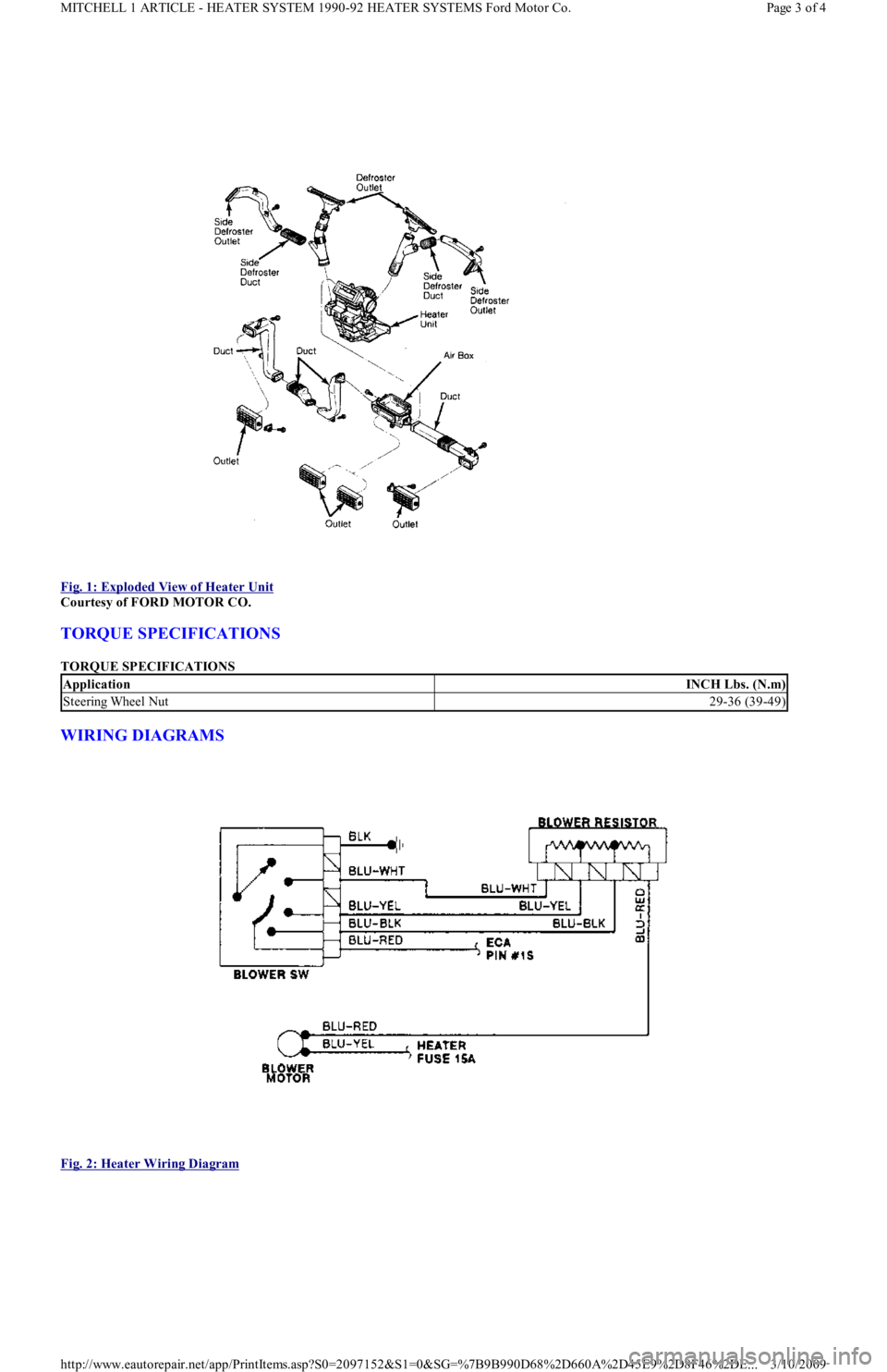
Fig. 1: Exploded View of Heater Unit
Courtesy of FORD MOTOR CO.
TORQUE SPECIFICATIONS
TORQUE SPECIFICATIONS
WIRING DIAGRAMS
Fig. 2: Heater Wiring Diagram
ApplicationINCH Lbs. (N.m)
Steering Wheel Nut29-36 (39-49)
Page 3 of 4 MITCHELL 1 ARTICLE - HEATER SYSTEM 1990-92 HEATER SYSTEMS Ford Motor Co.
3/10/2009 http://www.eautorepair.net/app/PrintItems.asp?S0=2097152&S1=0&SG=%7B9B990D68%2D660A%2D45E9%2D8F46%2DE
...
Page 361 of 454
tube from evaporator core fins while removing thermostatic switch. To install, reverse removal procedure. Evacuate and recharge system.
THERMOSTATIC EXPANSION VALVE
Removal & Installation
1. Discharge A/C system using approved refrigerant recovery/recycling equipment. Remove evaporator housing. See EVAPORATOR
HOUSING under REMOVAL & INSTALLATION. Remove air inlet duct. See Fig. 1 .
2. Remove insulation from sensing bulb. Disconnect thermostatic expansion valve at evaporator tube fitting and inlet tube fitting (from
receiver-drier). See Fig. 3
. Remove thermostatic expansion valve. To install, reverse removal procedure. Use new "O" rings. Evacuate
and recharge system.
A/C RELAYS
Removal & Installation
A/C relays are located in left front corner of engine compartment, near battery. Unclip relay holder from its mounting bracket. Disconnect
relay wiring. DO NOT pull on wiring connector to remove relay from holder. Remove relay from holder. To install, reverse removal procedure.
A/C-HEATER CONTROL ASSEMBLY
Removal & Installation
1. A/C control module is located above radio. Remove accessory bezel. Remove radio (if necessary) and glove box. Disconnect
recirculated/fresh air cable from door lever. See Fig. 5
. Disconnect mode select cable from door lever. See Fig. 6 .
2. Disconnect temperature control cable from door lever. See Fig. 4
. Pull control assembly away from dash, and disconnect wiring
connectors. Remove control assembly.
3. To install, reverse removal procedure. Check and adjust temperature control, recirculated/fresh air and mode cables. See
ADJUSTMENTS. Test control assembly operation.
BLOWER MOTOR
Removal & Installation
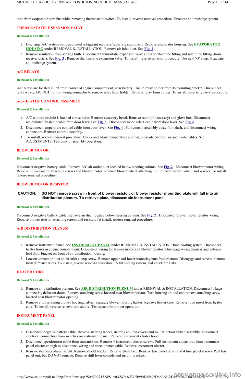
Disconnect negative battery cable. Remove A/C air outlet duct located below steering column. See Fig. 2 . Disconnect blower motor wiring.
Remove blower motor attaching screws and blower motor. Remove blower wheel attaching nut. Remove blower wheel and washer. To install,
reverse removal procedure.
BLOWER MOTOR RESISTOR
Removal & Installation
Disconnect negative battery cable. Remove air duct located below steering column. See Fig. 2 . Disconnect blower motor resistor wiring.
Remove blower resistor attaching screws and resistor. To install, reverse removal procedure.
AIR DISTRIBUTION PLENUM
Removal & Installation
1. Remove instrument panel. See INSTRUMENT PANEL under REMOVAL & INSTALLATION. Drain cooling system. Disconnect
heater hoses in engine compartment. Disconnect wiring for blower motor and blower resistor. Disengage wiring harness and antenna
lead from bracket on front of air distribution housing.
2. Loosen connector duct-to-air inlet clamp screw. Remove upper and lower mounting nuts from plenum. Disengage and remove plenum
from defroster ducts. To install, reverse removal procedure. Refill cooling system, and check for leaks.
HEATER CORE
Removal & Installation
1. Remove air distribution plenum. See AIR DISTRIBUTION PLENUM under REMOVAL & INSTALLATION. Disconnect linkage
connecting defroster doors. Remove attaching screw located near blower resistor. Turn housing around and remove attaching screw
located near blower motor opening.
2. Remove clips retaining blower housing halves. Separate blower housing halves. Remove heater core. Remove tube insert from heater
core. To install, reverse removal procedure. Test system for proper operation.
INSTRUMENT PANEL
Removal & Installation
1. Disconnect negative battery cable. Remove steering wheel, steering column covers and multifunction switch assembly. Disconnect
electrical connectors from switches on instrument panel. Remove instrument cluster hood.
2. Disconnect speedometer cable from transmission. Remove 4 instrument cluster screws. Pull instrument cluster out from instrument
panel cluster enough to disconnect wiring and speedometer cable. Remove instrument cluster.
3. Remove steering column shield. Remove shield bracket. Remove glove box. Remove fuse panel cover and 4 fuse panel screws. Pull fu se
panel out, but DO NOT remove. Remove shift lever console and mount brackets. CAUTION: DO NOT rem ove screw in front of blower resistor, or blower resistor m ounting plate will fall into air
distribution plenum . T o retrieve plate, disassem ble instrum ent panel.
Page 13 of 14 MITCHELL 1 ARTICLE - 1991 AIR CONDITIONING & HEAT MANUAL A/C
3/10/2009 http://www.eautorepair.net/app/PrintItems.asp?S0=2097152&S1=0&SG=%7B9B990D68%2D660A%2D45E9%2D8F46%2DE
...
Page 375 of 454
Back To Article
ST EERING SYST EM - MANUAL
1991 ST EERING Ford Motor Co. - Steering - Manual Rack & Pinion
DESCRIPTION
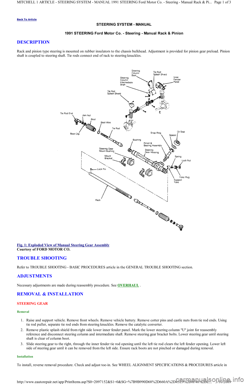
Rack and pinion type steering is mounted on rubber insulators to the chassis bulkhead. Adjustment is provided for pinion gear preload. Pinion
shaft is coupled to steering shaft. Tie rods connect end of rack to steering knuckles.
Fig. 1: Exploded View of Manual Steering Gear Assembly
Courtesy of FORD MOTOR CO.
TROUBLE SHOOTING
Refer to TROUBLE SHOOTING - BASIC PROCEDURES article in the GENERAL TROUBLE SHOOTING section.
ADJUSTMENTS
Necessary adjustments are made during reassembly procedure. See OVERHAUL .
REMOVAL & INSTALLATION
STEERING GEAR
Removal
1. Raise and support vehicle. Remove front wheels. Remove vehicle battery. Remove cotter pins and castle nuts from tie rod ends. Using
tie rod puller, separate tie rod ends from steering knuckles. Remove the catalytic converter.
2. Remove plastic splash shield from right side lower inner fender panel. Mark the lower steering column "U" joint for reassembly
reference and disconnect steering column and intermediate shaft. Remove steering gear bracket bolts. Lower steering gear until steering
shaft is clear of column boot.
3. Slide steering gear to the right, through the inner fender tie rod opening until the left tie rod clears the left fender opening. Lower left
side of steering gear until it can be removed from the left side. Ensure rack boots are not pinched or damaged during removal.
Installation
To install, reverse removal procedure. Check and adjust toe-in. See WHEEL ALIGNMENT SPECIFICATIONS & PROCEDURES article in
Page 1 of 3 MITCHELL 1 ARTICLE - STEERING SYSTEM - MANUAL 1991 STEERING Ford Motor Co. - Steering - Manual Rack & Pi
...
3/10/2009 http://www.eautorepair.net/app/PrintItems.asp?S0=2097152&S1=0&SG=%7B9B990D68%2D660A%2D45E9%2D8F46%2DE
...