1991 FORD FESTIVA bolt pattern
[x] Cancel search: bolt patternPage 241 of 454

A "howling" or "whining" noise from the ring and pinion gear can be caused by an improper gear pattern, gear damage, or improper bearing
preload. It can occur at various speeds and driving conditions, or it can be continuous.
Before disassembling axle to diagnose and correct gear ke sure that tires, exhaust, and vehicle trim have been checked as possible causes.
Chuckle
This is a particular rattling noise that sounds like a stick against the spokes of a spinning bicycle wheel. It occurs while decelerating from 40
MPH and usually can be heard until vehicle comes to a complete stop. The frequency varies with the speed of the vehicle.
A chuckle that occurs on the driving phase is usually caused ive clearance due to differential gear wear, or by a damaged tooth on the coast
side of the pinion or ring gear. Even a very small tooth nick or a ridge on the edge of a gear tooth is enough the cause the noise.
This condition can be corrected simply by cleaning the gear tooth nick or ridge with a small grinding wheel. If either gear is damaged or scored
badly, the gear set must be replaced. If metal has broken loose, the carrier and housing must be cleaned to remove particles that could cause
damage.
Knock
This is very similar to a chuckle, though it may be louder, and occur on acceleration or deceleration. Knock can be caused by a gear tooth that
is damaged on the drive side of the ring and pinion gears. Ring gear bolts that are hitting the carrier casting can cause knock. Knock can also be
due to excessive end play in the axle shafts.
Clunk
Clunk is a metallic noise heard when an automatic transmission is engaged in Reverse or Drive, or when throttle is applied or released. It is
caused by backlash somewhere in the driveline, but not necessarily in the axle. To determine whether driveline clunk is caused by the axle,
check the total axle backlash as follows:
1. Raise vehicle on a frame or twinpost hoist so that drive wheels are free. Clamp a bar between axle companion flange and a part of the
frame or body so that flange cannot move.
2. On conventional drive axles, lock the left wheel to keep it from turning. On all models, turn the right wheel slowly until it is felt to be in
Drive condition. Hold a chalk marker on side of tire about 12" from center of wheel. Turn wheel in the opposite direction until it is
again felt to be in Drive condition.
3. Measure the length of the chalk mark, which is the total axle backlash. If backlash is one inch or less, drive axle is not the source of
clunk noise.
Bearing Whine
Bearing whine is a high-pitched sound similar to a whistle. It is usually caused by malfunctioning pinion bearings. Pinion bearings operate at
drive shaft speed. Roller wheel bearings may whine in a similar manner if they run completely dry of lubricant. Bearing noise will occur at all
driving speeds. This distinguishes it from gear whine, which usually comes and goes as speed changes.
Bearing Rumble
Bearing rumble sounds like marbles being tumbled. It is usually caused by a malfunctioning wheel bearing. The lower pitch is because the
wheel bearing turns at only about 1/3 of drive shaft speed.
Chatter On Turns
This is a condition where the entire front or rear of vehicle vibrates when vehicle is moving. The vibration is plainly felt as well as heard. Extra
differential thrust washers installed during axle repair can cause a condition of partial lock-up that creates this chatter.
Axle Shaft Noise
Axle shaft noise is similar to gear noise and pinion bearing whine. Axle shaft bearing noise will normally distinguish itself from gear noise by
occurring in all driving modes (Drive, cruise, coast and float), and will persist with transmission in Neutral while vehicle is moving at problem
speed.
If vehicle displays this noise condition, remove suspect parts, replace wheel seals and install a new set of bearings. Re-evaluate vehicle for
noise before removing any internal components.
Vibration
Vibration is a high-frequency trembling, shaking or grinding condition (felt or heard) that may be constant or variable in level and can occur
during the total operating speed range of the vehicle.
The types of vibrations that can be felt in the vehicle can d into 3 main groups:
Vibrations of various unbalanced rotating parts of the vehicle.
Resonance vibrations of the body and frame structures caused by rotating of unbalanced parts.
Tip-in moans of resonance vibrations from stressed engine or exhaust system mounts or driveline flexing modes.
DRIVE AXLE - RWD TROUBLE SHOOTING
NOTE:This is GENERAL inform ation. This article is not intended to be specific to any unique situation or
individual vehicle configuration. T he purpose of this T rouble Shooting inform ation is to provide a list
of com m on causes to problem sym ptom s. For m odel-specific T rouble Shooting, refer to SUBJECT ,
DIAGNOST IC, or T EST ING articles available in the section(s) you are accessing. For definitions of listed
noises or sounds, see DRIVE AXLE
- NOISE DIAGNOSIS under POWERTRAIN.
Page 28 of 36 MITCHELL 1 ARTICLE - GENERAL INFORMATION Trouble Shooting - Basic Procedures
3/10/2009 http://www.eautorepair.net/app/PrintItems.asp?S0=2097152&S1=0&SG=%7B9B990D68%2D660A%2D45E9%2D8F46%2DE
...
Page 253 of 454

Back To Article
GENERAL INFORMATION
Drive Axle Noise Diagnosis
* PLEASE READ THIS FIRST *
UNRELATED NOISES
Some driveline trouble symptoms are also common to the engine, transmission, wheel bearings, tires and other parts of the vehicle. Make sure
that cause of trouble actually is in the drive axle before adjusting, repairing, or replacing any parts.
NON-DRIVE AXLE NOISES
A few conditions can sound just like drive axle noise and have to be considered in pre-diagnosis. The 4 most common noises are exhaust, tires,
CV/universal joints and trim moldings.
In certain conditions, the pitch of exhaust gases may sound like gear whine. At other times, it may be mistaken for a wheel bearing rumble.
Tires, especially radial and snow tires, can have a high-pitched tread whine or roar, similar to gear noise. Also, some non-standard tires with an
unusual tread construction may emit a roar or whine.
Defective CV/universal joints may cause clicking noises or excessive driveline play that can be improperly diagnosed as drive axle problems.
Trim and moldings can also cause a whistling or whining noise. Ensure that none of these components are causing the noise before
disassembling the drive axle.
GEAR NOISE
A "howling" or "whining" noise from the ring and pinion gear can be caused by an improper gear pattern, gear damage, or improper bearing
preload. It can occur at various speeds and driving conditions, or it can be continuous.
Before disassembling axle to diagnose and correct gear noise, make sure that tires, exhaust, and vehicle trim have been checked as possible
causes.
CHUCKLE
This is a particular rattling noise that sounds like a stick against the spokes of a spinning bicycle wheel. It occurs while decelerating from 40
MPH and usually can be heard until vehicle comes to a complete stop. The frequency varies with the speed of the vehicle.
A chuckle that occurs on the driving phase is usually caused by excessive clearance due to differential gear wear, or by a damaged tooth on the
coast side of the pinion or ring gear. Even a very small tooth nick or a ridge on the edge of a gear tooth is enough to cause the noise.
This condition can be corrected simply by cleaning the gear tooth nick or ridge with a small grinding wheel. If either gear is damaged or scored
badly, the gear set must be replaced. If metal has broken loose, the carrier and housing must be cleaned to remove particles that could cause
damage.
KNOCK
This is very similar to a chuckle, though it may be louder, and occur on acceleration of deceleration. Knock can be caused by a gear tooth that
is damaged on the drive side of the ring and pinion gears. Ring gear bolts that are hitting the carrier casting can cause knock. Knock can also be
due to excessive end play in the axle shafts. NOTE:This is GENERAL inform ation. This article is not intended to be specific to any unique situation or
individual vehicle configuration. For m odel-specific inform ation see appropriate articles where
available.
NOTE:This is GENERAL inform ation. This article is not intended to be specific to any unique situation or
individual vehicle configuration. For m odel-specific inform ation see appropriate articles where
available.
NOTE:This is GENERAL inform ation. This article is not intended to be specific to any unique situation or
individual vehicle configuration. For m odel-specific inform ation see appropriate articles where
available.
NOTE:This is GENERAL inform ation. This article is not intended to be specific to any unique situation or
individual vehicle configuration. For m odel-specific inform ation see appropriate articles where
available.
NOTE:This is GENERAL inform ation. This article is not intended to be specific to any unique situation or
individual vehicle configuration. For m odel-specific inform ation see appropriate articles where
available.
NOTE:This is GENERAL inform ation. This article is not intended to be specific to any unique situation or
individual vehicle configuration. For m odel-specific inform ation see appropriate articles where
available.
Page 1 of 2 MITCHELL 1 ARTICLE - GENERAL INFORMATION Drive Axle Noise Diagnosis
3/10/2009 http://www.eautorepair.net/app/PrintItems.asp?S0=2097152&S1=0&SG=%7B9B990D68%2D660A%2D45E9%2D8F46%2DE
...
Page 311 of 454

Fig. 1: Exploded View of Chrysler, Ford & Nippondenso 6-Cyl Compressors
Courtesy of FORD MOTOR CO.
Installation
1. Place dowel pins in compressor. Lubricate inlet reed valve with refrigerant oil. Install inlet reed valve on compressor. Install front valve
plate assembly on compressor.
2. Lubricate shaft seal seat with refrigerant oil. Position Seat Installer (T81P-19623-C) on new seat so installer is placed on raised side of
seat. Install shaft seal seat.
3. Install shaft seal assembly in front head so sealing surface is toward en of compressor shaft. Ensure flat areas on shaft seal assembly
engage with flat areas on compressor shaft.
4. Lubricate front head "O" ring with refrigerant oil. Install front head and "O" ring. Tighten retaining bolts in a crisscross pattern to 19 ft.
lbs. (26 N.m). DO NOT use air tools to tighten retaining bolts.
5. Install clutch assembly. Add same amount new refrigerant oil to compressor as was drained. Install compressor. Evacuate and recharge
system. Perform leak test.
FORD FX-15 10-CYL CLUTCH ASSEMBLY
Removal
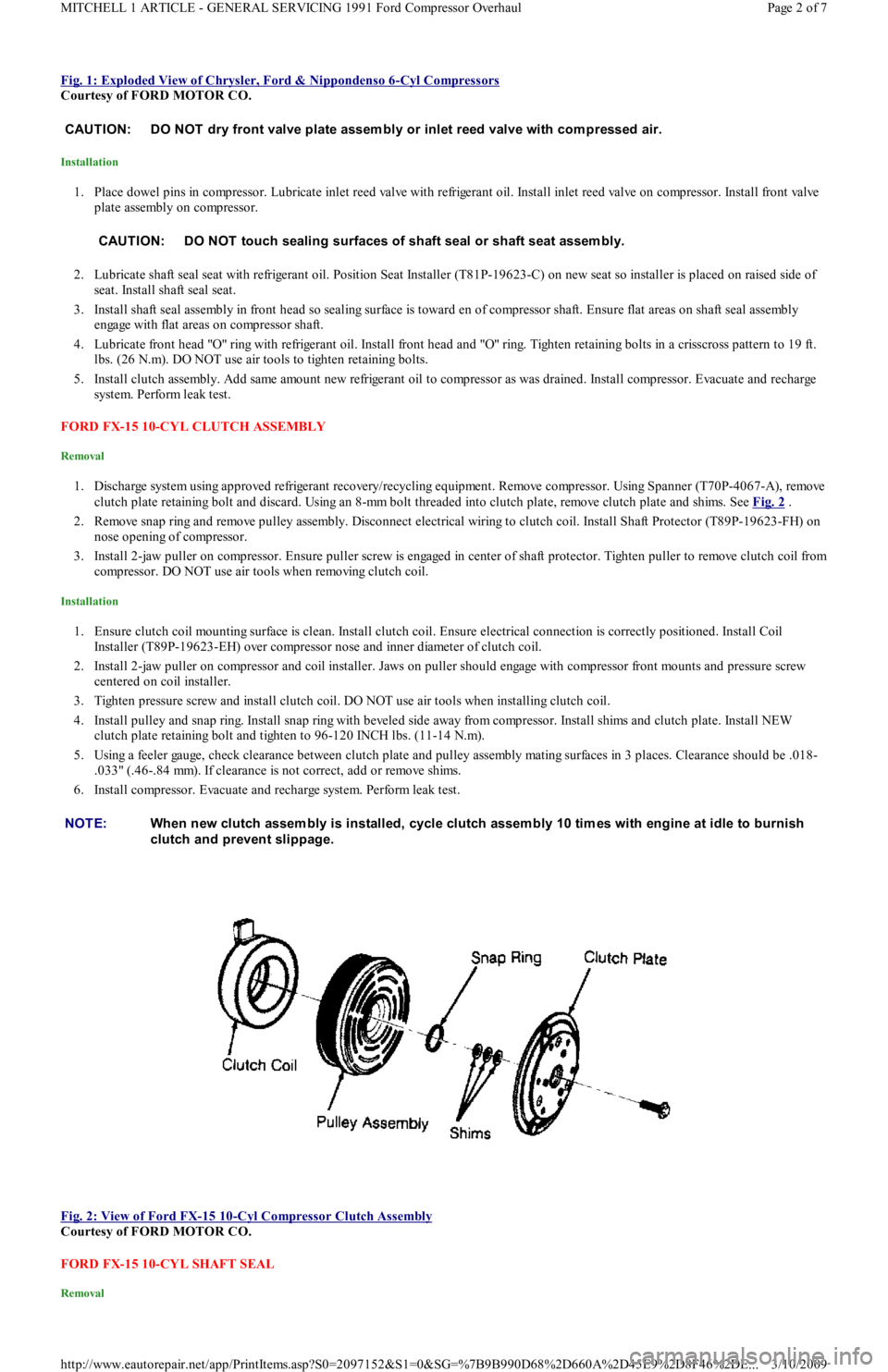
1. Discharge system using approved refrigerant recovery/recycling equipment. Remove compressor. Using Spanner (T70P-4067-A), remove
clutch plate retaining bolt and discard. Using an 8-mm bolt threaded into clutch plate, remove clutch plate and shims. See Fig. 2
.
2. Remove snap ring and remove pulley assembly. Disconnect electrical wiring to clutch coil. Install Shaft Protector (T89P-19623-FH) on
nose opening of compressor.
3. Install 2-jaw puller on compressor. Ensure puller screw is engaged in center of shaft protector. Tighten puller to remove clutch coil from
compressor. DO NOT use air tools when removing clutch coil.
Installation
1. Ensure clutch coil mounting surface is clean. Install clutch coil. Ensure electrical connection is correctly positioned. Install Coil
Installer (T89P-19623-EH) over compressor nose and inner diameter of clutch coil.
2. Install 2-jaw puller on compressor and coil installer. Jaws on puller should engage with compressor front mounts and pressure screw
centered on coil installer.
3. Tighten pressure screw and install clutch coil. DO NOT use air tools when installing clutch coil.
4. Install pulley and snap ring. Install snap ring with beveled side away from compressor. Install shims and clutch plate. Install NEW
clutch plate retaining bolt and tighten to 96-120 INCH lbs. (11-14 N.m).
5. Using a feeler gauge, check clearance between clutch plate and pulley assembly mating surfaces in 3 places. Clearance should be .018-
.033" (.46-.84 mm). If clearance is not correct, add or remove shims.
6. Install compressor. Evacuate and recharge system. Perform leak test.
Fig. 2: View of Ford FX
-15 10-Cyl Compressor Clutch Assembly
Courtesy of FORD MOTOR CO.
FORD FX-15 10-CYL SHAFT SEAL
Removal
CAUT ION: DO NOT dry front valve plate assem bly or inlet reed valve with com pressed air.
CAUT ION: DO NOT touch sealing surfaces of shaft seal or shaft seat assem bly.
NOTE:When new clutch assem bly is installed, cycle clutch assem bly 10 tim es with engine at idle to burnish
clutch and prevent slippage.
Page 2 of 7 MITCHELL 1 ARTICLE - GENERAL SERVICING 1991 Ford Compressor Overhaul
3/10/2009 http://www.eautorepair.net/app/PrintItems.asp?S0=2097152&S1=0&SG=%7B9B990D68%2D660A%2D45E9%2D8F46%2DE
...
Page 312 of 454

1. Discharge system using approved refrigerant recovery/recycling equipment and remove compressor. Using Spanner (T70P-4067-A),
remove clutch plate retaining bolt and discard. Using an 8-mm bolt threaded into clutch plate, remove clutch plate and shims. See Fig.
2 .
2. Remove shaft felt seal. Thoroughly clean seal area of compressor. Using snap ring pliers, remove shaft seal retaining snap ring.
3. Position Shaft Seal Remover (T89P-19623-BH) over compressor shaft. Push shaft seal remover downward against seal. Ensure end of
shaft seal remover is engaged with inside of seal.
4. Rotate shaft seal remover handle clockwise to expand remover tip inside seal. Pull shaft seal from compressor.
Installation
1. Shaft seal protector is included with replacement seal kit. Lubricate shaft seal protector and shaft seal with refrigerant oil.
2. Install shaft seal on shaft seal protector so lip of seal is toward compressor (large end of shaft seal protector). Install shaft seal protector
on compressor shaft.
3. Using Shaft Seal Installer (T89P-19623-AH), push shaft seal down shaft seal protector until seated. Remove shaft seal installer and
protector. Install NEW shaft seal retaining snap ring.
4. Install NEW shaft seal felt. Install clutch plate. Install new clutch plate retaining bolt and tighten to 96-120 INCH lbs. (11-14 N.m).
5. Using feeler gauge, check clearance between clutch plate and pulley assembly mating surfaces in 3 places. Clearance should be .018-
.033" (.46-.84 mm). If clearance is not correct, add or remove shims.
6. Install compressor. Evacuate and recharge system. Perform leak test.
NIPPONDENSO 6E-171 & 6P-148 CLUTCH ASSEMBLY
Removal
1. Using Spanner (T81P-19623-MH), hold clutch plate and remove crankshaft nut. Using Clutch Plate Remover (T80L-19703-B), pull
clutch plate from compressor. Remove clutch plate shims.
2. Remove snap ring and clutch pulley assembly. If pulley assembly cannot be removed by hand, use Shaft Protector (T80L-19703-G) and
3-jaw puller to remove pulley. Remove snap ring. Disconnect electrical wiring and remove clutch coil.
Installation
1. Install clutch coil over locating pin and install snap ring. Connect electrical wiring.
2. Using Pulley Installer (T80L-19703-J) and hammer (if necessary), install pulley assembly. Install snap ring with beveled side away from
compressor.
3. Install clutch plate shims. Ensure clutch plate aligns with crankshaft key. Using Clutch Plate Installer (T80L-19703-F), install clutch
plate.
4. Install crankshaft nut. Using spanner, tighten nut to 10-14 ft. lbs. (13-20 N.m). DO NOT tighten nut with air tools. Using feeler gauge,
check clearance between clutch plate and pulley.
5. Rotate compressor clutch and check clearance in more than one place. Proper clearance is .021-.035" (.53-.89 mm). If clearance is not
correct, add or remove shims.
NIPPONDENSO 6E-171 & 6P-148 SHAFT SEAL
Removal
1. Discharge system using approved refrigerant recovery/recycling equipment and remove compressor. Drain oil from suction port on
compressor and record amount for reassembly.
2. Remove clutch assembly. See NIPPONDENSO 6E-171 & 6P-148 CLUTCH ASSEMBLY R & I in this article. Ensure outer surface of
compressor is clean. Attach compressor on Clamp & Holding Fixture (T81P-19623-LH). Place fixture in vise.
3. Using Key Remover (T81P-19623-NH), remove key from compressor shaft. Remove front head-to-compressor retaining bolts and front
head. Front valve plate assembly, inlet reed valve and shaft seal assembly come off with front head. See Fig. 1
.
4. Remove dowel pins from front head. Lift inlet reed valve assembly from front head. Using Valve Plate Remover (T81P-19623-PH),
remove front valve plate assembly from front head. Remove shaft seal assembly and felt seal from front head.
5. Place front head on cardboard. Drive shaft seal seat from front head using hammer and Shaft Seal Seat Remover (T81P-19623-OH).
Clean components with solvent.
Installation
1. Place dowel pins in compressor. Lubricate inlet reed valve with refrigerant oil. Install inlet reed valve on compressor. Install front valve
plate assembly on compressor.
2. Lubricate shaft seal seat with refrigerant oil. Install Seat Installer (T81P-19623-C) on new seat so installer is placed on grooved side of
seat. Install shaft seal seat.
3. Install shaft seal assembly in front head so sealing surface is toward end of compressor shaft. Ensure flat areas on shaft seal assembly
engage with flat areas on compressor shaft.
4. Lubricate front head "O" ring with refrigerant oil. Install front head and "O" ring. Tighten retaining bolts in a crisscross pattern to 19 ft.
lbs. (26 N.m). DO NOT use air tools to tighten retaining bolts.
5. Install clutch assembly. Add same amount new refrigerant oil to compressor as was drained. Rotate compressor 10 revolutions to
distribute oil. Install compressor. Evacuate and recharge system. Perform leak test. NOTE:Rem ove com pressor when clearance is not adequate for clutch assem bly rem oval.
CAUT ION: DO NOT dry front valve plate assem bly or inlet reed valve with com pressed air.
CAUT ION: DO NOT touch sealing surfaces of shaft seal assem bly or shaft seat assem bly.
Page 3 of 7 MITCHELL 1 ARTICLE - GENERAL SERVICING 1991 Ford Compressor Overhaul
3/10/2009 http://www.eautorepair.net/app/PrintItems.asp?S0=2097152&S1=0&SG=%7B9B990D68%2D660A%2D45E9%2D8F46%2DE
...