1991 FORD FESTIVA wheel size
[x] Cancel search: wheel sizePage 220 of 454
BRAKES
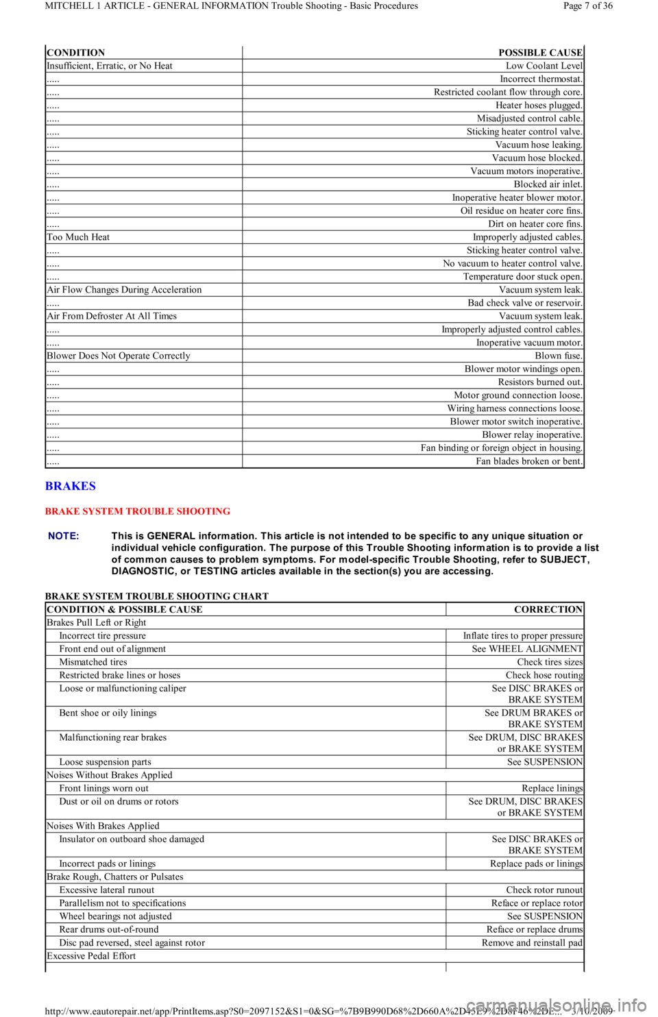
BRAKE SYSTEM TROUBLE SHOOTING
BRAKE SYSTEM TROUBLE SHOOTING CHART
CONDITIONPOSSIBLE CAUSE
Insufficient, Erratic, or No HeatLow Coolant Level
.....Incorrect thermostat.
.....Restricted coolant flow through core.
.....Heater hoses plugged.
.....Misadjusted control cable.
.....Sticking heater control valve.
.....Vacuum hose leaking.
.....Vacuum hose blocked.
.....Vacuum motors inoperative.
.....Blocked air inlet.
.....Inoperative heater blower motor.
.....Oil residue on heater core fins.
.....Dirt on heater core fins.
Too Much HeatImproperly adjusted cables.
.....Sticking heater control valve.
.....No vacuum to heater control valve.
.....Temperature door stuck open.
Air Flow Changes During AccelerationVacuum system leak.
.....Bad check valve or reservoir.
Air From Defroster At All TimesVacuum system leak.
.....Improperly adjusted control cables.
.....Inoperative vacuum motor.
Blower Does Not Operate CorrectlyBlown fuse.
.....Blower motor windings open.
.....Resistors burned out.
.....Motor ground connection loose.
.....Wiring harness connections loose.
.....Blower motor switch inoperative.
.....Blower relay inoperative.
.....Fan binding or foreign object in housing.
.....Fan blades broken or bent.
NOTE:This is GENERAL inform ation. This article is not intended to be specific to any unique situation or
individual vehicle configuration. T he purpose of this T rouble Shooting inform ation is to provide a list
of com m on causes to problem sym ptom s. For m odel-specific T rouble Shooting, refer to SUBJECT ,
DIAGNOST IC, or T EST ING articles available in the section(s) you are accessing.
CONDITION & POSSIBLE CAUSECORRECTION
Brakes Pull Left or Right
Incorrect tire pressureInflate tires to proper pressure
Front end out of alignmentSee WHEEL ALIGNMENT
Mismatched tiresCheck tires sizes
Restricted brake lines or hosesCheck hose routing
Loose or malfunctioning caliperSee DISC BRAKES or
BRAKE SYSTEM
Bent shoe or oily liningsSee DRUM BRAKES or
BRAKE SYSTEM
Malfunctioning rear brakesSee DRUM, DISC BRAKES
or BRAKE SYSTEM
Loose suspension partsSee SUSPENSION
Noises Without Brakes Applied
Front linings worn outReplace linings
Dust or oil on drums or rotorsSee DRUM, DISC BRAKES
or BRAKE SYSTEM
Noises With Brakes Applied
Insulator on outboard shoe damagedSee DISC BRAKES or
BRAKE SYSTEM
Incorrect pads or liningsReplace pads or linings
Brake Rough, Chatters or Pulsates
Excessive lateral runoutCheck rotor runout
Parallelism not to specificationsReface or replace rotor
Wheel bearings not adjustedSee SUSPENSION
Rear drums out-of-roundReface or replace drums
Disc pad reversed, steel against rotorRemove and reinstall pad
Excessive Pedal Effort
Page 7 of 36 MITCHELL 1 ARTICLE - GENERAL INFORMATION Trouble Shooting - Basic Procedures
3/10/2009 http://www.eautorepair.net/app/PrintItems.asp?S0=2097152&S1=0&SG=%7B9B990D68%2D660A%2D45E9%2D8F46%2DE
...
Page 243 of 454
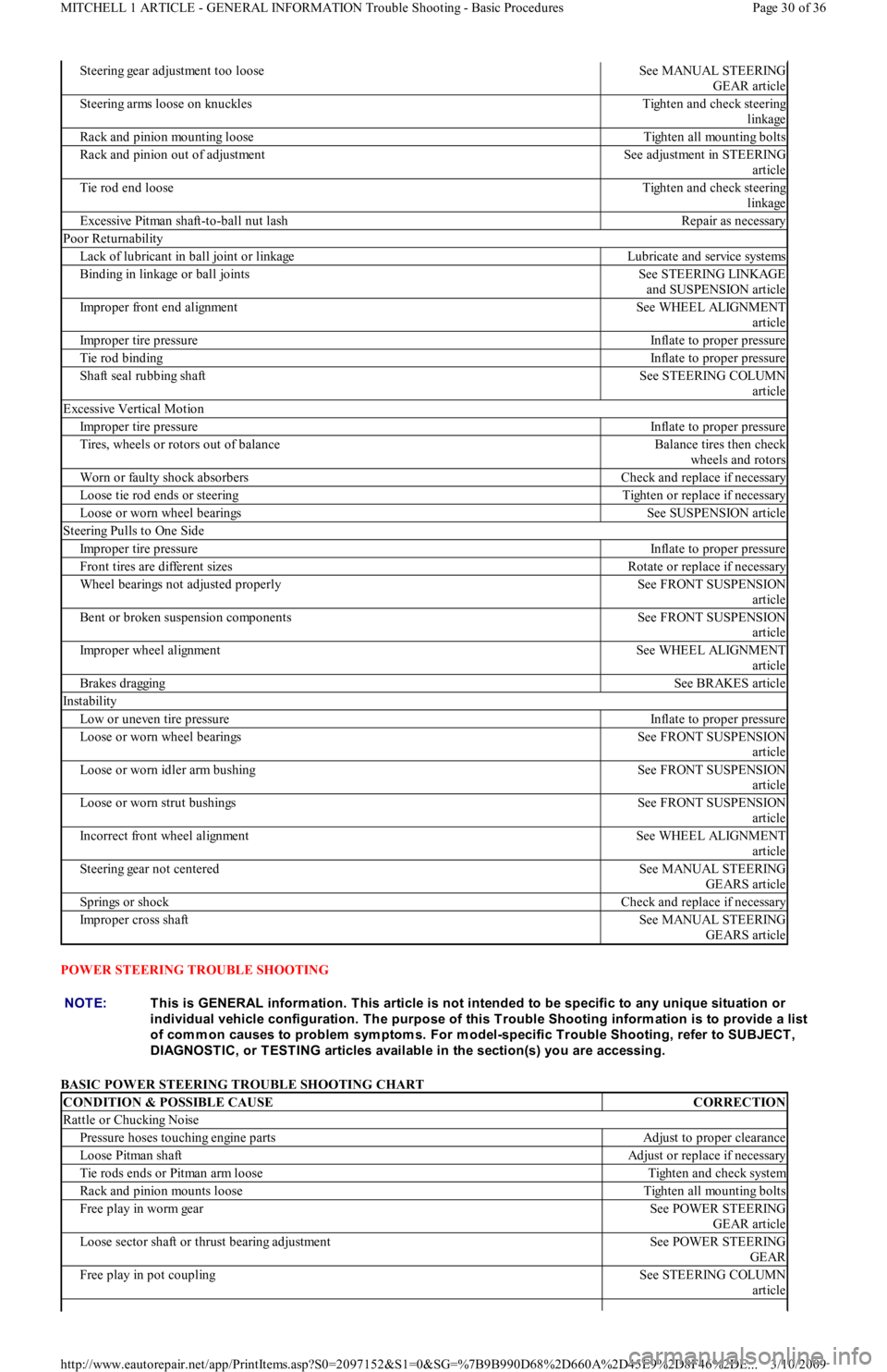
POWER STEERING TROUBLE SHOOTING
BASIC POWER STEERING TROUBLE SHOOTING CHART
Steering gear adjustment too looseSee MANUAL STEERING
GEAR article
Steering arms loose on knucklesTighten and check steering
linkage
Rack and pinion mounting looseTighten all mounting bolts
Rack and pinion out of adjustmentSee adjustment in STEERING
article
Tie rod end looseTighten and check steering
linkage
Excessive Pitman shaft-to-ball nut lashRepair as necessary
Poor Returnability
Lack of lubricant in ball joint or linkageLubricate and service systems
Binding in linkage or ball jointsSee STEERING LINKAGE
and SUSPENSION article
Improper front end alignmentSee WHEEL ALIGNMENT
article
Improper tire pressureInflate to proper pressure
Tie rod bindingInflate to proper pressure
Shaft seal rubbing shaftSee STEERING COLUMN
article
Excessive Vertical Motion
Improper tire pressureInflate to proper pressure
Tires, wheels or rotors out of balanceBalance tires then check
wheels and rotors
Worn or faulty shock absorbersCheck and replace if necessary
Loose tie rod ends or steeringTighten or replace if necessary
Loose or worn wheel bearingsSee SUSPENSION article
Steering Pulls to One Side
Improper tire pressureInflate to proper pressure
Front tires are different sizesRotate or replace if necessary
Wheel bearings not adjusted properlySee FRONT SUSPENSION
article
Bent or broken suspension componentsSee FRONT SUSPENSION
article
Improper wheel alignmentSee WHEEL ALIGNMENT
article
Brakes draggingSee BRAKES article
Instability
Low or uneven tire pressureInflate to proper pressure
Loose or worn wheel bearingsSee FRONT SUSPENSION
article
Loose or worn idler arm bushingSee FRONT SUSPENSION
article
Loose or worn strut bushingsSee FRONT SUSPENSION
article
Incorrect front wheel alignmentSee WHEEL ALIGNMENT
article
Steering gear not centeredSee MANUAL STEERING
GEARS article
Springs or shockCheck and replace if necessary
Improper cross shaftSee MANUAL STEERING
GEARS article
NOTE:This is GENERAL inform ation. This article is not intended to be specific to any unique situation or
individual vehicle configuration. T he purpose of this T rouble Shooting inform ation is to provide a list
of com m on causes to problem sym ptom s. For m odel-specific T rouble Shooting, refer to SUBJECT ,
DIAGNOST IC, or T EST ING articles available in the section(s) you are accessing.
CONDITION & POSSIBLE CAUSECORRECTION
Rattle or Chucking Noise
Pressure hoses touching engine partsAdjust to proper clearance
Loose Pitman shaftAdjust or replace if necessary
Tie rods ends or Pitman arm looseTighten and check system
Rack and pinion mounts looseTighten all mounting bolts
Free play in worm gearSee POWER STEERING
GEAR article
Loose sector shaft or thrust bearing adjustmentSee POWER STEERING
GEAR
Free play in pot couplingSee STEERING COLUMN
article
Page 30 of 36 MITCHELL 1 ARTICLE - GENERAL INFORMATION Trouble Shooting - Basic Procedures
3/10/2009 http://www.eautorepair.net/app/PrintItems.asp?S0=2097152&S1=0&SG=%7B9B990D68%2D660A%2D45E9%2D8F46%2DE
...
Page 305 of 454
Back To Article
GENERAL INFORMATION
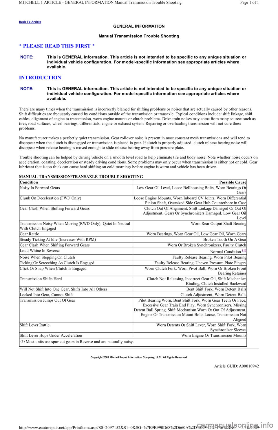
Manual Transmission Trouble Shooting
* PLEASE READ THIS FIRST *
INTRODUCTION
There are many times when the transmission is incorrectly blamed for shifting problems or noises that are actually caused by other reasons.
Shift difficulties are frequently caused by conditions outside of the transmission or transaxle. Typical conditions include: shift linkage, shift
cables, alignment of engine to transmission, worn engine mounts or clutch problems. Drive train noises may come from many sources such as
tires, road surfaces, wheel bearings, differentials, engine or exhaust system. Repairing or overhauling transmission will not cure these
problems.
No manufacturer makes a perfectly quiet transmission. Gear rollover noise is present in most constant mesh transmissions and will tend to
disappear when the clutch is disengaged or transmission is placed in gear. If clutch is properly adjusted, clutch release bearing noise will
disappear when release bearing is moved enough to slide release bearing away from pressure plate.
Trouble shooting can be helped by driving vehicle on a smooth level road to help eliminate tire and body noise. Note whether noise occurs on
acceleration, coasting, deceleration or steady driving conditions. Some problems may only occur when transmission is either hot or cold. Gear
lubricant that is too thick can cause hard shifting on cold mornings before engine is warm and vehicle has been driven.
MANUAL TRANSMISSION/TRANSAXLE TROUBLE SHOOTING NOTE:This is GENERAL inform ation. This article is not intended to be specific to any unique situation or
individual vehicle configuration. For m odel-specific inform ation see appropriate articles where
available.
NOTE:This is GENERAL inform ation. This article is not intended to be specific to any unique situation or
individual vehicle configuration. For m odel-specific inform ation see appropriate articles where
available.
ConditionPossible Cause
Noisy In Forward GearsLow Gear Oil Level, Loose Bellhousing Bolts, Worn Bearings Or
Gears
Clunk On Deceleration (FWD Only)Loose Engine Mounts, Worn Inboard CV Joints, Worn Differential
Pinion Shaft, Oversized Side Gear Hub Counterbore in Case
Gear Clash When Shifting Forward GearsClutch Out Of Alignment, Shift Linkage Damaged Or Out Of
Adjustment, Gears Or Synchronizers Damaged, Low Gear Oil
Level
Transmission Noisy When Moving (RWD Only); Quiet In Neutral
With Clutch EngagedWorn Rear Output Shaft Bearing
Gear RattleWorn Bearings, Worn Gear Oil, Low Gear Oil, Worn Gears
Steady Ticking At Idle (Increases With RPM)Broken Tooth On A Gear
Gear Clash When Shifting Forward GearsWorn Or Broken Synchronizers, Faulty Clutch
Loud Whine In ReverseNormal Condition (1)
Noise When Stepping On ClutchFaulty Release Bearing, Worn Pilot Bearing
Ticking Or Screeching As Clutch Is EngagedFaulty Release Bearing, Uneven Pressure Plate Fingers
Click Or Snap When Clutch Is EngagedWorn Clutch Fork, Worn Pivot Ball, Worn Or Broken Front
Bearing Retainer
Transmission Shifts HardClutch Not Releasing, Incorrect Gear Oil, Shift Mechanism
Binding, Clutch Installed Backward
Will Not Shift Into One Gear, Shifts Into All OthersBent Shift Fork, Worn Detent Balls
Locked Into Gear, Cannot ShiftClutch Adjustment, Worn Detent Balls
Transmission Jumps Out Of GearPilot Bearing Worn, Bent Shift Fork, Worn Gear Teeth Or Face,
Excessive Gear Train End Play, Worn Synchronizers, Missing
Detent Ball Spring, Shift Mechanism Worn Or Out Of Adjustment,
Engine Or Transmission Mount Bolts Loose, Transmission Not
Aligned
Shift Lever RattleWorn Detents Or Shift Lever, Worn Shift Fork, Worn
Synchronizer Sleeves
Shift Lever Hops Under AccelerationWorn Engine Or Transmission Mounts
(1)Most units use spur cut gears in Reverse and are naturally noisy.
Copyr ight 2009 Mitchell Repair Information Company, LLC. All Rights Reserved.
Article GUID: A00010942
Page 1 of 1 MITCHELL 1 ARTICLE - GENERAL INFORMATION Manual Transmission Trouble Shooting
3/10/2009 http://www.eautorepair.net/app/PrintItems.asp?S0=2097152&S1=0&SG=%7B9B990D68%2D660A%2D45E9%2D8F46%2DE
...
Page 338 of 454
compressor label before adding refrigerant oil to A/C compressor/system. See Fig. 2 . The following R-134a refrigerant oils are currently
available.
Lexus
PAG Refrigerant Oil (ND-OIL 8) with 10P/10PA swashplate (piston) compressor. Synthetic Refrigerant Oil (ND-OIL 9) with through-va n e
(rotary vane) compressor.
Mercedes-Benz
PAG Refrigerant Oil (001 989 08 03).
Nissan
PAG Refrigerant Oil (KLH00-PAGR0) with rotary vane compressor. PAG Refrigerant Oil (KLH00-PAGS0) with piston (swashplate)
compressor.
Saab
PAG Refrigerant Oil (40 74 787).
SERVICE EQUIPMENT
Because R-134a is not interchangeable with R-12, separate sets of hoses, manifold gauge set and recovery/recycling equipment are required to
service vehicles. This is necessary to avoid cross-contaminating and damaging system.
All equipment used to service systems using R-134a must meet SAE standard J1991. The service hoses on the manifold gauge set must have
manual (turn wheel) or automatic back-flow valves at the service port connector ends. This will prevent refrigerant from being released into
the atmosphere.
For identification purposes, R-134a service hoses must have a Black stripe along its length and be clearly labeled SAE J2196/R-134a. The low
pressure test hose is Blue with a Black stripe. The high pressure test hose is Red with a Black stripe, and the center test hose is Yellow with a
Black stripe.
R-134a manifold gauge sets can be identified by one or all of the following.
Labeled FOR USE WITH R-134a on set
Labeled HFC-134 or R-134a on gauge face
Light Blue color on gauge face
In addition, pressure/temperature scales on R-134a gauge sets are different from R-12 manifold gauge sets.
SYSTEM SERVICE VALVES
SCHRADER-TYPE VALVES
Schrader valve is similar in construction and operation to a tire valve. When a test gauge hose with built-in valve core depressor is attached,
Schrader stem is pushed inward to the open position and allows system pressure to reach gauge.
If test hose does not have a built-in core depressor, an adapter must be used. Never attach hose or adapter to Schrader valve unless it is first
connected to manifold gauge set.
Refrigerant R-12 Schrader-type valve cores have TV5 thread size. Refrigerant R-134a Schrader-type valve cores use M6 (Metric) threads. R-
134a valve cores can be easily identified by use of "O" rings and external spring. See Fig. 1
.
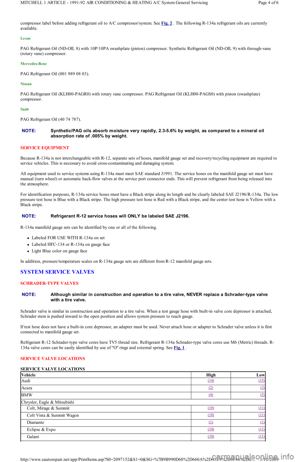
SERVICE VALVE LOCATIONS
SERVICE VALVE LOCATIONS NOTE:Synthetic/PAG oils absorb m oisture very rapidly, 2.3-5.6% by weight, as com pared to a m ineral oil
absorption rate of .005% by weight.
NOTE:Refrigerant R-12 service hoses will ONLY be labeled SAE J2196.
NOTE:Although sim ilar in construction and operation to a tire valve, NEVER replace a Schrader-type valve
with a tire valve.
VehicleHighLow
Audi(14) (15)
Acura(2) (3)
BMW(4) (5)
Chrysler, Eagle & Mitsubishi
Colt, Mirage & Summit(10) (11)
Colt Vista & Summit Wagon(10) (11)
Diamante(1) (1)
Eclipse & Expo(10) (11)
Galant(10) (11)
Page 4 of 6 MITCHELL 1 ARTICLE - 1991-92 AIR CONDITIONING & HEATING A/C System General Servicing
3/10/2009 http://www.eautorepair.net/app/PrintItems.asp?S0=2097152&S1=0&SG=%7B9B990D68%2D660A%2D45E9%2D8F46%2DE
...
Page 365 of 454
Back To Article
MAINTENANCE INFORMATION
1988-93 MAINT ENANCE Ford Motor Co. Maintenance Inform ation
MODEL IDENTIFICATION
VIN LOCATION
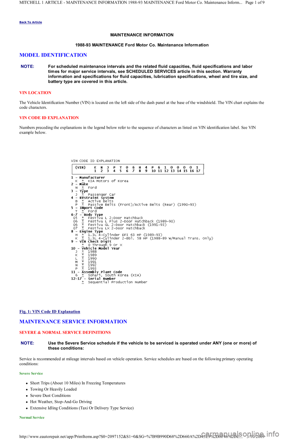
The Vehicle Identification Number (VIN) is located on the left side of the dash panel at the base of the windshield. The VIN chart explains the
code characters.
VIN CODE ID EXPLANATION
Numbers preceding the explanations in the legend below refer to the sequence of characters as listed on VIN identification label. See VIN
example below.
Fig. 1: VIN Code ID Explanation
MAINTENANCE SERVICE INFORMATION
SEVERE & NORMAL SERVICE DEFINITIONS
Service is recommended at mileage intervals based on vehicle operation. Service schedules are based on the following primary operating
conditions:
Severe Service
Short Trips (About 10 Miles) In Freezing Temperatures
Towing Or Heavily Loaded
Severe Dust Conditions
Hot Weather, Stop-And-Go Driving
Extensive Idling Conditions (Taxi Or Delivery Type Service)
Normal Service
NOTE:For scheduled m aintenance intervals and the related fluid capacities, fluid specifications and labor
tim es for m ajor service intervals, see SCHEDULED SERVICES article in this section. Warranty
inform ation and specifications for fluid capacities, lubrication specifications, wheel and tire size, and
battery type are covered in this article.
NOTE:Use the Severe Service schedule if the vehicle to be serviced is operated under ANY (one or m ore) of
these conditions:
Page 1 of 9 MITCHELL 1 ARTICLE - MAINTENANCE INFORMATION 1988-93 MAINTENANCE Ford Motor Co. Maintenance Inform...
3/10/2009 http://www.eautorepair.net/app/PrintItems.asp?S0=2097152&S1=0&SG=%7B9B990D68%2D660A%2D45E9%2D8F46%2DE
...
Page 397 of 454
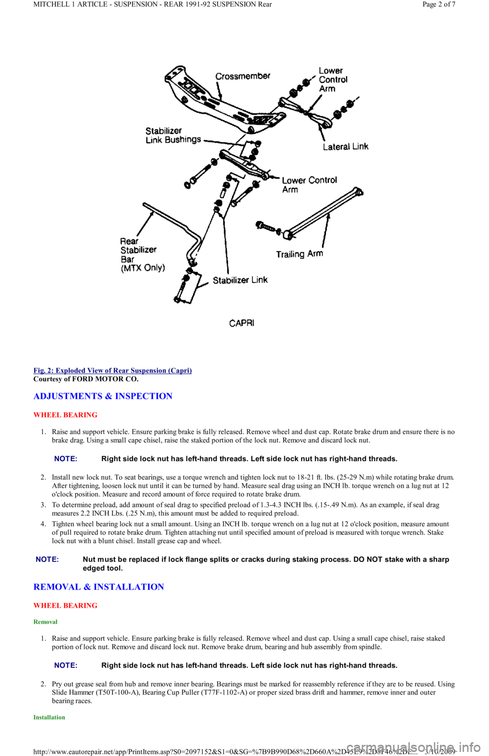
Fig. 2: Exploded View of Rear Suspension (Capri)
Courtesy of FORD MOTOR CO.
ADJUSTMENTS & INSPECTION
WHEEL BEARING
1. Raise and support vehicle. Ensure parking brake is fully released. Remove wheel and dust cap. Rotate brake drum and ensure there is no
brake drag. Using a small cape chisel, raise the staked portion of the lock nut. Remove and discard lock nut.
2. Install new lock nut. To seat bearings, use a torque wrench and tighten lock nut to 18-21 ft. lbs. (25-29 N.m) while rotating brake drum.
After tightening, loosen lock nut until it can be turned by hand. Measure seal drag using an INCH lb. torque wrench on a lug nut at 12
o'clock position. Measure and record amount of force required to rotate brake drum.
3. To determine preload, add amount of seal drag to specified preload of 1.3-4.3 INCH lbs. (.15-.49 N.m). As an example, if seal drag
measures 2.2 INCH Lbs. (.25 N.m), this amount must be added to required preload.
4. Tighten wheel bearing lock nut a small amount. Using an INCH lb. torque wrench on a lug nut at 12 o'clock position, measure amo u n t
of pull required to rotate brake drum. Tighten attaching nut until specified amount of preload is measured with torque wrench. Stake
lock nut with a blunt chisel. Install grease cap and wheel.
REMOVAL & INSTALLATION
WHEEL BEARING
Removal
1. Raise and support vehicle. Ensure parking brake is fully released. Remove wheel and dust cap. Using a small cape chisel, raise staked
portion of lock nut. Remove and discard lock nut. Remove brake drum, bearing and hub assembly from spindle.
2. Pry out grease seal from hub and remove inner bearing. Bearings must be marked for reassembly reference if they are to be reused. Using
Slide Hammer (T50T-100-A), Bearing Cup Puller (T77F-1102-A) or proper sized brass drift and hammer, remove inner and outer
bearing races.
Installation
NOTE:Right side lock nut has left-hand threads. Left side lock nut has right-hand threads.
NOTE:Nut m ust be replaced if lock flange splits or cracks during staking process. DO NOT stake with a sharp
edged tool.
NOTE:Right side lock nut has left-hand threads. Left side lock nut has right-hand threads.
Page 2 of 7 MITCHELL 1 ARTICLE - SUSPENSION - REAR 1991-92 SUSPENSION Rear
3/10/2009 http://www.eautorepair.net/app/PrintItems.asp?S0=2097152&S1=0&SG=%7B9B990D68%2D660A%2D45E9%2D8F46%2DE
...
Page 398 of 454
1. Using Installer (T77F-1217-A), Driver Handle (T80T-4000-W) or proper sized brass drift and hammer, install inner and outer bearing
races. Pack bearings and hub area with Lubricant (C1AZ-1959D-B, C, D or E).
2. Position inner bearing in bearing hub. Lubricate grease seal lips and install seal. Ensure bearings and hub have sufficient lubricant. Place
brake drum bearings and hub assembly on spindle. To prevent damage to grease seal and spindle threads, ensure hub is correctly
centered on spindle.
3. Install outer bearing, washer and new lock nut. Stake lock nut with a blunt chisel. Adjust bearing preload. See ADJUSTMENTS &
INSPECTION.
SPINDLE
Removal & Installation (Capri)
Remove wheel, caliper and brake rotor. Loosen spindle-to-strut attaching bolts. Loosen outer rear control arm common bolt and nut. Remove
spindle-to-strut mount bolts and common control arm bolt. Remove spindle from strut. To install, reverse removal procedure.
Removal & Installation (Festiva)
Remove brake drum assembly. Remove 4 spindle attaching nuts located on inboard side of torsion beam. Support backing plate with wire and
remove spindle. To install, reverse removal procedure. Tighten spindle attaching nuts to 32-45 ft. lbs. (43-61 N.m).
STRUTS
Removal & Installation (Capri)
1. Remove wheel, caliper and brake rotor. Remove trailing arm bolt and spindle-to-strut attaching bolts. Put index mark on strut rubber
mounting bracket. Remove upper strut attaching nuts from inside vehicle. Remove strut.
2. Compress strut coil spring with Spring Compressor (T18P-5310-A) or similar. Remove strut nut while spring is compressed. Remove
rubber mounting bracket, upper and lower spring seats. Slowly release coil spring and remove spring compressor. Remove coil spring,
dust boot and rebound bumpers. To install, reverse removal procedure.
Removal (Festiva)
1. Raise and support vehicle. Remove rear wheels. Using Spring Compressor (T81P-5310-A), compress spring to unload strut. Remove rear
quarter trim panel from cargo compartment.
2. Remove jam nut and flanged nut from strut rod. Remove bushing washer and upper bushing. Remove strut lower end mounting bolt
from wheel support arm. Remove strut and separate it from spring and seat insulator. Remove lower bushing and jounce bumper seat
from strut rod. Slide jounce bumper and shield off strut. See Fig. 3
. NOTE:Nut m ust be replaced if lock flange splits or cracks during staking process. DO NOT stake with a sharp-
edged tool.
Page 3 of 7 MITCHELL 1 ARTICLE - SUSPENSION - REAR 1991-92 SUSPENSION Rear
3/10/2009 http://www.eautorepair.net/app/PrintItems.asp?S0=2097152&S1=0&SG=%7B9B990D68%2D660A%2D45E9%2D8F46%2DE
...
Page 404 of 454
Back To Article
1983-95 WHEEL ALIGNMENT
Pre-Alignm ent Inspection Procedures
PRE-ALIGNMENT CHECKS
Before making wheel alignment adjustment, perform the following checks:
1. Tires should be equal in size and runout must not be excessive. Tires and wheels should be in balance, and inflated to manufacturer's
specifications.
2. Wheel bearings must be properly adjusted. Steering linkage and suspension must not have excessive looseness. Check for wear in tie rod
ends and ball joints.
3. Steering gear box must not have excessive play. Check and adjust to manufacturer's specifications.
4. Vehicle must be at curb height with full fuel load and spare tire in vehicle. No extra load should be on vehicle.
5. Vehicle must be level with floor and with suspension settled. Jounce front and rear of vehicle several times and allow it to settle to
normal curb height.
6. If steering wheel is not centered with front wheels in straight-ahead position, correct by shortening one tie rod adjusting sleeve and
lengthening opposite sleeve equal amounts.
7. Ensure wheel lug nuts are tightened to torque specifications.
Copyr ight 2009 Mitchell Repair Information Company, LLC. All Rights Reserved.
Article GUID: A00060347
Page 1 of 1 MITCHELL 1 ARTICLE - 1983-95 WHEEL ALIGNMENT Pre-Alignment Inspection Procedures
3/10/2009 http://www.eautorepair.net/app/PrintItems.asp?S0=2097152&S1=0&SG=%7B9B990D68%2D660A%2D45E9%2D8F46%2DE
...