1991 FORD FESTIVA air condition
[x] Cancel search: air conditionPage 32 of 454

lock nut. Discard axle lock nut. Separate tie rod end from knuckle.
2. Disconnect brake hose from strut (if necessary). Remove brake caliper assembly from knuckle and wire out of way. Remove nuts and
bolts holding ball joint and strut to knuckle assembly.
3. Remove knuckle assembly from ball joint and drive shaft. If binding occurs, use a dual-jawed puller to force knuckle/hub/rotor assembly
off drive axle shaft.
4. Using a puller, separate knuckle from wheel hub. Retain original outer bearing preload spacer to maintain bearing preload setting. If
replacing bearing, change spacer to maintain proper bearing preload (if necessary). See FRONT WHEEL BEARINGS under REMOVAL
& INSTALLATION. Scribe match marks between hub and rotor assembly. Remove rotor-to-hub bolts. Separate hub from rotor.
Installation
Align marks and install rotor on hub. Press knuckle and preload spacer into wheel hub assembly. To complete installation, reverse removal
procedure. Tighten axle shaft lock nut to 117-175 ft. lbs. (159-237 N.m).
REAR BRAKE CALIPER & PADS
Removal (Capri)
1. Raise and support vehicle. Remove tire and wheel assembly. Using needle-nose pliers, remove parking brake return spring. Loosen
parking brake cable housing adjusting nut. Remove cable housing from bracket on lower control arm. Loosen parking brake cable
bracket-to-caliper attaching bolt. Remove parking brake cable from caliper.
2. Remove lower caliper retaining bolt. Pivot caliper upward on upper caliper guide pin. Remove brake pad retaining spring, pads and
shims. If replacing rear brake pads only, reverse removal procedure to install. If removing caliper, proceed to next step.
3. Remove attaching clip from brake flex hose. Remove flex hose banjo bolt from caliper and discard copper washers. Remove lower
caliper retaining bolt. Using a cold chisel, remove upper caliper guide pin dust cap. Using an Allen wrench, remove upper caliper guide
pin. Lift caliper off rotor.
Installation
1. To install, fit brake pads and shims into caliper anchor plate. Remove upper guide pin and lower guide pin bushing from caliper.
Remove guide pin and guide pin bushing dust boots. Lubricate upper guide pin and lower guide pin bushing with Disc Brake Caliper
Slide Grease (D7AZ-19590-A).
2. To complete installation, reverse removal procedure. To fit caliper over new brake pads, it may be necessary to rotate caliper piston into
caliper bore. Use NEW copper washers on flex hose. Bleed brakes, and then pump brake pedal several times to seat pads.
REAR BRAKE ROTOR
Removal & Installation (Capri)
See REAR WHEEL BEARINGS under REMOVAL & INSTALLATION.
REAR BRAKE SHOES
Removal & Installation (Festiva)
Remove brake drum. Remove hold-down springs. Remove return springs. Remove self adjuster. See Fig. 8 . To install, reverse removal
procedure. Apply brake grease to all shoe contact points. See REAR BRAKE SHOES under ADJUSTMENTS.
REAR WHEEL CYLINDER
Removal & Installation (Festiva)
Remove rear brake shoes. Disconnect brake line from wheel cylinder. Remove wheel cylinder. To install, reverse removal procedure. Bleed
brake system.
MASTER BRAKE CYLINDER
Removal
Disconnect low fluid level sensor wiring (if equipped). Drain some brake fluid from reservoir. Disconnect brake lines from master cylinder.
Cap lines and master cylinder ports. Remove attaching nuts and master cylinder.
Installation
To install, reverse removal procedure. Fill master cylinder to proper level and bleed hydraulic system (if necessary).
POWER BRAKE UNIT
Removal & Installation
Remove master cylinder. Disconnect vacuum line. Remove clevis pin at brake pedal. Remove power brake unit. To install, reverse removal
procedure.
FRONT WHEEL BEARINGS NOTE:Hub and rotor are a m atched and balanced assem bly. Before rem oving rotor, locate paint or etch
m ark indicating proper hub-to-rotor alignm ent. If m arks are not present, m ark hub and rotor for
assem bly alignm ent. Failure to properly align hub and rotor can result in an im balance condition.
Page 5 of 12 MITCHELL 1 ARTICLE - BRAKE SYSTEM 1991-92 BRAKES Disc & Drum
3/10/2009 http://www.eautorepair.net/app/PrintItems.asp?S0=2097152&S1=0&SG=%7B7DD6473C%2DB5BB%2D4F20%2D9D70%2D
...
Page 49 of 454

Back To Article
FUSES & CIRCUIT BREAKERS
Fuses & Circuit Breakers 1988-93 Festiva
FUSES & FUSIBLE LINKS
FUSE PANEL & FUSIBLE LINK BLOCK LOCATIONS
The vehicle has a fuse block with fusible links and a fuse panel with circuit fuses. The fuse panel is located behind the instrument panel, left o
f
the steering column. The fuse block is located under the hood.
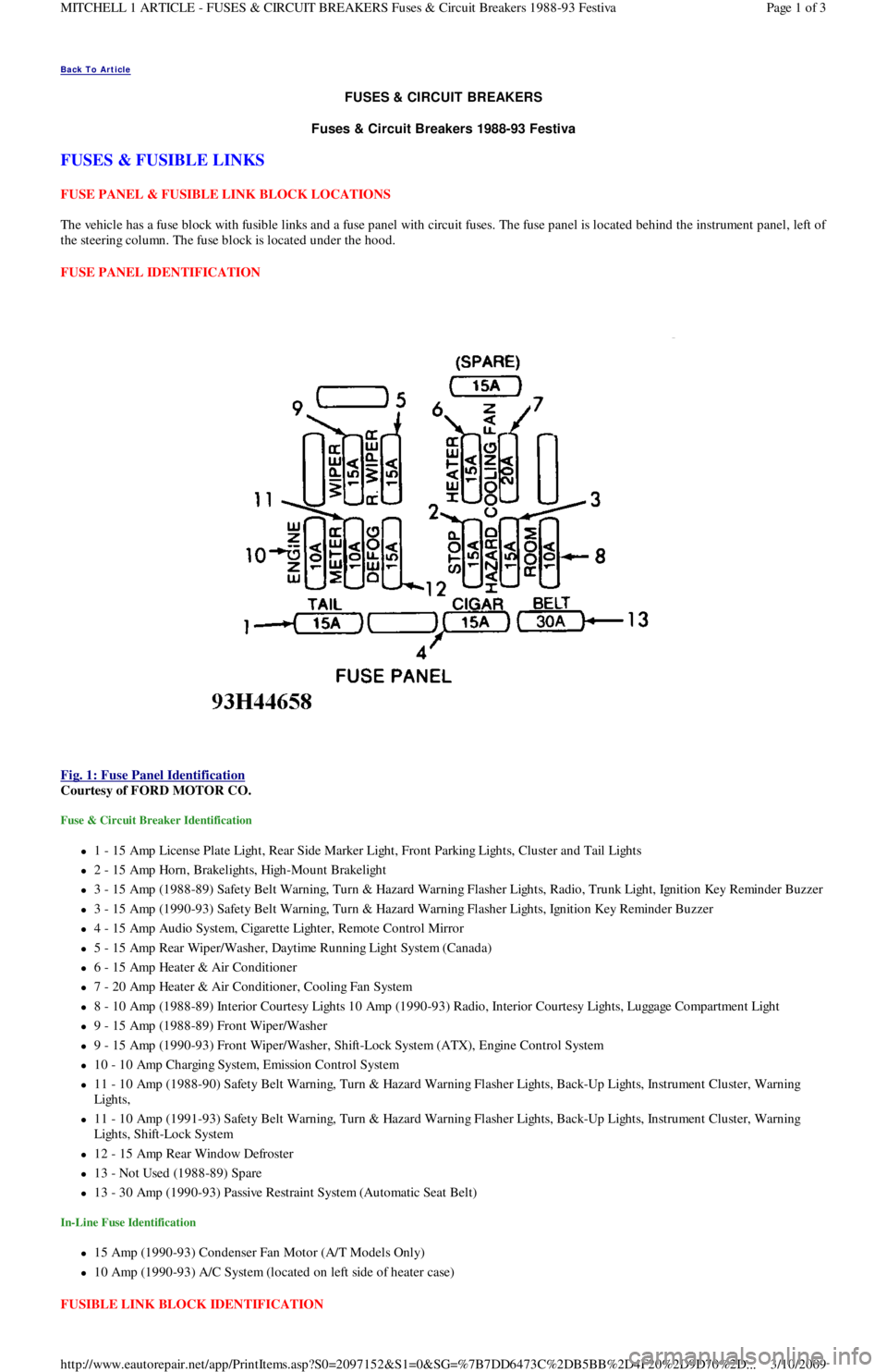
FUSE PANEL IDENTIFICATION
Fig. 1: Fuse Panel Identification
Courtesy of FORD MOTOR CO.
Fuse & Circuit Breaker Identification
1 - 15 Amp License Plate Light, Rear Side Marker Ligh t , Fr o n t P a r kin g Ligh t s, C l u st e r a n d Ta il Ligh t s
2 - 15 Amp Horn, Brakelights, High-Mount Brakelight
3 - 15 Amp (1988-89) Safety Belt Warning, Turn & Hazard Warning Flasher Lights, Radio, Trunk Light, Ignition Key Reminder Buzzer
3 - 15 Amp (1990-93) Safety Belt Warning, Turn & Hazard Warning Flasher Lights, Ignition Key Reminder Buzzer
4 - 15 Amp Audio System, Cigarette Lighter, Remote Control Mirror
5 - 15 Amp Rear Wiper/Washer, Daytime Running Light System (Canada)
6 - 15 Amp Heater & Air Conditioner
7 - 20 Amp Heater & Air Conditioner, Cooling Fan System
8 - 10 Amp (1988-89) Interior Courtesy Lights 10 Amp (1990-93) Radio, Interior Courtesy Lights, Luggage Compartment Light
9 - 15 Amp (1988-89) Front Wiper/Washer
9 - 15 Amp (1990-93) Front Wiper/Washer, Shift-Lock System (ATX), Engine Control System
10 - 10 Amp Charging System, Emission Control System
11 - 10 Amp (1988-90) Safety Belt Warning, Turn & Hazard Warning Flasher Lights, Back-Up Lights, Instrument Cluster, Warning
Lights,
11 - 10 Amp (1991-93) Safety Belt Warning, Turn & Hazard Warning Flasher Lights, Back-Up Lights, Instrument Cluster, Warning
Lights, Shift-Lock System
12 - 15 Amp Rear Window Defroster
13 - Not Used (1988-89) Spare
13 - 30 Amp (1990-93) Passive Restraint System (Automatic Seat Belt)
In-Line Fuse Identification
15 Amp (1990-93) Condenser Fan Motor (A/T Models Only)
10 Amp (1990-93) A/C System (located on left side of heater case)
FUSIBLE LINK BLOCK IDENTIFICATION
Page 1 of 3 MITCHELL 1 ARTICLE - FUSES & CIRCUIT BREAKERS Fuses & Circuit Breakers 1988-93 Festiva
3/10/2009 http://www.eautorepair.net/app/PrintItems.asp?S0=2097152&S1=0&SG=%7B7DD6473C%2DB5BB%2D4F20%2D9D70%2D
...
Page 102 of 454

levels to proper level.
Removal (1.6L & 1.6L Turbo)
1. Relieve fuel pressure and discharge air conditioning system (if equipped). See FUEL PRESSURE RELEASE under REMOVAL &
INSTALLATION. Disconnect and remove battery, battery tray and battery tray support bracket.
2. Release wiring harness retaining straps from battery support tray. Disconnect windshield washer supply hose between fluid reservoir and
hood. Mark hinge locations and remove hood.
3. Disconnect intake air tube and wiring to ignition coil and vane airflow meter. Remove air cleaner/vane airflow meter assembly. Remove
air cleaner assembly support brackets. Disconnect intercooler hoses from turbocharger (if equipped).
4. Drain engine coolant and remove radiator. Disconnect accelerator cable, and remove retaining bracket from cam cover. Position cable to
one side.
5. Disconnect and plug fuel lines at fuel filter and pressure regulator. Disconnect power brake booster manifold vacuum hose from
manifold. Disconnect heater hoses at heater core tubes. Label and remove vacuum hoses located at throttle body.
6. For manual transaxle turbocharged vehicles, disconnect clutch cable and remove support bracket and cable from transmission. On non-
turbo vehicles, disconnect clutch slave hydraulic line. For automatic transaxle, remove transaxle cooler lines.
7. Disconnect starter wiring at starter. Remove harness from locating strap on bracket. Disconnect alternator wiring. Disconnect wiring
from engine coolant sensors located on rear of engine block. Remove ground connection at bracket on thermostat cover. Disconnect O2
sensor wire, main wiring harness connector, TPS connector (turbocharged only), knock sensor connector, distributor wiring and
transaxle wiring. Disconnect ground wire and strap at front of engine, and reinstall lifting eye.
8. Remove engine oil dipstick and retaining clip. Remove power steering pump from mounting bracket. Remove power steering pump
mounting bracket. With hoses attached, position pump aside. Remove upper air conditioning compressor retaining bolts (if equipped).
9. Raise vehicle on hoist. Drain engine oil and cooling system. On vehicles with air conditioning, remove lower air conditioning
compressor mounting bolts, and position compressor out of way.
10. Remove front wheels and tires. Remove front ball joints-to-ste e r in g kn u c kl e s r e t a in in g b o l t s. R e mo ve sp l a sh gu a r d s. Dr a in t ransmission
oil and remove half shafts from differential. Remove front exhaust pipe bracket located on lower side of engine. Disconnect front
exhaust pipe from exhaust manifold, or turbocharger (if equipped).
11. Remove frame support bar-to-engine support bolt. Loosen right control arm bolt and, pivot support bar downward. Disengage rubber
exhaust hangers located directly behind catalytic converter. Allow exhaust system to hang down 6 inches, and support system with
mechanic's wire. Unbolt shift linkage and stabilizer bar at transaxle. Remove nuts from front and rear engine mounts, and lower vehicle.
12. Attach chains onto lift eyes at ends of cylinder head, and support engine with hoist. Remove RH engine mount through bolt. Raise
engine off mounts and slightly pivot engine/transaxle assembly. Disconnect oil pressure sensor and route starter/alternator wiring
harness from engine. Carefully lift engine/transaxle assembly, turn assembly while raising to clear brake master cylinder, shift linkage
universal joint, radiator support and air conditioning lines (if equipped).
13. Remove intake manifold support bracket. Remove gusset plate(s) (if equipped). Remove starter. Remove transaxle-to-engine retaining
bolts. Identify bolts to ensure correct installation. Separate transaxle from engine. On manual transaxle, remove pressure plate, clutch
disc and flywheel. On automatic transaxle, remove flexplate.
Installation (1.6L & 1.6L Turbo)
1. Install transaxle to engine in reverse order of removal. Attach hoist to engine/transaxle assembly and position assembly in vehicle.
Before engine contacts mounts, route starter, alternator and oil pressure sensor wiring, and connect oil pressure sensor. Lower engine
until front mount seats on crossmember. Install through bolt on RH engine mount. DO NOT tighten bolt.
2. Remove hoist. Raise vehicle and support with jackstands. Align rear engine mount to crossmember, and install retaining nuts to front
and rear engine mounts. Tighten nuts to specification. See TORQUE SPECIFICATIONS
table at end of article.
3. On manual transaxles, connect shift coupling and stabilizer. Tighten to specification. On automatic transaxles, connect shift linkage and
oil cooler lines. Tighten linkage retaining bolt, shift cable pivot and oil cooler hose clamps to specification. Connect front exhaust pipe
to manifold (or turbocharger). Install exhaust pipe to support bracket. Tighten bolts to specification. Tighten manifold (or turbocharger)
to specification. Attach rubber exhaust hangers. Position cross brace. Tighten retaining nut and bolt and right control arm front bolt.
4. Install drive axles. Install ball joint retaining bolts and tighten to specification. Mount A/C Compressor to engine (if equipped). Tighten
lower retaining bolts to specification. Install splash guards. Install tire and wheel assemblies. Tighten retaining nuts to specification.
5. Lower vehicle. Install upper A/C compressor retaining bolts (if equipped). Tighten bolts to specification. Tighten RH engine mo u n t
through bolt to specification. Connect alternator wiring.
6. Position power steering pump bracket on stud. Lower pump into engine compartment. Install power steering pump bracket retaining
bolts and nut. Tighten to specification. Install power steering pump and belt. Tighten adjustment nut and pivot bolt to specification.
7. Install engine oil dipstick and retaining clip. Install ground strap and ground wire to cylinder head. Install clutch cable (if equipped).
Connect clutch hydraulic line if equipped with manual transaxle or naturally aspirated. Connect transmission electrical connectors.
Connect fuel lines to fuel filter and pressure regulator. Install intake air tube to throttle body.
8. Install intercooler hoses on turbocharged models. Install air cleaner assembly brackets. Install air cleaner assembly with airflow meter
attached. Install intake air tube. Install coil and airflow meter connectors. Connect coolant crankcase and air bypass hoses. Install
vacuum hoses as noted in disassembly.
9. Connect accelerator cable. Install retaining bracket. Install power brake booster hose. Remove speedometer cable from transaxle. Fill
transaxle to specification. See CAPACITIES in SERVICE & ADJUSTMENT SPECIFICATIONS article. Install speedometer cable.
Connect speedometer cable connector. Fill engine oil to capacity.
10. Install radiator/fan assembly. Tighten bracket retaining bolts to specification. Connect coolant hoses and fan electrical connector. Fill
coolant to specification.
11. Install hood and connect washer hose. Install battery tray support, battery tray, battery and battery hold-down. Connect battery
terminal. Evacuate and charge air conditioning system (if equipped). Road test vehicle and inspect for leaks.
INTAKE MANIFOLD
Removal (1.3L)
CAUT ION: DO NOT allow com pressor to hang by hoses. T ie up com pressor with m echanic's wire.
Page 2 of 19 MITCHELL 1 ARTICLE - ENGINE OVERHAUL 1991-92 FORD MOTOR CO. ENGINES 1.3L & 1.6L 4-Cylinder
3/10/2009 http://www.eautorepair.net/app/PrintItems.asp?S0=2097152&S1=0&SG=%7B959286D2%2D3A85%2D4BFC%2D9C5C%2D
...
Page 129 of 454

Back To Article
D - ADJUSTMENTS
1991 ENGINE PERFORMANCE Ford/Mercury - On-Vehicle Adjustm ents
ADJUSTMENTS
ENGINE MECHANICAL
Before beginning any on-vehicle adjustments to fuel or ignition systems, ensure engine mechanical condition is okay.
VALVE CLEARANCE
IGNITION TIMING
CAPRI
1. Place automatic transmission in Park or manual transmission in Neutral. Disconnect and plug hoses attached to vacuum diaphragm
assembly on distributor. Connect tachometer and timing light. Turn off all electrical loads.
2. Start engine, and warm it to operating temperature. Ensure idle speed is set to specification, adjusting if necessary. See IDLE SPEED &
MIXTURE . Determine initial timing. See IGNITION TIMING table. If base timing is not correct, loosen distributor mounting bolts
and rotate distributor until marks align. Tighten bolts to 14-18 ft. lbs. (19-25 N.m).
3. Increase engine RPM while observing timing light. Verify ignition timing advances. For Turbo models, go to step 5). For non-Turbo
models, continue with step 4).
4. On non-Turbo models, apply 16 in. Hg vacuum to chamber "A". Verify timing advances by 26-30 degrees. Remove vacuum source from
chamber "A". Apply 8 in. Hg vacuum to chamber "B" while observing timing. Verify timing advances by 3-7 degrees. Stop engine, and
remove test equipment.
5. On Turbo models, apply 20 in. Hg vacuum to advance diaphragm. Verify timing advances by 13-17 degrees. Disconnect vacuum source.
Apply 8 psi (.6 kg/cm
2 ) pressure to advance diaphragm. Verify timing retards by 3-7 degrees. Stop engine, and remove test equipment.
FESTIVA
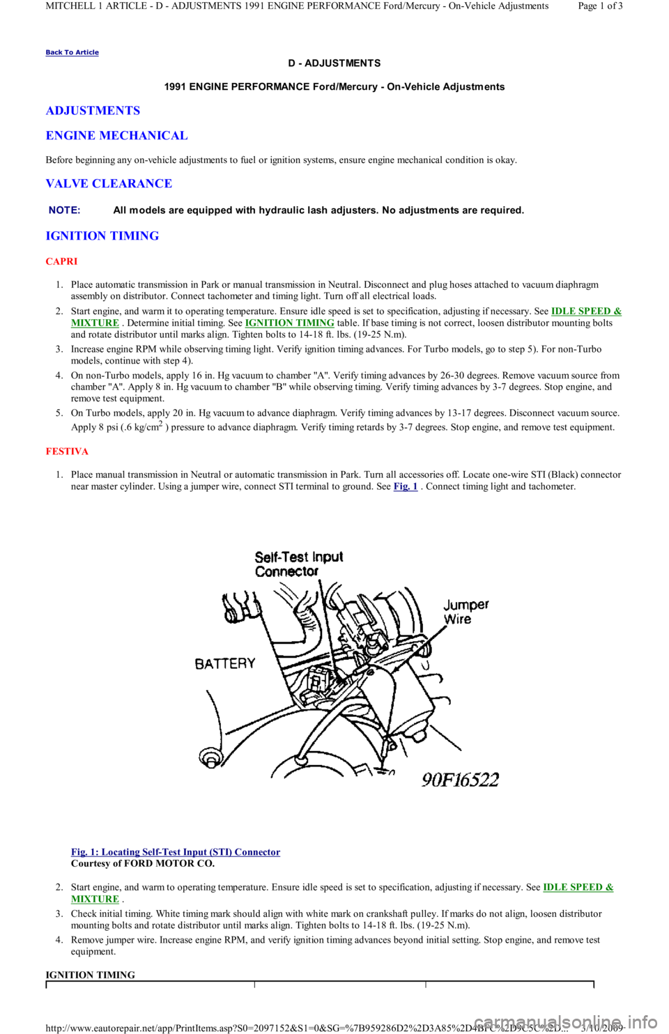
1. Place manual transmission in Neutral or automatic transmission in Park. Turn all accessories off. Locate one-wire STI (Black) connector
near master cylinder. Using a jumper wire, connect STI terminal to ground. See Fig. 1
. Connect timing light and tachometer.
Fig. 1: Locating Self
-Test Input (STI) Connector
Courtesy of FORD MOTOR CO.
2. Start engine, and warm to operating temperature. Ensure idle speed is set to specification, adjusting if necessary. See IDLE SPEED &
MIXTURE .
3. Check initial timing. White timing mark should align with white mark on crankshaft pulley. If marks do not align, loosen distributor
mounting bolts and rotate distributor until marks align. Tighten bolts to 14-18 ft. lbs. (19-25 N.m).
4. Remove jumper wire. Increase engine RPM, and verify ignition timing advances beyond initial setting. Stop engine, and remove test
equipment.
IGNITION TIMING NOTE:All m odels are equipped with hydraulic lash adjusters. No adjustm ents are required.
Page 1 of 3 MITCHELL 1 ARTICLE - D - ADJUSTMENTS 1991 ENGINE PERFORMANCE Ford/Mercury - On-Vehicle Adjustments
3/10/2009 http://www.eautorepair.net/app/PrintItems.asp?S0=2097152&S1=0&SG=%7B959286D2%2D3A85%2D4BFC%2D9C5C%2D
...
Page 131 of 454

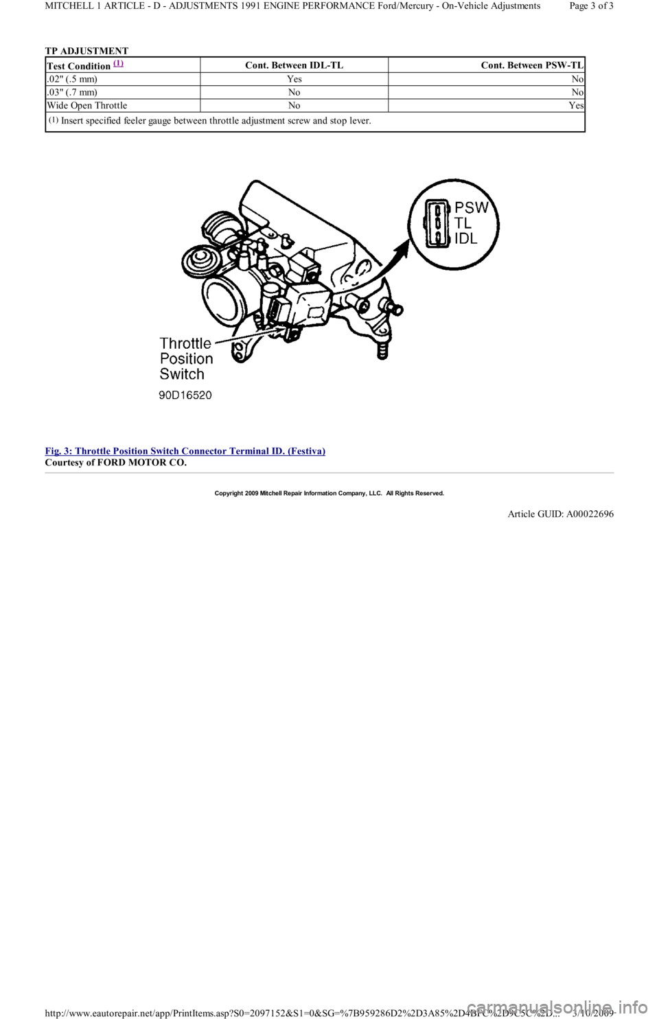
TP ADJUSTMENT
Fig. 3: Throttle Position Switch Connector Terminal ID. (Festiva)
Courtesy of FORD MOTOR CO.
Test Condition (1) Cont. Between IDL-TLCont. Between PSW-TL
.02" (.5 mm)YesNo
.03" (.7 mm)NoNo
Wide Open ThrottleNoYes
(1)Insert specified feeler gauge between throttle adjustment screw and stop lever.
Copyr ight 2009 Mitchell Repair Information Company, LLC. All Rights Reserved.
Article GUID: A00022696
Page 3 of 3 MITCHELL 1 ARTICLE - D - ADJUSTMENTS 1991 ENGINE PERFORMANCE Ford/Mercury - On-Vehicle Adjustments
3/10/2009 http://www.eautorepair.net/app/PrintItems.asp?S0=2097152&S1=0&SG=%7B959286D2%2D3A85%2D4BFC%2D9C5C%2D
...
Page 142 of 454

Back To Article
J - PIN VOLT AGE CHART S
1991 ENGINE PERFORMANCE Ford/Mercury Pin Voltage Charts
INTRODUCTION
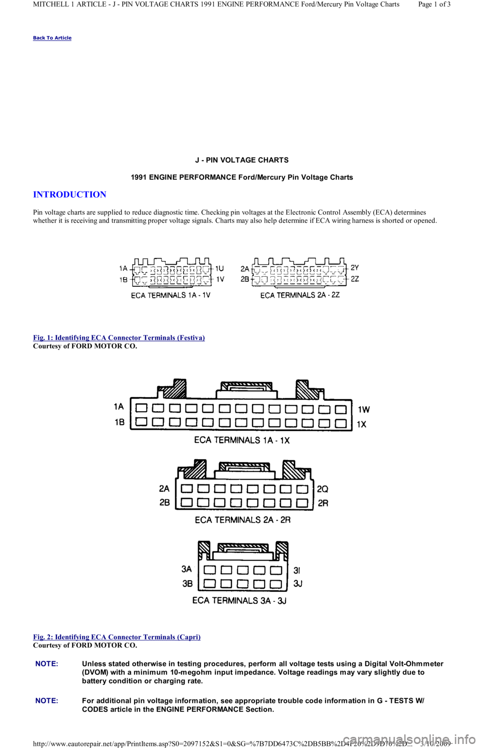
Pin voltage charts are supplied to reduce diagnostic time. Checking pin voltages at the Electronic Control Assembly (ECA) determin es
whether it is receiving and transmitting proper voltage signals. Charts may also help determine if ECA wiring harness is shorted or opened.
Fig. 1: Identifying ECA Connector Terminals (Festiva)
Courtesy of FORD MOTOR CO.
Fig. 2: Identifying ECA Connector Terminals (Capri)
Courtesy of FORD MOTOR CO.
NOTE:Unless stated otherwise in testing procedures, perform all voltage tests using a Digital Volt-Ohm m eter
(DVOM) with a m inim um 10-m egohm input im pedance. Voltage readings m ay vary slightly due to
battery condition or charging rate.
NOTE:For additional pin voltage inform ation, see appropriate trouble code inform ation in G - T EST S W/
CODES article in the ENGINE PERFORMANCE Section.
Page 1 of 3 MITCHELL 1 ARTICLE - J - PIN VOLTAGE CHARTS 1991 ENGINE PERFORMANCE Ford/Mercury Pin Voltage Charts
3/10/2009 http://www.eautorepair.net/app/PrintItems.asp?S0=2097152&S1=0&SG=%7B7DD6473C%2DB5BB%2D4F20%2D9D70%2D
...
Page 155 of 454

FUEL SYSTEM
FUEL PUMP
FUEL PUMP PERFORMANCE
INJECTOR RESISTANCE
FUEL INJECTOR RESISTANCE
IDLE SPEED
IDLE SPEED
(1)
THROTTLE POSITION SWITCH (TPS)
TPS ADJUSTMENT NOTE:For fuel pressure specifications, see FUEL PRESSURE SPECIFICAT IONS
article.
NOTE:Fuel pum p perform ance is a m easurem ent of fuel pressure and volum e availability, not regulated fuel
pressure.
ApplicationPressure -psi kg/cm2 )Min. Vol. in 10 sec. oz. (CC)
1.3L(1) 7.4 (220)
1.6L(1) 5.5 (167)
(1)For fuel pressure specifications, see FUEL PRESSURE SPECIFICATIONS article.
ApplicationOhms
1.3L & 1.6L12-16
ApplicationAuto. Trans.Man. Trans.
1.3L830-870680-720
1.6L800-900800-900
(1)With jumper wire connected between single-wire STI terminal and ground.
NOTE:Capri is equipped with throttle position sensor. No adjustm ent is required.
Test Condition (1) Cont. Between IDL-TLCont. Between PSW-TL
.02" (.5 mm)YesNo
.03" (.7 mm)NoNo
Wide Open ThrottleNoYes
(1)Insert specified feeler gauge between throttle adjustment screw and stop lever.
Copyr ight 2009 Mitchell Repair Information Company, LLC. All Rights Reserved.
Article GUID: A00022695
Page 3 of 3 MITCHELL 1 ARTICLE - C - SPECIFICATIONS 1991 ENGINE PERFORMANCE Ford/Mercury - Service & Adjustment Spe
...
3/10/2009 http://www.eautorepair.net/app/PrintItems.asp?S0=2097152&S1=0&SG=%7B7DD6473C%2DB5BB%2D4F20%2D9D70%2D
...
Page 156 of 454

Back To Article
F - BASIC TESTING
1991-92 ENGINE PERFORMANCE Ford Motor Co. Basic Diagnostic Procedures
INTRODUCTION
The following diagnostic steps help prevent overlooking simple problems and begin diagnosis for a no-start condition.
The first step in diagnosing any driveability problem is to verify the complaint. Test drive the vehicle under the conditions in which the
problem reportedly occurred.
Before entering self-diagnostics, perform a careful and complete visual inspection. Most engine control problems result from mechanical
breakdowns, poor electrical connections or damaged/misrouted vacuum hoses. Before condemning the computerized system, perform each test
listed in this article.
PRELIMINARY INSPECTION & ADJUSTMENTS
VISUAL INSPECTION
Perform a visual inspection of all electrical wiring. Look for chafed, stretched, cut or pinched wiring. Ensure electrical connections fit tightly
and are not corroded. Ensure vacuum hoses are properly routed and are not cut or pinched. If necessary, see VACUUM DIAGRAMS article in
the ENGINE PERFORMANCE Section to verify routing and connections. Inspect air induction system for possible vacuum leaks.
MECHANICAL INSPECTION
Compression
Engine mechanical condition can be checked using a compression gauge, vacuum gauge or engine analyzer. See engine analyzer instruction
manual for specific instructions. Lowest compression reading must be not less than 75 percent of highest reading.
Exhaust System Backpressure
Exhaust system can be checked with a vacuum gauge or a 0-5 psi pressure gauge. If a pressure gauge is used, remove O2 sensor. Connect gauge
to O2 sensor port. Start engine, and run at 2500 RPM. If exhaust system backpressure is more than 2 psi, exhaust system or catalytic converter
is plugged.
If a vacuum gauge is used, connect it to intake manifold vacuum. Start engine. Observe vacuum gauge. Open throttle part way and hold steady.
If vacuum gauge drops slowly after stabilizing, check exhaust system for a restriction.
FUEL PRESSURE
Fuel Pressure Release
Start engine (if possible), and unplug VAF meter connector. When engine stalls, turn ignition off and reconnect VAF meter wiring. Usin g sh o p
towel, cover fitting to absorb leakage when opening fuel system.
Fuel Pressure Check
1. Connect fuel pressure gauge between fuel filter and fuel rail. Open main valve, and close drain valve. Locate fuel pump check connector
in engine compartment, near left strut. Connect jumper wire between fuel pump test terminals (Black and Green/White wires on Capri
or Black and Green/Red wires on Festiva).
2. Turn ignition on to activate fuel pump. If pump does not run, check fuel pump circuit. If possible, start engine. Measure and record fuel
pressure. For fuel pressure specifications, see FUEL PRESSURE SPECIFICATIONS
article. Disconnect vacuum from pressure
regulator. Turn engine off. Wait 5 minutes and ensure residual pressure is at least 21 psi (1.5 kg/cm
2 ).
3. Operate fuel pump by reconnecting jumper wire at fuel pump check connector. Check fuel pump performance. Pinch hose between
pressure gauge and fuel filter. Do not hold longer than necessary to check pressure.For fuel pressure specifications, see FUEL
PRESSURE SPECIFICATIONS article. If pump does not meet specifications, check fuel pump circuit, fuel pump, fuel tank and fuel
filter or replace fuel pump.
FUEL PUMP PERFORMANCE NOTE:Unless stated otherwise in test procedure, perform all voltage tests with a Digital Volt-Ohm m eter
(DVOM) with a m inim um 10-m egohm input im pedance.
CAUT ION: DO NOT use ignition switch during com pression tests on fuel injected vehicles. Fuel injectors are
triggered by ignition switch during cranking m ode. Use a rem ote starter to crank engine to prevent fire
hazard and catalytic converter and engine oiling system contam ination.
WARNING:ALWAYS relieve fuel pressure before disconnecting any fuel injection system com ponent. DO NOT
allow fuel to contact engine or electrical com ponents.
NOTE:For 1991 fuel pressure specifications, see FUEL PRESSURE SPECIFICAT IONS
article. For 1992 fuel
pressure specifications, see FUEL PRESSURE SPECIFICAT IONS
article.
ApplicationPressure psi (kg/cm2 )Min. Vol. in 10 sec. Ozs. (cc)
Capri(1) 5.5 (167)
Festiva(1) 7.4 (220)
Page 1 of 4 MITCHELL 1 ARTICLE - F - BASIC TESTING 1991-92 ENGINE PERFORMANCE Ford Motor Co. Basic Diagnostic Proced
...
3/10/2009 http://www.eautorepair.net/app/PrintItems.asp?S0=2097152&S1=0&SG=%7B959286D2%2D3A85%2D4BFC%2D9C5C%2D
...