1991 FORD FESTIVA air bleeding
[x] Cancel search: air bleedingPage 28 of 454
Back To Article
BRAKE SYST EM
1991-92 BRAKES Disc & Drum
DESCRIPTION & OPERATION
On Capri, vehicle braking is provided by front and rear disc brakes. Front and rear brakes are a full-floating, single piston design. The rear
caliper houses a self-adjusting parking brake.
On Festiva, vehicle braking is provided by front disc brakes and rear drum brakes. Rear brakes are a standard non-servo, self-en e r giz in g d e sign .
Front brakes are a full-floating, single piston design with caliper attached to steering knuckle.
BLEEDING BRAKE SYSTEM
BLEEDING PROCEDURES
Manual Bleeding
1. Exhaust vacuum from power brake unit by depressing brake pedal several times. Fill master cylinder with clean brake fluid. Install clear
vinyl bleeder hose onto first bleeder valve to be serviced. See BRAKE LINE BLEEDING SEQUENCE table. Place other end of hose in
clean transparent container.
2. Partially fill container with clean brake fluid. Open the bleeder valve 3/4 turn. Slowly depress brake pedal through its full travel. Close
bleeder valve and release pedal. Pump pedal several times to push air toward wheel cylinders. Repeat procedure until flow of brake
fluid is clear and shows no signs of air bubbles. Proceed to next bleeder valve in sequence and repeat procedure.
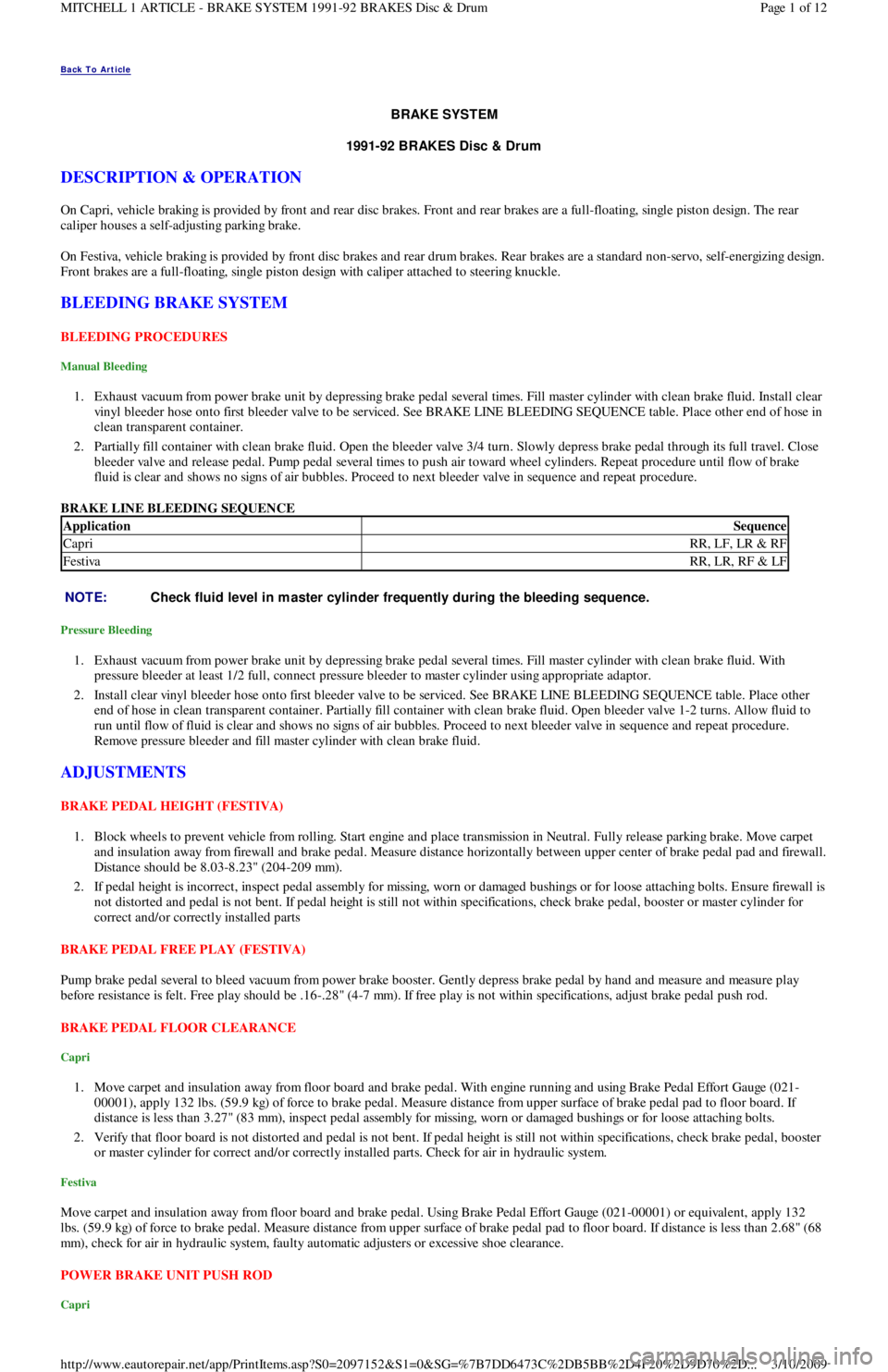
BRAKE LINE BLEEDING SEQUENCE
Pressure Bleeding
1. Exhaust vacuum from power brake unit by depressing brake pedal several times. Fill master cylinder with clean brake fluid. With
pressure bleeder at least 1/2 full, connect pressure bleeder to master cylinder using appropriate adaptor.
2. Install clear vinyl bleeder hose onto first bleeder valve to be serviced. See BRAKE LINE BLEEDING SEQUENCE table. Place other
end of hose in clean transparent container. Partially fill container with clean brake fluid. Open bleeder valve 1-2 turns. Allow fluid to
run until flow of fluid is clear and shows no signs of air bubbles. Proceed to next bleeder valve in sequence and repeat procedure.
Remove pressure bleeder and fill master cylinder with clean brake fluid.
ADJUSTMENTS
BRAKE PEDAL HEIGHT (FESTIVA)
1. Block wheels to prevent vehicle from rolling. Start engine and place transmission in Neutral. Fully release parking brake. Move carpet
and insulation away from firewall and brake pedal. Measure distance horizontally between upper center of brake pedal pad and firewall.
Distance should be 8.03-8.23" (204-209 mm).
2. If pedal height is incorrect, inspect pedal assembly for missing, worn or damaged bushings or for loose attaching bolts. Ensure firewall is
not distorted and pedal is not bent. If pedal height is still not within specifications, check brake pedal, booster or master cylinder for
correct and/or correctly installed parts
BRAKE PEDAL FREE PLAY (FESTIVA)
Pump brake pedal several to bleed vacuum from power brake booster. Gently depress brake pedal by hand and measure and measure play
before resistance is felt. Free play should be .16-.28" (4-7 mm). If free play is not within specifications, adjust brake pedal push rod.
BRAKE PEDAL FLOOR CLEARANCE
Capri
1. Move carpet and insulation away from floor board and brake pedal. With engine running and using Brake Pedal Effort Gauge (021-
00001), apply 132 lbs. (59.9 kg) of force to brake pedal. Measure distance from upper surface of brake pedal pad to floor board. If
distance is less than 3.27" (83 mm), inspect pedal assembly for missing, worn or damaged bushings or for loose attaching bolts.
2. Verify that floor board is not distorted and pedal is not bent. If pedal height is still not within specifications, check brake pedal, booster
or master cylinder for correct and/or correctly installed parts. Check for air in hydraulic system.
Festiva
Move carpet and insulation away from floor board and brake pedal. Using Brake Pedal Effort Gauge (021-00001) or equivalent, apply 132
lbs. (59.9 kg) of force to brake pedal. Measure distance from upper surface of brake pedal pad to floor board. If distance is less than 2.68" (68
mm), check for air in hydraulic system, faulty automatic adjusters or excessive shoe clearance.
POWER BRAKE UNIT PUSH ROD
Capri
ApplicationSequence
CapriRR, LF, LR & RF
FestivaRR, LR, RF & LF
NOTE:Check fluid level in m aster cylinder frequently during the bleeding sequence.
Page 1 of 12 MITCHELL 1 ARTICLE - BRAKE SYSTEM 1991-92 BRAKES Disc & Drum
3/10/2009 http://www.eautorepair.net/app/PrintItems.asp?S0=2097152&S1=0&SG=%7B7DD6473C%2DB5BB%2D4F20%2D9D70%2D
...
Page 221 of 454
ENGINE MECHANICAL
COOLING SYSTEM TROUBLE SHOOTING
COOLING SYSTEM TROUBLE SHOOTING
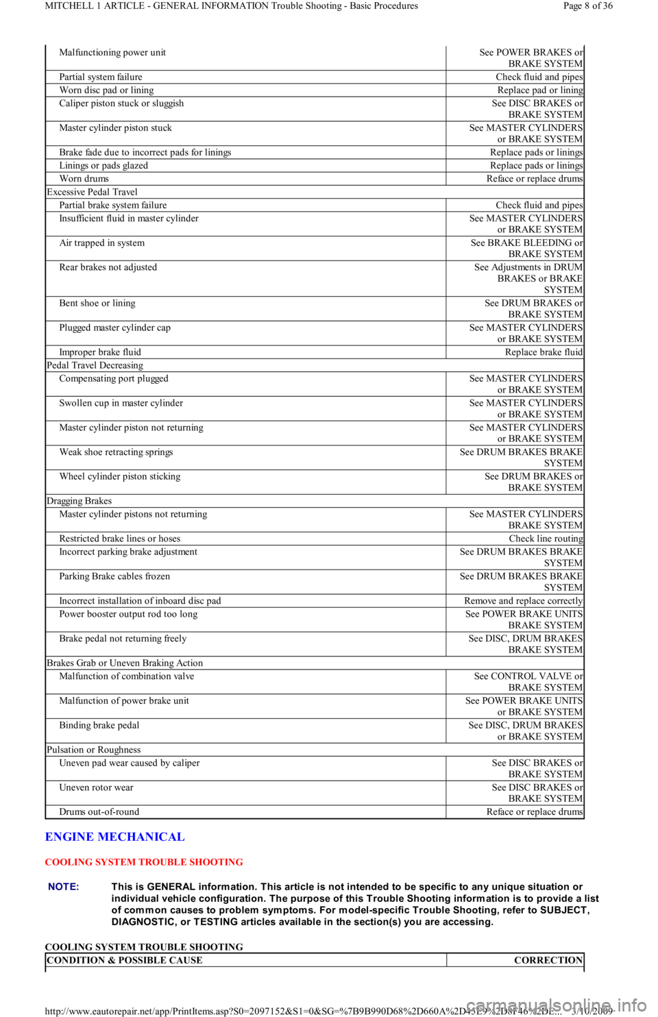
Malfunctioning power unitSee POWER BRAKES or
BRAKE SYSTEM
Partial system failureCheck fluid and pipes
Worn disc pad or liningReplace pad or lining
Caliper piston stuck or sluggishSee DISC BRAKES or
BRAKE SYSTEM
Master cylinder piston stuckSee MASTER CYLINDERS
or BRAKE SYSTEM
Brake fade due to incorrect pads for liningsReplace pads or linings
Linings or pads glazedReplace pads or linings
Worn drumsReface or replace drums
Excessive Pedal Travel
Partial brake system failureCheck fluid and pipes
Insufficient fluid in master cylinderSee MASTER CYLINDERS
or BRAKE SYSTEM
Air trapped in systemSee BRAKE BLEEDING or
BRAKE SYSTEM
Rear brakes not adjustedSee Adjustments in DRUM
BRAKES or BRAKE
SYSTEM
Bent shoe or liningSee DRUM BRAKES or
BRAKE SYSTEM
Plugged master cylinder capSee MASTER CYLINDERS
or BRAKE SYSTEM
Improper brake fluidReplace brake fluid
Pedal Travel Decreasing
Compensating port pluggedSee MASTER CYLINDERS
or BRAKE SYSTEM
Swollen cup in master cylinderSee MASTER CYLINDERS
or BRAKE SYSTEM
Master cylinder piston not returningSee MASTER CYLINDERS
or BRAKE SYSTEM
Weak shoe retracting springsSee DRUM BRAKES BRAKE
SYSTEM
Wheel cylinder piston stickingSee DRUM BRAKES or
BRAKE SYSTEM
Dragging Brakes
Master cylinder pistons not returningSee MASTER CYLINDERS
BRAKE SYSTEM
Restricted brake lines or hosesCheck line routing
Incorrect parking brake adjustmentSee DRUM BRAKES BRAKE
SYSTEM
Parking Brake cables frozenSee DRUM BRAKES BRAKE
SYSTEM
Incorrect installation of inboard disc padRemove and replace correctly
Power booster output rod too longSee POWER BRAKE UNITS
BRAKE SYSTEM
Brake pedal not returning freelySee DISC, DRUM BRAKES
BRAKE SYSTEM
Brakes Grab or Uneven Braking Action
Malfunction of combination valveSee CONTROL VALVE or
BRAKE SYSTEM
Malfunction of power brake unitSee POWER BRAKE UNITS
or BRAKE SYSTEM
Binding brake pedalSee DISC, DRUM BRAKES
or BRAKE SYSTEM
Pulsation or Roughness
Uneven pad wear caused by caliperSee DISC BRAKES or
BRAKE SYSTEM
Uneven rotor wearSee DISC BRAKES or
BRAKE SYSTEM
Drums out-of-roundReface or replace drums
NOTE:This is GENERAL inform ation. This article is not intended to be specific to any unique situation or
individual vehicle configuration. T he purpose of this T rouble Shooting inform ation is to provide a list
of com m on causes to problem sym ptom s. For m odel-specific T rouble Shooting, refer to SUBJECT ,
DIAGNOST IC, or T EST ING articles available in the section(s) you are accessing.
CONDITION & POSSIBLE CAUSECORRECTION
Page 8 of 36 MITCHELL 1 ARTICLE - GENERAL INFORMATION Trouble Shooting - Basic Procedures
3/10/2009 http://www.eautorepair.net/app/PrintItems.asp?S0=2097152&S1=0&SG=%7B9B990D68%2D660A%2D45E9%2D8F46%2DE
...
Page 378 of 454
Back To Article
ST EERING SYST EM - POWER
1991-92 ST EERING Ford Motor Co. - Steering - Power Rack & Pinion
DESCRIPTION & OPERATION
Power steering system consists of a rack and pinion steering gear, valve body, power steering pump, fluid reservoir and interconnecting
hydraulic lines. Pressure and return lines from pump are connected to valve body. A vane-type power steering pump draws fluid from the
steering reservoir. Fluid is compressed by rotor and vanes inside steering pump and sent to steering gear. Pressure is monitored and controlled
by a pressure switch and a control valve located inside of steering pump.
TROUBLE SHOOTING
Refer to TROUBLE SHOOTING - BASIC PROCEDURES article in the GENERAL TROUBLE SHOOTING section.
LUBRICATION
CAPACITY
Information is not available.
FLUID TYPE
Use Dexron-II ATF type fluid.
FLUID LEVEL CHECK
Check fluid level before engine is started, while fluid is still cool. Remove reservoir cap fluid indicator on steering pump. Check fluid level.
Fluid should be between the "L" and "H" marks on the level gauge dipstick. If fluid is needed, fill to the "L" mark on dipstick. Run engine until
warm and turn steering wheel fully in both directions about 10 times. Return steering to straight-ahead position and shut engine off. Ensure
fluid level is between "L" and "H" marks. Add fluid if necessary.
HYDRAULIC FLUID BLEEDING
1. Raise and support front of vehicle. Ensure pump reservoir is filled to specified level. With ignition coil wire disconnected, crank engine
and add fluid to steering pump until fluid level remains constant. While cranking engine, rotate steering from stop to stop. Recheck and
add fluid as necessary.
2. Start engine and allow to idle for several minutes. Turn steering wheel completely lock-to-lock several times. Check fluid level. Add
fluid as necessary. Continue this procedure until there is no bubbling or decrease in fluid level.
ADJUSTMENTS
BELT TENSION
On Festiva, remove air duct and air cleaner. On all models, loosen steering pump mounting pivot bolt and the adjusting bolt lock nut. Using
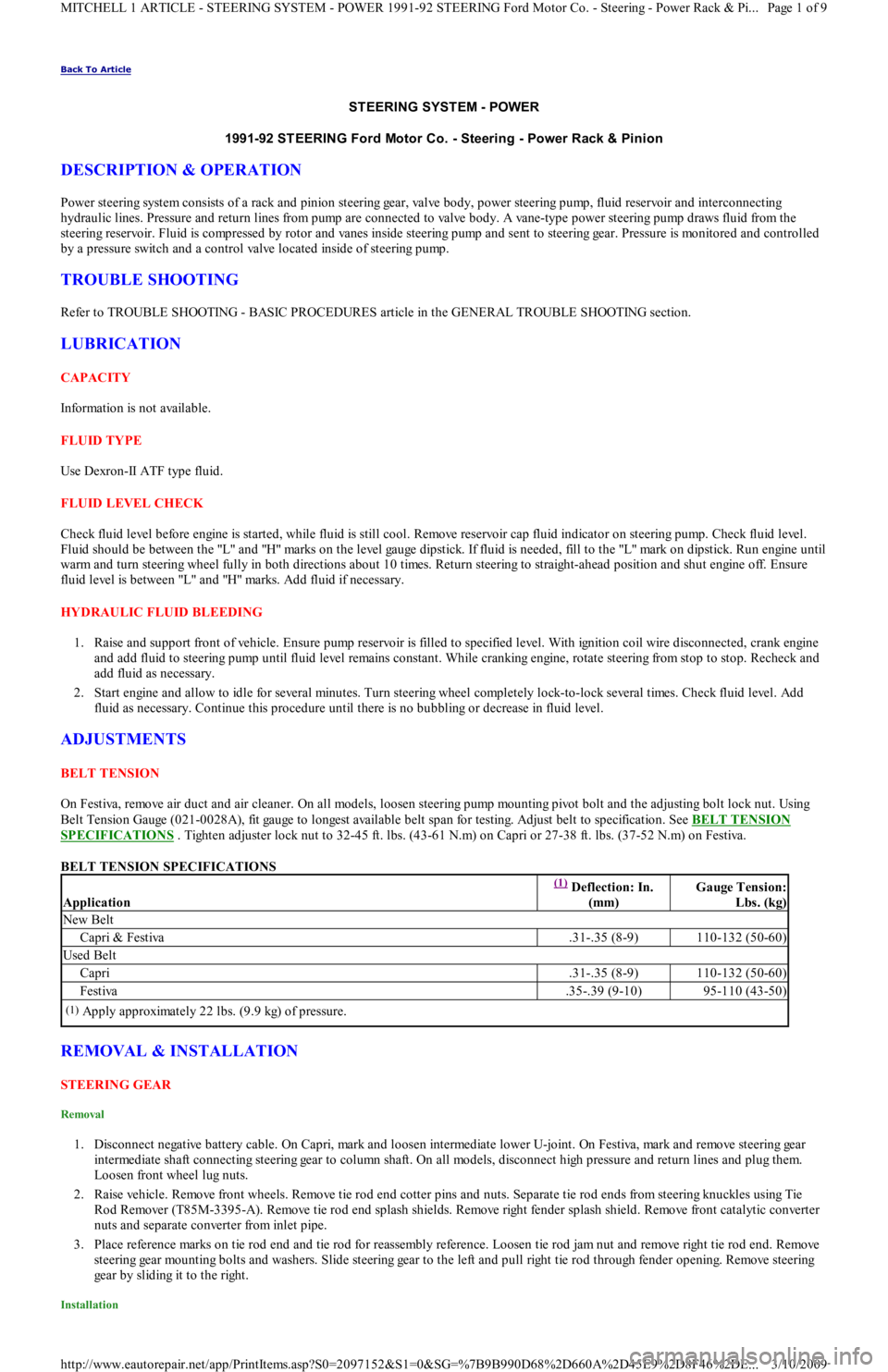
Belt Tension Gauge (021-0028A), fit gauge to longest available belt span for testing. Adjust belt to specification. See BELT TENSION
SPECIFICATIONS . Tighten adjuster lock nut to 32-45 ft. lbs. (43-61 N.m) on Capri or 27-38 ft. lbs. (37-52 N.m) on Festiva.
BELT TENSION SPECIFICATIONS
REMOVAL & INSTALLATION
STEERING GEAR
Removal
1. Disconnect negative battery cable. On Capri, mark and loosen intermediate lower U-joint. On Festiva, mark and remove steering gear
intermediate shaft connecting steering gear to column shaft. On all models, disconnect high pressure and return lines and plug them.
Loosen front wheel lug nuts.
2. Raise vehicle. Remove front wheels. Remove tie rod end cotter pins and nuts. Separate tie rod ends from steering knuckles using Tie
Rod Remover (T85M-3395-A). Remove tie rod end splash shields. Remove right fender splash shield. Remove front catalytic converter
nuts and separate converter from inlet pipe.
3. Place reference marks on tie rod end and tie rod for reassembly reference. Loosen tie rod jam nut and remove right tie rod end. Remove
steering gear mounting bolts and washers. Slide steering gear to the left and pull right tie rod through fender opening. Remove steering
gear by sliding it to the right.
Installation
Application
(1) Deflection: In.
(mm)Gauge Tension:
Lbs. (kg)
New Belt
Capri & Festiva.31-.35 (8-9)110-132 (50-60)
Used Belt
Capri.31-.35 (8-9)110-132 (50-60)
Festiva.35-.39 (9-10)95-110 (43-50)
(1)Apply approximately 22 lbs. (9.9 kg) of pressure.
Page 1 of 9 MITCHELL 1 ARTICLE - STEERING SYSTEM - POWER 1991-92 STEERING Ford Motor Co. - Steering - Power Rack & Pi
...
3/10/2009 http://www.eautorepair.net/app/PrintItems.asp?S0=2097152&S1=0&SG=%7B9B990D68%2D660A%2D45E9%2D8F46%2DE
...
Page 379 of 454
1. Position steering gear in its mounting position. Attach intermediate shaft to steering gear pinion and tighten clamp bolt to 13-20 ft. lbs.
(18-26 N.m). Guide intermediate shaft into steering column hole. Lower vehicle.
2. Lift steering gear and align intermediate shaft with universal joint and install clamp bolt. Raise vehicle. Install steering gear mounting
bolts and tighten to 23-34 ft. lbs. (31-46 N.m). Install right tie rod end, using marks made during removal for installation reference.
Attach tie rod ends to steering knuckles. Install tie rod end nuts and tighten to 22-33 ft. lbs. (29-44 N.m).
3. Install tie rod end cotter pins. Attach catalytic converter to inlet pipe and install attaching nuts. Tighten nuts to 23-34 ft. lbs. (31-46
N.m). Install tie rod end splash shields. Install right fender splash shield. install front wheels. Lower vehicle.
4. Connect high pressure and return lines. Connect negative battery cable. Add power steering fluid and bleed air from system and check
for leaks. See HYDRAULIC FLUID BLEEDING
under LUBRICATION.
POWER STEERING PUMP
Removal (Capri)
1. Remove right radiator support and brace. Remove pump drive belt. Disconnect intercooler outlet hose at throttle intake (if equipped).
R e mo ve gr o u n d wir e fr o m e n gin e l ift in g e ye .
2. Remove pressure and return hoses and plug. Remove wire from pressure switch. Remove adjusting screw, nut and block from pump
bracket. Remove pivot bolt. Remove bracket retaining bolts then remove pump.
Removal (Festiva)
Remove air duct and air cleaner. Disconnect electrical connector from fluid pressure switch on power steering pump. Disconnect and plug
return and pressure lines. Remove adjustment bolt. Remove lock nut, washer and bracket bolt. Loosen mounting bolt and disconnect drive
belt. Remove mounting bolt. Remove power steering pump.
Installation (Capri & Festiva)
To install pump, reverse removal procedure. Adjust steering belt tension. Tighten all nuts and bolts to specification. See TORQUE
SPECIFICATIONS . Add power steering fluid and bleed air from system and check for leaks. See HYDRAULIC FLUID BLEEDING
under LUBRICATION.
OVERHAUL
STEERING GEAR
Disassembly (Capri)
1. Remove steering gear and place in soft-jawed vise. Remove external hydraulic lines. See Fig. 1 . Remove mount brackets and rubber
mount bushings. Remove brass tubing seats using a self-tapping screw and 2 screwdrivers.
Page 2 of 9 MITCHELL 1 ARTICLE - STEERING SYSTEM - POWER 1991-92 STEERING Ford Motor Co. - Steering - Power Rack & Pi
...
3/10/2009 http://www.eautorepair.net/app/PrintItems.asp?S0=2097152&S1=0&SG=%7B9B990D68%2D660A%2D45E9%2D8F46%2DE
...
Page 385 of 454
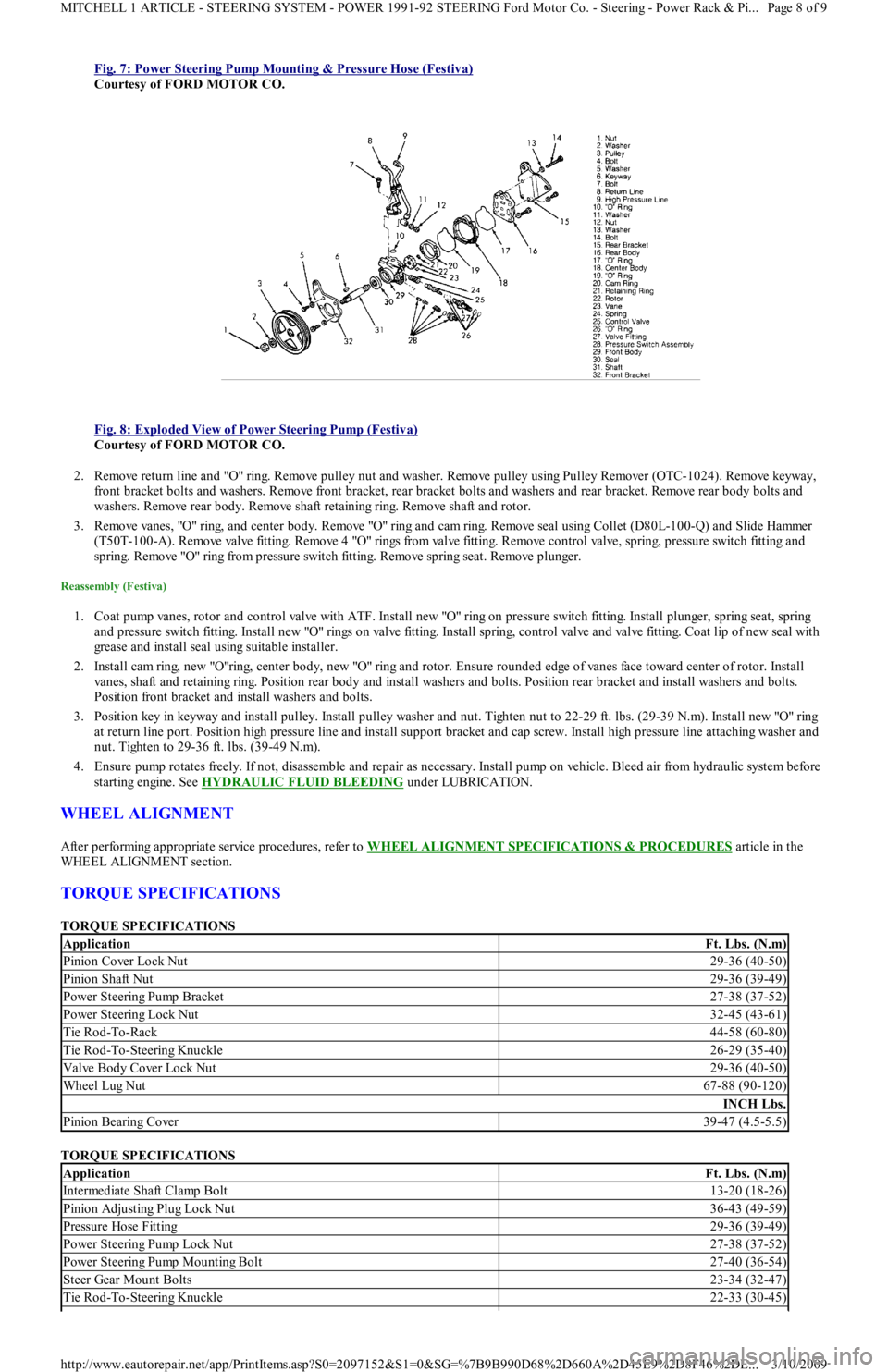
Fig. 7: Power Steering Pump Mounting & Pressure Hose (Festiva)
Courtesy of FORD MOTOR CO.
Fig. 8: Exploded View of Power Steering Pump (Festiva)
Courtesy of FORD MOTOR CO.
2. Remove return line and "O" ring. Remove pulley nut and washer. Remove pulley using Pulley Remover (OTC-1024). Remove keyway,
front bracket bolts and washers. Remove front bracket, rear bracket bolts and washers and rear bracket. Remove rear body bolts and
washers. Remove rear body. Remove shaft retaining ring. Remove shaft and rotor.
3. Remove vanes, "O" ring, and center body. Remove "O" ring and cam ring. Remove seal using Collet (D80L-100-Q) and Slide Hammer
( T5 0 T- 1 0 0 - A) . R e mo ve va l ve fit t in g. R e mo ve 4 "O" r in gs fr o m va l ve fit t in g. R e mo ve c o n t r o l va l ve , sp r in g, p r e ssu r e swit c h fit t ing a n d
spring. Remove "O" ring from pressure switch fitting. Remove spring seat. Remove plunger.
Reassembly (Festiva)
1. Coat pump vanes, rotor and control valve with ATF. Install new "O" ring on pressure switch fitting. Install plunger, spring seat, spring
and pressure switch fitting. Install new "O" rings on valve fitting. Install spring, control valve and valve fitting. Coat lip of new seal with
grease and install seal using suitable installer.
2. Install cam ring, new "O"ring, center body, new "O" ring and rotor. Ensure rounded edge of vanes face toward center of rotor. In st al l
vanes, shaft and retaining ring. Position rear body and install washers and bolts. Position rear bracket and install washers and bolts.
Position front bracket and install washers and bolts.
3. Position key in keyway and install pulley. Install pulley washer and nut. Tighten nut to 22-29 ft. lbs. (29-39 N.m). Install new "O" ring
at return line port. Position high pressure line and install support bracket and cap screw. Install high pressure line attaching washer and
nut. Tighten to 29-36 ft. lbs. (39-49 N.m).
4. Ensure pump rotates freely. If not, disassemble and repair as necessary. Install pump on vehicle. Bleed air from hydraulic system before
starting engine. See HYDRAULIC FLUID BLEEDING
under LUBRICATION.
WHEEL ALIGNMENT
After performing appropriate service procedures, refer to WHEEL ALIGNMENT SPECIFICATIONS & PROCEDURES article in the
WHEEL ALIGNMENT section.
TORQUE SPECIFICATIONS
TORQUE SPECIFICATIONS
TORQUE SPECIFICATIONS
ApplicationFt. Lbs. (N.m)
Pinion Cover Lock Nut29-36 (40-50)
Pinion Shaft Nut29-36 (39-49)
Power Steering Pump Bracket27-38 (37-52)
Power Steering Lock Nut32-45 (43-61)
Tie Rod-To-Rack44-58 (60-80)
Tie Rod-To-Steering Knuckle26-29 (35-40)
Valve Body Cover Lock Nut29-36 (40-50)
Wheel Lug Nut67-88 (90-120)
INCH Lbs.
Pinion Bearing Cover39-47 (4.5-5.5)
ApplicationFt. Lbs. (N.m)
Intermediate Shaft Clamp Bolt13-20 (18-26)
Pinion Adjusting Plug Lock Nut36-43 (49-59)
Pressure Hose Fitting29-36 (39-49)
Power Steering Pump Lock Nut27-38 (37-52)
Power Steering Pump Mounting Bolt27-40 (36-54)
Steer Gear Mount Bolts23-34 (32-47)
Tie Rod-To-Steering Knuckle22-33 (30-45)
Page 8 of 9 MITCHELL 1 ARTICLE - STEERING SYSTEM - POWER 1991-92 STEERING Ford Motor Co. - Steering - Power Rack & Pi
...
3/10/2009 http://www.eautorepair.net/app/PrintItems.asp?S0=2097152&S1=0&SG=%7B9B990D68%2D660A%2D45E9%2D8F46%2DE
...