1991 FORD FESTIVA change wheel
[x] Cancel search: change wheelPage 30 of 454
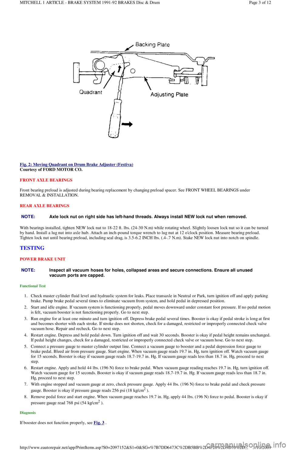
Fig. 2: Moving Quadrant on Drum Brake Adjuster (Festiva)
Courtesy of FORD MOTOR CO.
FRONT AXLE BEARINGS
Front bearing preload is adjusted during bearing replacement by changing preload spacer. See FRONT WHEEL BEARINGS under
REMOVAL & INSTALLATION.
REAR AXLE BEARINGS
With bearings installed, tighten NEW lock nut to 18-22 ft. lbs. (24-30 N.m) while rotating wheel. Slightly loosen lock nut so it can be turned
by hand. Install a lug nut into axle hub. Attach an inch-pound torque wrench to lug nut at 12 o'clock position. Measure bearing preload.
Tighten lock nut until bearing preload, including seal drag, is 3.5-6.2 INCH lbs. (.4-.7 N.m). Stake NEW lock nut into notch on spindle.
TESTING
POWER BRAKE UNIT
Functional Test
1. Check master cylinder fluid level and hydraulic system for leaks. Place transaxle in Neutral or Park, turn ignition off and apply parking
brake. Pump brake pedal several times to eliminate vacuum from system, and hold pedal in depressed position.
2. Start and idle engine. If vacuum system is functioning properly, pedal moves downward under constant foot pressure. If no pedal motion
is felt, vacuum booster is not functioning properly. Go to next step.
3. Run engine for at least one minute and turn ignition off. Depress brake pedal several times. Booster is okay if pedal stroke is long at first
and becomes shorter with each stroke. If stroke does not shorten, check for a damaged, restricted or improperly connected check va l ve
vacuum hose. Repair and recheck. Go to next step.
4. Restart engine. Depress and hold pedal down. Turn ignition off and wait 30 seconds. Booster is okay if pedal height remains unchanged.
If pedal height changes, check for a damaged, restricted or improperly connected check valve or vacuum hose. Go to next step.
5. Connect a pressure gauge to master cylinder output line. Connect a vacuum gauge to booster and a pedal depression force gauge to
brake pedal. Bleed air from pressure gauge. Start engine. When vacuum gauge reads 19.7 in. Hg, turn ignition off. Watch vacuum ga u ge
for 15 seconds. Booster is okay if vacuum gauge reads 18.7-19.7 in. Hg. If vacuum gauge reads less than 18.7 in. Hg, proceed to next
step.
6. Restart engine. Apply and hold 44 lbs. (196 N) force to brake pedal. When vacuum gauge reading reaches 19.7 in. Hg, turn ignition off.
Watch vacuum gauge for 15 seconds. Booster is okay if vacuum gauge reads 18.7-19.7 in. Hg. If vacuum gauge reads less than 18.7 in.
Hg, proceed to next step.
7. With engine stopped and vacuum gauge at zero, check pressure gauge. Apply 44 lbs. (196 N) force to brake pedal and check pressure
gauge. Booster is okay if pressure gauge reads 256 psi (18 kg/cm
2 ).
8. Remove pedal force and start engine. When vacuum gauge reaches 19.7 in. Hg, apply 44 lbs. (196 N) force to pedal. Booster is okay if
pressure gauge read 768 psi (54 kg/cm
2 ).
Diagnosis
If booster does not function properly, see Fig. 3 .
NOTE:Axle lock nut on right side has left-hand threads. Always install NEW lock nut when rem oved.
NOTE:Inspect all vacuum hoses for holes, collapsed areas and secure connections. Ensure all unused
vacuum ports are capped.
Page 3 of 12 MITCHELL 1 ARTICLE - BRAKE SYSTEM 1991-92 BRAKES Disc & Drum
3/10/2009 http://www.eautorepair.net/app/PrintItems.asp?S0=2097152&S1=0&SG=%7B7DD6473C%2DB5BB%2D4F20%2D9D70%2D
...
Page 32 of 454

lock nut. Discard axle lock nut. Separate tie rod end from knuckle.
2. Disconnect brake hose from strut (if necessary). Remove brake caliper assembly from knuckle and wire out of way. Remove nuts and
bolts holding ball joint and strut to knuckle assembly.
3. Remove knuckle assembly from ball joint and drive shaft. If binding occurs, use a dual-jawed puller to force knuckle/hub/rotor assembly
off drive axle shaft.
4. Using a puller, separate knuckle from wheel hub. Retain original outer bearing preload spacer to maintain bearing preload setting. If
replacing bearing, change spacer to maintain proper bearing preload (if necessary). See FRONT WHEEL BEARINGS under REMOVAL
& INSTALLATION. Scribe match marks between hub and rotor assembly. Remove rotor-to-hub bolts. Separate hub from rotor.
Installation
Align marks and install rotor on hub. Press knuckle and preload spacer into wheel hub assembly. To complete installation, reverse removal
procedure. Tighten axle shaft lock nut to 117-175 ft. lbs. (159-237 N.m).
REAR BRAKE CALIPER & PADS
Removal (Capri)
1. Raise and support vehicle. Remove tire and wheel assembly. Using needle-nose pliers, remove parking brake return spring. Loosen
parking brake cable housing adjusting nut. Remove cable housing from bracket on lower control arm. Loosen parking brake cable
bracket-to-caliper attaching bolt. Remove parking brake cable from caliper.
2. Remove lower caliper retaining bolt. Pivot caliper upward on upper caliper guide pin. Remove brake pad retaining spring, pads and
shims. If replacing rear brake pads only, reverse removal procedure to install. If removing caliper, proceed to next step.
3. Remove attaching clip from brake flex hose. Remove flex hose banjo bolt from caliper and discard copper washers. Remove lower
caliper retaining bolt. Using a cold chisel, remove upper caliper guide pin dust cap. Using an Allen wrench, remove upper caliper guide
pin. Lift caliper off rotor.
Installation
1. To install, fit brake pads and shims into caliper anchor plate. Remove upper guide pin and lower guide pin bushing from caliper.
Remove guide pin and guide pin bushing dust boots. Lubricate upper guide pin and lower guide pin bushing with Disc Brake Caliper
Slide Grease (D7AZ-19590-A).
2. To complete installation, reverse removal procedure. To fit caliper over new brake pads, it may be necessary to rotate caliper piston into
caliper bore. Use NEW copper washers on flex hose. Bleed brakes, and then pump brake pedal several times to seat pads.
REAR BRAKE ROTOR
Removal & Installation (Capri)
See REAR WHEEL BEARINGS under REMOVAL & INSTALLATION.
REAR BRAKE SHOES
Removal & Installation (Festiva)
Remove brake drum. Remove hold-down springs. Remove return springs. Remove self adjuster. See Fig. 8 . To install, reverse removal
procedure. Apply brake grease to all shoe contact points. See REAR BRAKE SHOES under ADJUSTMENTS.
REAR WHEEL CYLINDER
Removal & Installation (Festiva)
Remove rear brake shoes. Disconnect brake line from wheel cylinder. Remove wheel cylinder. To install, reverse removal procedure. Bleed
brake system.
MASTER BRAKE CYLINDER
Removal
Disconnect low fluid level sensor wiring (if equipped). Drain some brake fluid from reservoir. Disconnect brake lines from master cylinder.
Cap lines and master cylinder ports. Remove attaching nuts and master cylinder.
Installation
To install, reverse removal procedure. Fill master cylinder to proper level and bleed hydraulic system (if necessary).
POWER BRAKE UNIT
Removal & Installation
Remove master cylinder. Disconnect vacuum line. Remove clevis pin at brake pedal. Remove power brake unit. To install, reverse removal
procedure.
FRONT WHEEL BEARINGS NOTE:Hub and rotor are a m atched and balanced assem bly. Before rem oving rotor, locate paint or etch
m ark indicating proper hub-to-rotor alignm ent. If m arks are not present, m ark hub and rotor for
assem bly alignm ent. Failure to properly align hub and rotor can result in an im balance condition.
Page 5 of 12 MITCHELL 1 ARTICLE - BRAKE SYSTEM 1991-92 BRAKES Disc & Drum
3/10/2009 http://www.eautorepair.net/app/PrintItems.asp?S0=2097152&S1=0&SG=%7B7DD6473C%2DB5BB%2D4F20%2D9D70%2D
...
Page 33 of 454
Removal
Remove rotor and hub assembly from steering knuckle. Separate rotor, knuckle and hub. See FRONT BRAKE ROTOR & HUB under
REMOVAL & INSTALLATION. Press outer bearing from hub using Bearing Splitter (D84L-1123-A) and Shaft Protector (D80L-625-2).
Remove and discard outer grease seal. Pry inner wheel bearing grease seal from steering knuckle using a large screwdriver. Discard seal.
R e mo ve in n e r b e a r in g.
Bearing Preload
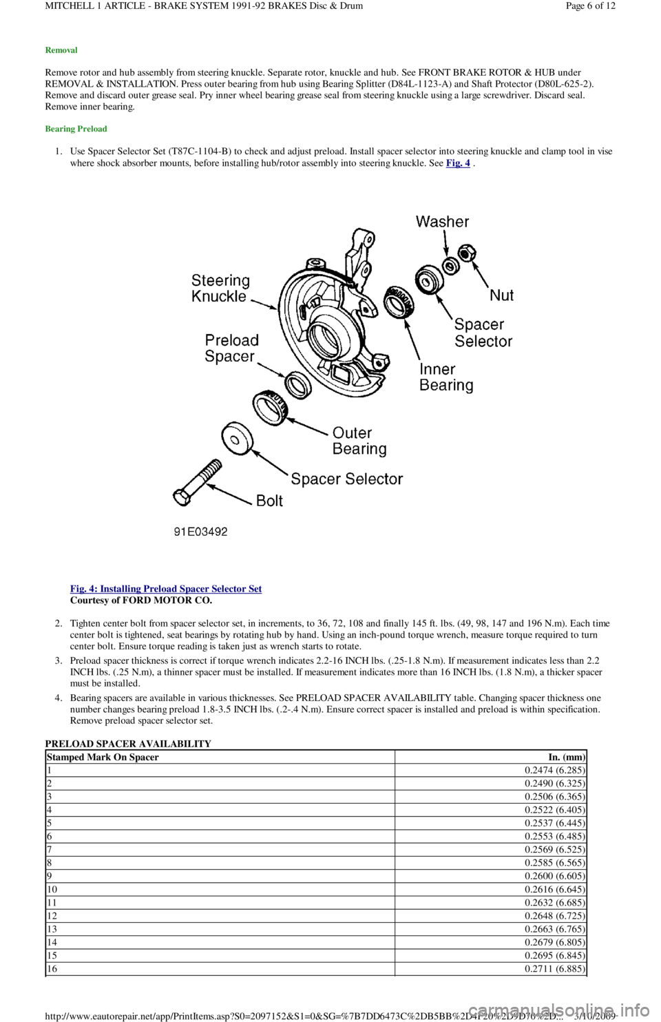
1. Use Spacer Selector Set (T87C-1104-B) to check and adjust preload. Install spacer selector into steering knuckle and clamp tool in vise
where shock absorber mounts, before installing hub/rotor assembly into steering knuckle. See Fig. 4
.
Fig. 4: Installing Preload Spacer Selector Set
Courtesy of FORD MOTOR CO.
2. Tighten center bolt from spacer selector set, in increments, to 36, 72, 108 and finally 145 ft. lbs. (49, 98, 147 and 196 N.m). Each time
center bolt is tightened, seat bearings by rotating hub by hand. Using an inch-pound torque wrench, measure torque required to turn
center bolt. Ensure torque reading is taken just as wrench starts to rotate.
3. Preload spacer thickness is correct if torque wrench indicates 2.2-16 INCH lbs. (.25-1.8 N.m). If measurement indicates less than 2.2
INCH lbs. (.25 N.m), a thinner spacer must be installed. If measurement indicates more than 16 INCH lbs. (1.8 N.m), a thicker spacer
must be installed.
4. Bearing spacers are available in various thicknesses. See PRELOAD SPACER AVAILABILITY table. Changing spacer thickness one
number changes bearing preload 1.8-3.5 INCH lbs. (.2-.4 N.m). Ensure correct spacer is installed and preload is within specification.
Remove preload spacer selector set.
PRELOAD SPACER AVAILABILITY
Stamped Mark On SpacerIn. (mm)
10.2474 (6.285)
20.2490 (6.325)
30.2506 (6.365)
40.2522 (6.405)
50.2537 (6.445)
60.2553 (6.485)
70.2569 (6.525)
80.2585 (6.565)
90.2600 (6.605)
100.2616 (6.645)
110.2632 (6.685)
120.2648 (6.725)
130.2663 (6.765)
140.2679 (6.805)
150.2695 (6.845)
160.2711 (6.885)
Page 6 of 12 MITCHELL 1 ARTICLE - BRAKE SYSTEM 1991-92 BRAKES Disc & Drum
3/10/2009 http://www.eautorepair.net/app/PrintItems.asp?S0=2097152&S1=0&SG=%7B7DD6473C%2DB5BB%2D4F20%2D9D70%2D
...
Page 220 of 454
BRAKES
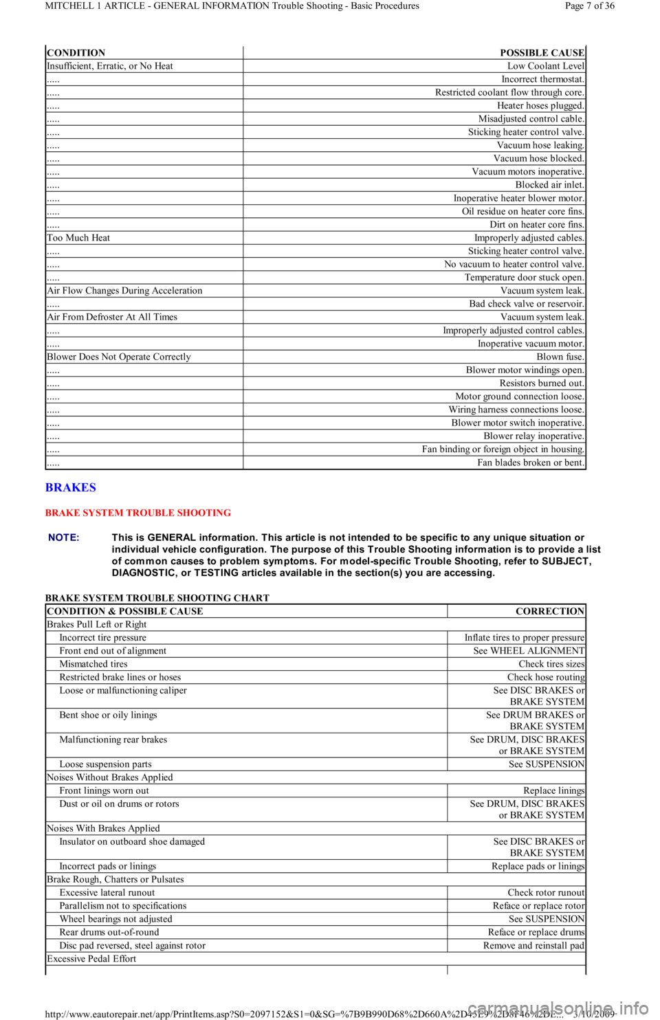
BRAKE SYSTEM TROUBLE SHOOTING
BRAKE SYSTEM TROUBLE SHOOTING CHART
CONDITIONPOSSIBLE CAUSE
Insufficient, Erratic, or No HeatLow Coolant Level
.....Incorrect thermostat.
.....Restricted coolant flow through core.
.....Heater hoses plugged.
.....Misadjusted control cable.
.....Sticking heater control valve.
.....Vacuum hose leaking.
.....Vacuum hose blocked.
.....Vacuum motors inoperative.
.....Blocked air inlet.
.....Inoperative heater blower motor.
.....Oil residue on heater core fins.
.....Dirt on heater core fins.
Too Much HeatImproperly adjusted cables.
.....Sticking heater control valve.
.....No vacuum to heater control valve.
.....Temperature door stuck open.
Air Flow Changes During AccelerationVacuum system leak.
.....Bad check valve or reservoir.
Air From Defroster At All TimesVacuum system leak.
.....Improperly adjusted control cables.
.....Inoperative vacuum motor.
Blower Does Not Operate CorrectlyBlown fuse.
.....Blower motor windings open.
.....Resistors burned out.
.....Motor ground connection loose.
.....Wiring harness connections loose.
.....Blower motor switch inoperative.
.....Blower relay inoperative.
.....Fan binding or foreign object in housing.
.....Fan blades broken or bent.
NOTE:This is GENERAL inform ation. This article is not intended to be specific to any unique situation or
individual vehicle configuration. T he purpose of this T rouble Shooting inform ation is to provide a list
of com m on causes to problem sym ptom s. For m odel-specific T rouble Shooting, refer to SUBJECT ,
DIAGNOST IC, or T EST ING articles available in the section(s) you are accessing.
CONDITION & POSSIBLE CAUSECORRECTION
Brakes Pull Left or Right
Incorrect tire pressureInflate tires to proper pressure
Front end out of alignmentSee WHEEL ALIGNMENT
Mismatched tiresCheck tires sizes
Restricted brake lines or hosesCheck hose routing
Loose or malfunctioning caliperSee DISC BRAKES or
BRAKE SYSTEM
Bent shoe or oily liningsSee DRUM BRAKES or
BRAKE SYSTEM
Malfunctioning rear brakesSee DRUM, DISC BRAKES
or BRAKE SYSTEM
Loose suspension partsSee SUSPENSION
Noises Without Brakes Applied
Front linings worn outReplace linings
Dust or oil on drums or rotorsSee DRUM, DISC BRAKES
or BRAKE SYSTEM
Noises With Brakes Applied
Insulator on outboard shoe damagedSee DISC BRAKES or
BRAKE SYSTEM
Incorrect pads or liningsReplace pads or linings
Brake Rough, Chatters or Pulsates
Excessive lateral runoutCheck rotor runout
Parallelism not to specificationsReface or replace rotor
Wheel bearings not adjustedSee SUSPENSION
Rear drums out-of-roundReface or replace drums
Disc pad reversed, steel against rotorRemove and reinstall pad
Excessive Pedal Effort
Page 7 of 36 MITCHELL 1 ARTICLE - GENERAL INFORMATION Trouble Shooting - Basic Procedures
3/10/2009 http://www.eautorepair.net/app/PrintItems.asp?S0=2097152&S1=0&SG=%7B9B990D68%2D660A%2D45E9%2D8F46%2DE
...
Page 234 of 454
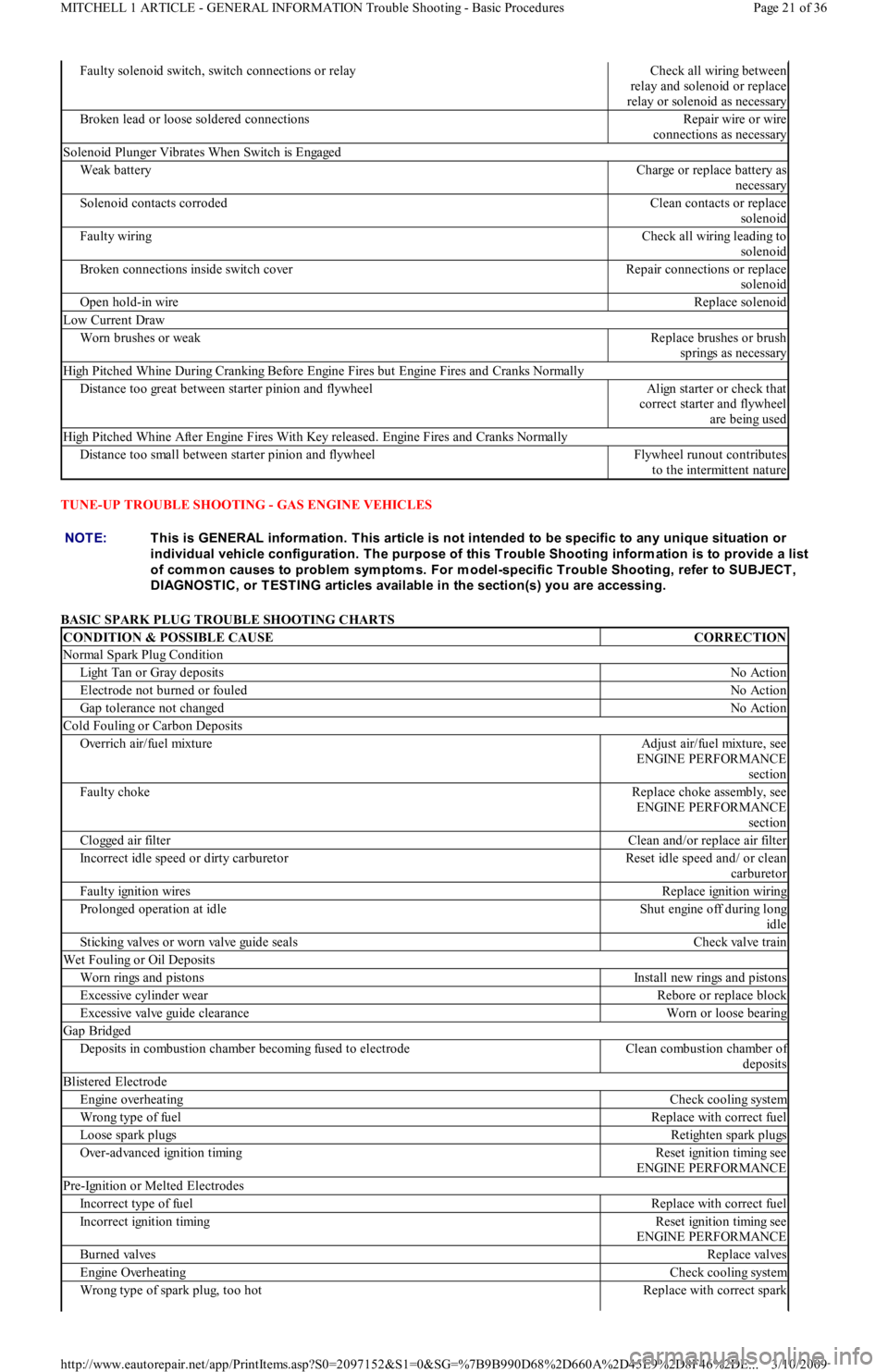
TUNE-UP TROUBLE SHOOTING - GAS ENGINE VEHICLES
BASIC SPARK PLUG TROUBLE SHOOTING CHARTS
Faulty solenoid switch, switch connections or relayCheck all wiring between
relay and solenoid or replace
relay or solenoid as necessary
Broken lead or loose soldered connectionsRepair wire or wire
connections as necessary
Solenoid Plunger Vibrates When Switch is Engaged
Weak batteryCharge or replace battery as
necessary
Solenoid contacts corrodedClean contacts or replace
solenoid
Faulty wiringCheck all wiring leading to
solenoid
Broken connections inside switch coverRepair connections or replace
solenoid
Open hold-in wireReplace solenoid
Low Current Draw
Worn brushes or weakReplace brushes or brush
springs as necessary
High Pitched Whine During Cranking Before Engine Fires but Engine Fires and Cranks Normally
Distance too great between starter pinion and flywheelAlign starter or check that
correct starter and flywheel
are being used
High Pitched Whine After Engine Fires With Key released. Engine Fires and Cranks Normally
Distance too small between starter pinion and flywheelFlywheel runout contributes
to the intermittent nature
NOTE:This is GENERAL inform ation. This article is not intended to be specific to any unique situation or
individual vehicle configuration. T he purpose of this T rouble Shooting inform ation is to provide a list
of com m on causes to problem sym ptom s. For m odel-specific T rouble Shooting, refer to SUBJECT ,
DIAGNOST IC, or T EST ING articles available in the section(s) you are accessing.
CONDITION & POSSIBLE CAUSECORRECTION
Normal Spark Plug Condition
Light Tan or Gray depositsNo Action
Electrode not burned or fouledNo Action
Gap tolerance not changedNo Action
Cold Fouling or Carbon Deposits
Overrich air/fuel mixtureAdjust air/fuel mixture, see
ENGINE PERFORMANCE
section
Faulty chokeReplace choke assembly, see
ENGINE PERFORMANCE
section
Clogged air filterClean and/or replace air filter
Incorrect idle speed or dirty carburetorReset idle speed and/ or clean
carburetor
Faulty ignition wiresReplace ignition wiring
Prolonged operation at idleShut engine off during long
idle
Sticking valves or worn valve guide sealsCheck valve train
Wet Fouling or Oil Deposits
Worn rings and pistonsInstall new rings and pistons
Excessive cylinder wearRebore or replace block
Excessive valve guide clearanceWorn or loose bearing
Gap Bridged
Deposits in combustion chamber becoming fused to electrodeClean combustion chamber of
deposits
Blistered Electrode
Engine overheatingCheck cooling system
Wrong type of fuelReplace with correct fuel
Loose spark plugsRetighten spark plugs
Over-advanced ignition timingReset ignition timing see
ENGINE PERFORMANCE
Pre-Ignition or Melted Electrodes
Incorrect type of fuelReplace with correct fuel
Incorrect ignition timingReset ignition timing see
ENGINE PERFORMANCE
Burned valvesReplace valves
Engine OverheatingCheck cooling system
Wrong type of spark plug, too hotReplace with correct spark
Page 21 of 36 MITCHELL 1 ARTICLE - GENERAL INFORMATION Trouble Shooting - Basic Procedures
3/10/2009 http://www.eautorepair.net/app/PrintItems.asp?S0=2097152&S1=0&SG=%7B9B990D68%2D660A%2D45E9%2D8F46%2DE
...
Page 241 of 454
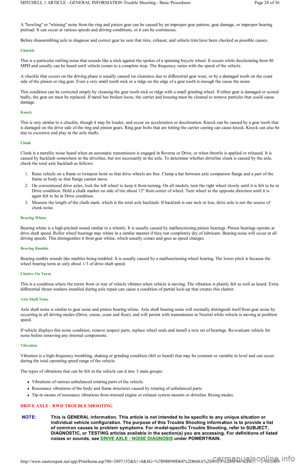
A "howling" or "whining" noise from the ring and pinion gear can be caused by an improper gear pattern, gear damage, or improper bearing
preload. It can occur at various speeds and driving conditions, or it can be continuous.
Before disassembling axle to diagnose and correct gear ke sure that tires, exhaust, and vehicle trim have been checked as possible causes.
Chuckle
This is a particular rattling noise that sounds like a stick against the spokes of a spinning bicycle wheel. It occurs while decelerating from 40
MPH and usually can be heard until vehicle comes to a complete stop. The frequency varies with the speed of the vehicle.
A chuckle that occurs on the driving phase is usually caused ive clearance due to differential gear wear, or by a damaged tooth on the coast
side of the pinion or ring gear. Even a very small tooth nick or a ridge on the edge of a gear tooth is enough the cause the noise.
This condition can be corrected simply by cleaning the gear tooth nick or ridge with a small grinding wheel. If either gear is damaged or scored
badly, the gear set must be replaced. If metal has broken loose, the carrier and housing must be cleaned to remove particles that could cause
damage.
Knock
This is very similar to a chuckle, though it may be louder, and occur on acceleration or deceleration. Knock can be caused by a gear tooth that
is damaged on the drive side of the ring and pinion gears. Ring gear bolts that are hitting the carrier casting can cause knock. Knock can also be
due to excessive end play in the axle shafts.
Clunk
Clunk is a metallic noise heard when an automatic transmission is engaged in Reverse or Drive, or when throttle is applied or released. It is
caused by backlash somewhere in the driveline, but not necessarily in the axle. To determine whether driveline clunk is caused by the axle,
check the total axle backlash as follows:
1. Raise vehicle on a frame or twinpost hoist so that drive wheels are free. Clamp a bar between axle companion flange and a part of the
frame or body so that flange cannot move.
2. On conventional drive axles, lock the left wheel to keep it from turning. On all models, turn the right wheel slowly until it is felt to be in
Drive condition. Hold a chalk marker on side of tire about 12" from center of wheel. Turn wheel in the opposite direction until it is
again felt to be in Drive condition.
3. Measure the length of the chalk mark, which is the total axle backlash. If backlash is one inch or less, drive axle is not the source of
clunk noise.
Bearing Whine
Bearing whine is a high-pitched sound similar to a whistle. It is usually caused by malfunctioning pinion bearings. Pinion bearings operate at
drive shaft speed. Roller wheel bearings may whine in a similar manner if they run completely dry of lubricant. Bearing noise will occur at all
driving speeds. This distinguishes it from gear whine, which usually comes and goes as speed changes.
Bearing Rumble
Bearing rumble sounds like marbles being tumbled. It is usually caused by a malfunctioning wheel bearing. The lower pitch is because the
wheel bearing turns at only about 1/3 of drive shaft speed.
Chatter On Turns
This is a condition where the entire front or rear of vehicle vibrates when vehicle is moving. The vibration is plainly felt as well as heard. Extra
differential thrust washers installed during axle repair can cause a condition of partial lock-up that creates this chatter.
Axle Shaft Noise
Axle shaft noise is similar to gear noise and pinion bearing whine. Axle shaft bearing noise will normally distinguish itself from gear noise by
occurring in all driving modes (Drive, cruise, coast and float), and will persist with transmission in Neutral while vehicle is moving at problem
speed.
If vehicle displays this noise condition, remove suspect parts, replace wheel seals and install a new set of bearings. Re-evaluate vehicle for
noise before removing any internal components.
Vibration
Vibration is a high-frequency trembling, shaking or grinding condition (felt or heard) that may be constant or variable in level and can occur
during the total operating speed range of the vehicle.
The types of vibrations that can be felt in the vehicle can d into 3 main groups:
Vibrations of various unbalanced rotating parts of the vehicle.
Resonance vibrations of the body and frame structures caused by rotating of unbalanced parts.
Tip-in moans of resonance vibrations from stressed engine or exhaust system mounts or driveline flexing modes.
DRIVE AXLE - RWD TROUBLE SHOOTING
NOTE:This is GENERAL inform ation. This article is not intended to be specific to any unique situation or
individual vehicle configuration. T he purpose of this T rouble Shooting inform ation is to provide a list
of com m on causes to problem sym ptom s. For m odel-specific T rouble Shooting, refer to SUBJECT ,
DIAGNOST IC, or T EST ING articles available in the section(s) you are accessing. For definitions of listed
noises or sounds, see DRIVE AXLE
- NOISE DIAGNOSIS under POWERTRAIN.
Page 28 of 36 MITCHELL 1 ARTICLE - GENERAL INFORMATION Trouble Shooting - Basic Procedures
3/10/2009 http://www.eautorepair.net/app/PrintItems.asp?S0=2097152&S1=0&SG=%7B9B990D68%2D660A%2D45E9%2D8F46%2DE
...
Page 242 of 454
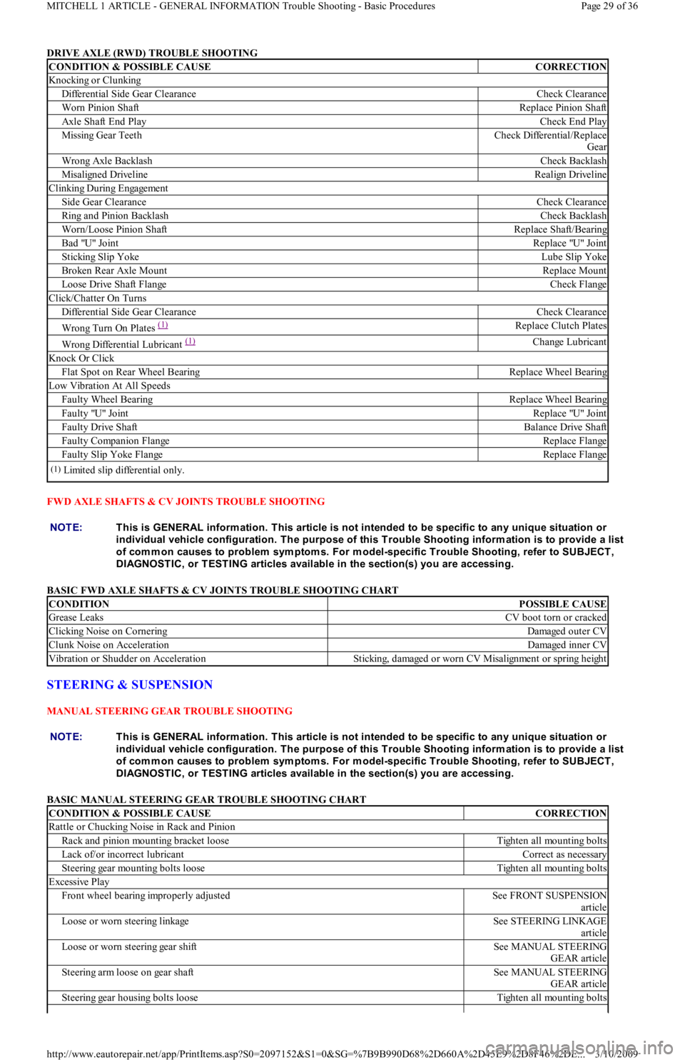
DRIVE AXLE (RWD) TROUBLE SHOOTING
FWD AXLE SHAFTS & CV JOINTS TROUBLE SHOOTING
BASIC FWD AXLE SHAFTS & CV JOINTS TROUBLE SHOOTING CHART
STEERING & SUSPENSION
MANUAL STEERING GEAR TROUBLE SHOOTING
BASIC MANUAL STEERING GEAR TROUBLE SHOOTING CHART
CONDITION & POSSIBLE CAUSECORRECTION
Knocking or Clunking
Differential Side Gear ClearanceCheck Clearance
Worn Pinion ShaftReplace Pinion Shaft
Axle Shaft End PlayCheck End Play
Missing Gear TeethCheck Differential/Replace
Gear
Wrong Axle BacklashCheck Backlash
Misaligned DrivelineRealign Driveline
Clinking During Engagement
Side Gear ClearanceCheck Clearance
Ring and Pinion BacklashCheck Backlash
Worn/Loose Pinion ShaftReplace Shaft/Bearing
Bad "U" JointReplace "U" Joint
Sticking Slip YokeLube Slip Yoke
Broken Rear Axle MountReplace Mount
Loose Drive Shaft FlangeCheck Flange
Click/Chatter On Turns
Differential Side Gear ClearanceCheck Clearance
Wrong Turn On Plates (1)Replace Clutch Plates
Wrong Differential Lubricant (1)Change Lubricant
Knock Or Click
Flat Spot on Rear Wheel BearingReplace Wheel Bearing
Low Vibration At All Speeds
Faulty Wheel BearingReplace Wheel Bearing
Faulty "U" JointReplace "U" Joint
Faulty Drive ShaftBalance Drive Shaft
Faulty Companion FlangeReplace Flange
Faulty Slip Yoke FlangeReplace Flange
(1)Limited slip differential only.
NOTE:This is GENERAL inform ation. This article is not intended to be specific to any unique situation or
individual vehicle configuration. T he purpose of this T rouble Shooting inform ation is to provide a list
of com m on causes to problem sym ptom s. For m odel-specific T rouble Shooting, refer to SUBJECT ,
DIAGNOST IC, or T EST ING articles available in the section(s) you are accessing.
CONDITIONPOSSIBLE CAUSE
Grease LeaksCV boot torn or cracked
Clicking Noise on CorneringDamaged outer CV
Clunk Noise on AccelerationDamaged inner CV
Vibration or Shudder on AccelerationSticking, damaged or worn CV Misalignment or spring height
NOTE:This is GENERAL inform ation. This article is not intended to be specific to any unique situation or
individual vehicle configuration. T he purpose of this T rouble Shooting inform ation is to provide a list
of com m on causes to problem sym ptom s. For m odel-specific T rouble Shooting, refer to SUBJECT ,
DIAGNOST IC, or T EST ING articles available in the section(s) you are accessing.
CONDITION & POSSIBLE CAUSECORRECTION
Rattle or Chucking Noise in Rack and Pinion
Rack and pinion mounting bracket looseTighten all mounting bolts
Lack of/or incorrect lubricantCorrect as necessary
Steering gear mounting bolts looseTighten all mounting bolts
Excessive Play
Front wheel bearing improperly adjustedSee FRONT SUSPENSION
article
Loose or worn steering linkageSee STEERING LINKAGE
article
Loose or worn steering gear shiftSee MANUAL STEERING
GEAR article
Steering arm loose on gear shaftSee MANUAL STEERING
GEAR article
Steering gear housing bolts looseTighten all mounting bolts
Page 29 of 36 MITCHELL 1 ARTICLE - GENERAL INFORMATION Trouble Shooting - Basic Procedures
3/10/2009 http://www.eautorepair.net/app/PrintItems.asp?S0=2097152&S1=0&SG=%7B9B990D68%2D660A%2D45E9%2D8F46%2DE
...
Page 254 of 454
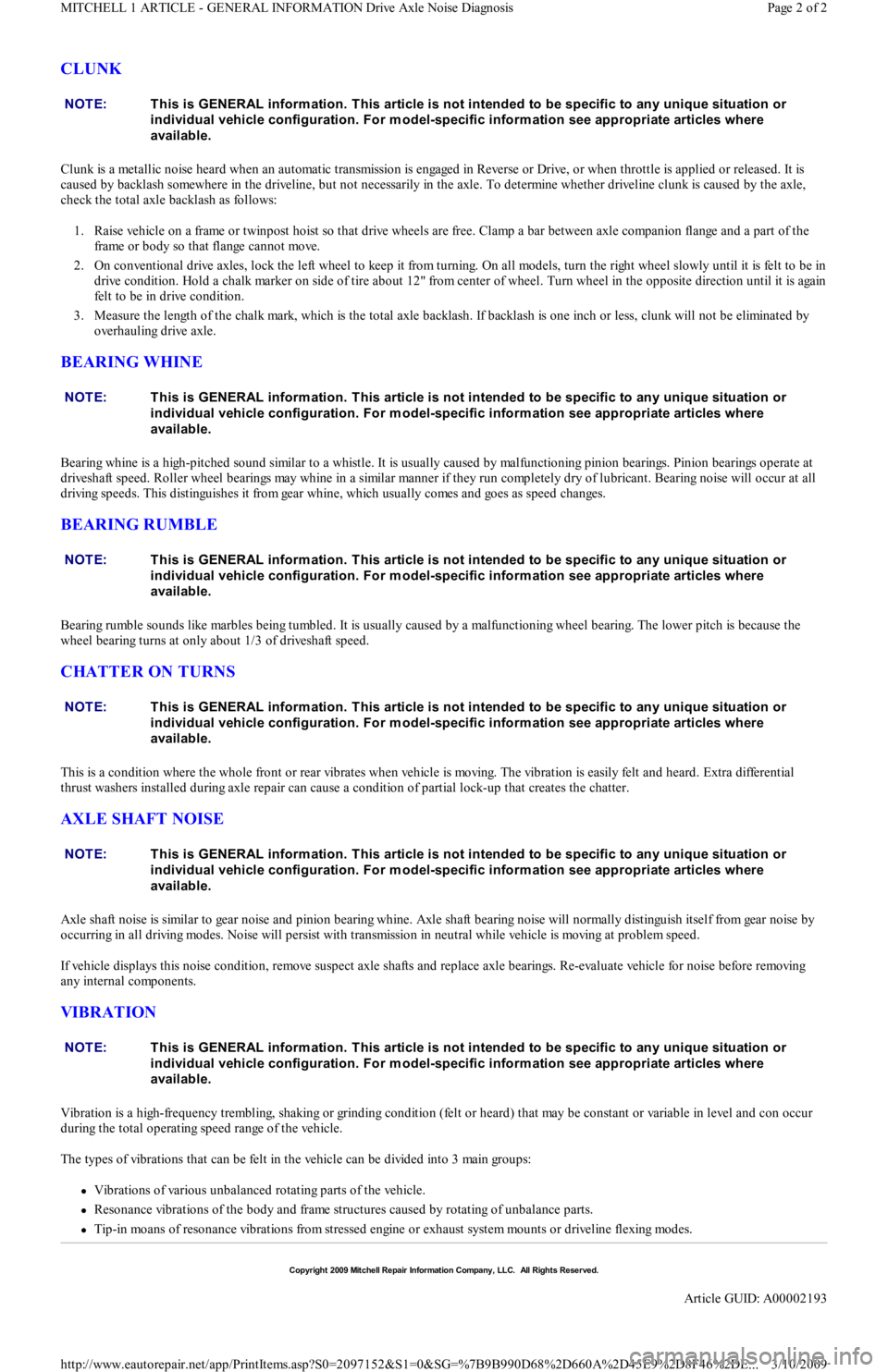
CLUNK
Clunk is a metallic noise heard when an automatic transmission is engaged in Reverse or Drive, or when throttle is applied or released. It is
caused by backlash somewhere in the driveline, but not necessarily in the axle. To determine whether driveline clunk is caused by the axle,
check the total axle backlash as follows:
1. Raise vehicle on a frame or twinpost hoist so that drive wheels are free. Clamp a bar between axle companion flange and a part of the
frame or body so that flange cannot move.
2. On conventional drive axles, lock the left wheel to keep it from turning. On all models, turn the right wheel slowly until it is felt to be in
drive condition. Hold a chalk marker on side of tire about 12" from center of wheel. Turn wheel in the opposite direction until it is again
felt to be in drive condition.
3. Measure the length of the chalk mark, which is the total axle backlash. If backlash is one inch or less, clunk will not be eliminated by
overhauling drive axle.
BEARING WHINE
Bearing whine is a high-pitched sound similar to a whistle. It is usually caused by malfunctioning pinion bearings. Pinion bearings operate at
driveshaft speed. Roller wheel bearings may whine in a similar manner if they run completely dry of lubricant. Bearing noise will occur at all
driving speeds. This distinguishes it from gear whine, which usually comes and goes as speed changes.
BEARING RUMBLE
Bearing rumble sounds like marbles being tumbled. It is usually caused by a malfunctioning wheel bearing. The lower pitch is because the
wheel bearing turns at only about 1/3 of driveshaft speed.
CHATTER ON TURNS
This is a condition where the whole front or rear vibrates when vehicle is moving. The vibration is easily felt and heard. Extra differential
thrust washers installed during axle repair can cause a condition of partial lock-up that creates the chatter.
AXLE SHAFT NOISE
Axle shaft noise is similar to gear noise and pinion bearing whine. Axle shaft bearing noise will normally distinguish itself from gear noise by
occurring in all driving modes. Noise will persist with transmission in neutral while vehicle is moving at problem speed.
If vehicle displays this noise condition, remove suspect axle shafts and replace axle bearings. Re-evaluate vehicle for noise before removing
any internal components.
VIB R AT ION
Vibration is a high-frequency trembling, shaking or grinding condition (felt or heard) that may be constant or variable in level and con occur
during the total operating speed range of the vehicle.
The types of vibrations that can be felt in the vehicle can be divided into 3 main groups:
Vibrations of various unbalanced rotating parts of the vehicle.
Resonance vibrations of the body and frame structures caused by rotating of unbalance parts.
Tip-in moans of resonance vibrations from stressed engine or exhaust system mounts or driveline flexing modes. NOTE:This is GENERAL inform ation. This article is not intended to be specific to any unique situation or
individual vehicle configuration. For m odel-specific inform ation see appropriate articles where
available.
NOTE:This is GENERAL inform ation. This article is not intended to be specific to any unique situation or
individual vehicle configuration. For m odel-specific inform ation see appropriate articles where
available.
NOTE:This is GENERAL inform ation. This article is not intended to be specific to any unique situation or
individual vehicle configuration. For m odel-specific inform ation see appropriate articles where
available.
NOTE:This is GENERAL inform ation. This article is not intended to be specific to any unique situation or
individual vehicle configuration. For m odel-specific inform ation see appropriate articles where
available.
NOTE:This is GENERAL inform ation. This article is not intended to be specific to any unique situation or
individual vehicle configuration. For m odel-specific inform ation see appropriate articles where
available.
NOTE:This is GENERAL inform ation. This article is not intended to be specific to any unique situation or
individual vehicle configuration. For m odel-specific inform ation see appropriate articles where
available.
Copyr ight 2009 Mitchell Repair Information Company, LLC. All Rights Reserved.
Article GUID: A00002193
Page 2 of 2 MITCHELL 1 ARTICLE - GENERAL INFORMATION Drive Axle Noise Diagnosis
3/10/2009 http://www.eautorepair.net/app/PrintItems.asp?S0=2097152&S1=0&SG=%7B9B990D68%2D660A%2D45E9%2D8F46%2DE
...