1991 FORD FESTIVA ground clearance
[x] Cancel search: ground clearancePage 101 of 454
Back To Article
ENGINE OVERHAUL
1991-92 FORD MOT OR CO. ENGINES 1.3L & 1.6L 4-Cylinder
ENGINE IDENTIFICATION
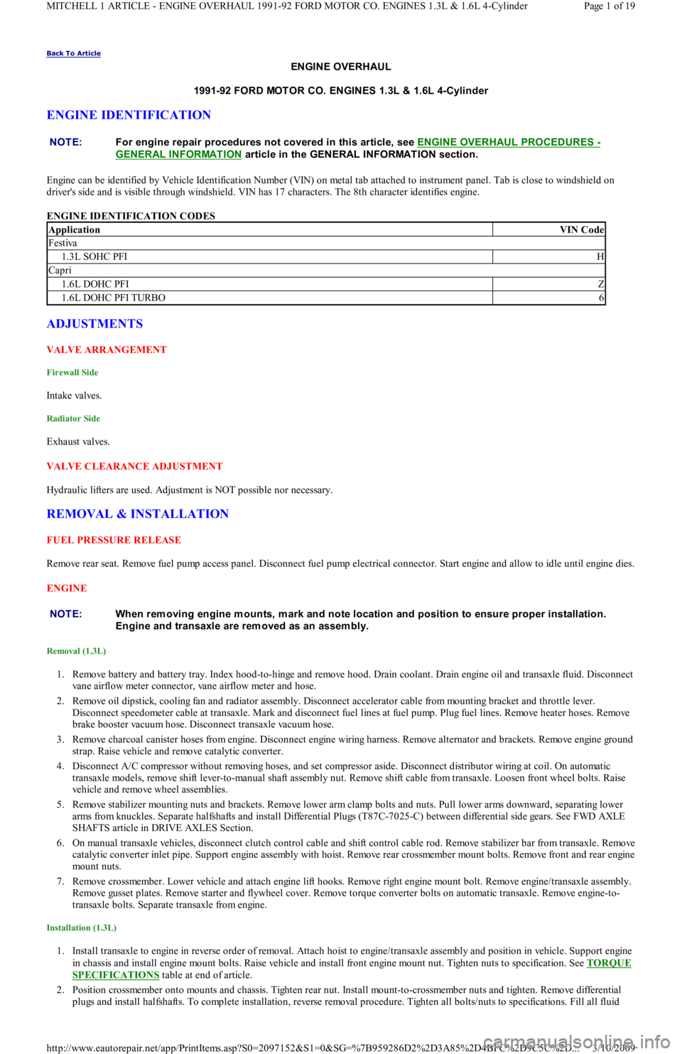
Engine can be identified by Vehicle Identification Number (VIN) on metal tab attached to instrument panel. Tab is close to windshield on
driver's side and is visible through windshield. VIN has 17 characters. The 8th character identifies engine.
ENGINE IDENTIFICATION CODES
ADJUSTMENTS
VALVE ARRANGEMENT
Firewall Side
In t ake val ves.
Radiator Side
Exhaust valves.
VALVE CLEARANCE ADJUSTMENT
Hydraulic lifters are used. Adjustment is NOT possible nor necessary.
REMOVAL & INSTALLATION
FUEL PRESSURE RELEASE
Remove rear seat. Remove fuel pump access panel. Disconnect fuel pump electrical connector. Start engine and allow to idle until engine dies.
ENGINE
Removal (1.3L)
1. Remove battery and battery tray. Index hood-to-hinge and remove hood. Drain coolant. Drain engine oil and transaxle fluid. Disconnect
vane airflow meter connector, vane airflow meter and hose.
2. Remove oil dipstick, cooling fan and radiator assembly. Disconnect accelerator cable from mounting bracket and throttle lever.
Disconnect speedometer cable at transaxle. Mark and disconnect fuel lines at fuel pump. Plug fuel lines. Remove heater hoses. Remove
brake booster vacuum hose. Disconnect transaxle vacuum hose.
3. Remove charcoal canister hoses from engine. Disconnect engine wiring harness. Remove alternator and brackets. Remove engine ground
strap. Raise vehicle and remove catalytic converter.
4. Disconnect A/C compressor without removing hoses, and set compressor aside. Disconnect distributor wiring at coil. On automatic
transaxle models, remove shift lever-to-manual shaft assembly nut. Remove shift cable from transaxle. Loosen front wheel bolts. Raise
vehicle and remove wheel assemblies.
5. Remove stabilizer mounting nuts and brackets. Remove lower arm clamp bolts and nuts. Pull lower arms downward, separating lower
arms from knuckles. Separate halfshafts and install Differential Plugs (T87C-7025-C) between differential side gears. See FWD AXLE
SHAFTS article in DRIVE AXLES Section.
6. On manual transaxle vehicles, disconnect clutch control cable and shift control cable rod. Remove stabilizer bar from transaxle. Remove
catalytic converter inlet pipe. Support engine assembly with hoist. Remove rear crossmember mount bolts. Remove front and rear engine
mount nuts.
7. Remove crossmember. Lower vehicle and attach engine lift hooks. Remove right engine mount bolt. Remove engine/transaxle assembly.
Remove gusset plates. Remove starter and flywheel cover. Remove torque converter bolts on automatic transaxle. Remove engine-to-
transaxle bolts. Separate transaxle from engine.
Installation (1.3L)
1. Install transaxle to engine in reverse order of removal. Attach hoist to engine/transaxle assembly and position in vehicle. Support engine
in chassis and install engine mount bolts. Raise vehicle and install front engine mount nut. Tighten nuts to specification. See TORQUE
SPECIFICATIONS table at end of article.
2. Position crossmember onto mounts and chassis. Tighten rear nut. Install mount-to-crossmember nuts and tighten. Remove differential
plugs and install halfshafts. To complete installation, reverse removal procedure. Tighten all bolts/nuts to specifications. Fill all fluid NOTE:For engine repair procedures not covered in this article, see ENGINE OVERHAUL PROCEDURES
-
GENERAL INFORMATION
article in the GENERAL INFORMAT ION section.
ApplicationVIN Code
Festiva
1.3L SOHC PFIH
Capri
1.6L DOHC PFIZ
1.6L DOHC PFI TURBO6
NOTE:When rem oving engine m ounts, m ark and note location and position to ensure proper installation.
Engine and transaxle are rem oved as an assem bly.
Page 1 of 19 MITCHELL 1 ARTICLE - ENGINE OVERHAUL 1991-92 FORD MOTOR CO. ENGINES 1.3L & 1.6L 4-Cylinder
3/10/2009 http://www.eautorepair.net/app/PrintItems.asp?S0=2097152&S1=0&SG=%7B959286D2%2D3A85%2D4BFC%2D9C5C%2D
...
Page 108 of 454
front oil seal. Carefully slide camshaft out front of cylinder head. DO NOT d a ma ge b e a r in g b o r e s.
Inspection (1.3L)
1. Check cylinder head for warpage. See INSPECTION under CYLINDER HEAD under REMOVAL & INSTALLATION. Measure
camshaft lobes across their maximum dimensions. Inspect for scoring and wear. Replace camshaft if not within specification. See, in this
article, CAMSHAFT LOBE SPECIFICATIONS
table.
2. Measure camshaft bearing journals and cylinder head bores. See Fig. 6
and Fig. 7 . Subtract camshaft bearing journal O.D. from
cylinder head bore I.D. to obtain oil clearance. If clearance is not within specification, replace head and/or camshaft. See, in this article,
CAMSHAFT SPECIFICATIONS
table under ENGINE SPECIFICATIONS tables.
Installation (1.3L)
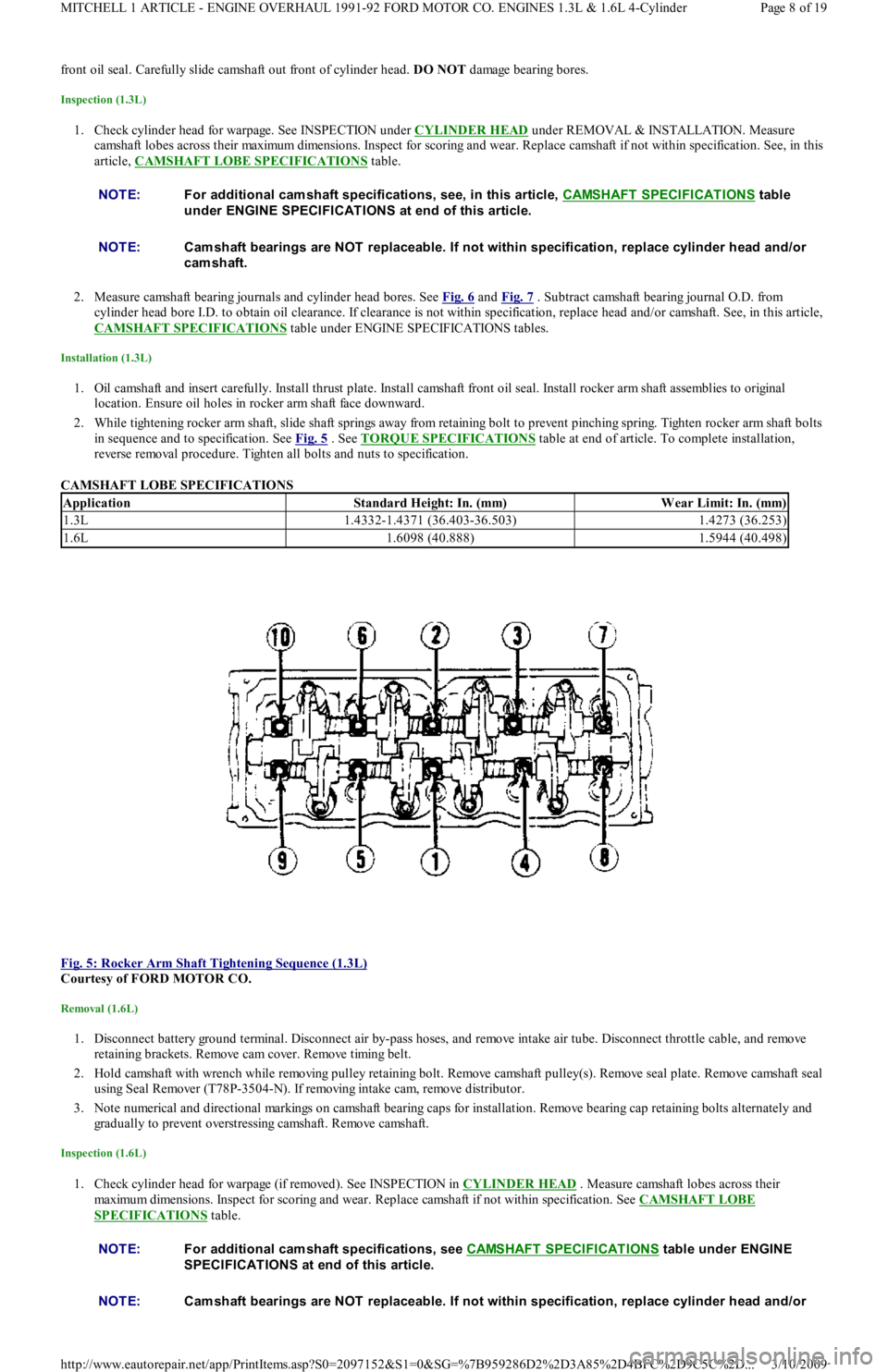
1. Oil camshaft and insert carefully. Install thrust plate. Install camshaft front oil seal. Install rocker arm shaft assemblies to original
location. Ensure oil holes in rocker arm shaft face downward.
2. While tightening rocker arm shaft, slide shaft springs away from retaining bolt to prevent pinching spring. Tighten rocker arm shaft bolts
in sequence and to specification. See Fig. 5
. See TORQUE SPECIFICATIONS table at end of article. To complete installation,
reverse removal procedure. Tighten all bolts and nuts to specification.
CAMSHAFT LOBE SPECIFICATIONS
Fig. 5: Rocker Arm Shaft Tightening Sequence (1.3L)
Courtesy of FORD MOTOR CO.
Removal (1.6L)
1. Disconnect battery ground terminal. Disconnect air by-pass hoses, and remove intake air tube. Disconnect throttle cable, and remove
ret ain in g b racket s. Remo ve cam co ver. Remo ve t imin g b el t .
2. Hold camshaft with wrench while removing pulley retaining bolt. Remove camshaft pulley(s). Remove seal plate. Remove camshaft seal
using Seal Remover (T78P-3504-N). If removing intake cam, remove distributor.
3. Note numerical and directional markings on camshaft bearing caps for installation. Remove bearing cap retaining bolts alternately and
gradually to prevent overstressing camshaft. Remove camshaft.
Inspection (1.6L)
1. Check cylinder head for warpage (if removed). See INSPECTION in CYLINDER HEAD . Measure camshaft lobes across their
maximum dimensions. Inspect for scoring and wear. Replace camshaft if not within specification. See CAMSHAFT LOBE
SPECIFICATIONS table. NOTE:For additional cam shaft specifications, see, in this article, CAMSHAFT SPECIFICAT IONS
table
under ENGINE SPECIFICATIONS at end of this article.
NOTE:Cam shaft bearings are NOT replaceable. If not within specification, replace cylinder head and/or
cam shaft.
ApplicationStandard Height: In. (mm)W ear Limit: In. (mm)
1.3L1.4332-1.4371 (36.403-36.503)1.4273 (36.253)
1.6L1.6098 (40.888)1.5944 (40.498)
NOTE:For additional cam shaft specifications, see CAMSHAFT SPECIFICAT IONS table under ENGINE
SPECIFICAT IONS at end of this article.
NOTE:Cam shaft bearings are NOT replaceable. If not within specification, replace cylinder head and/or
Page 8 of 19 MITCHELL 1 ARTICLE - ENGINE OVERHAUL 1991-92 FORD MOTOR CO. ENGINES 1.3L & 1.6L 4-Cylinder
3/10/2009 http://www.eautorepair.net/app/PrintItems.asp?S0=2097152&S1=0&SG=%7B959286D2%2D3A85%2D4BFC%2D9C5C%2D
...
Page 109 of 454
2. Measure camshaft bearing journals and cylinder head bores (with bearing caps in place and torqued to specification). See Fig. 7 .
Subtract camshaft bearing journal O.D. from cylinder head bore I.D. to obtain oil clearance. If clearance is not within specification,
replace head and/or camshaft. See CAMSHAFT SPECIFICATIONS
table under ENGINE SPECIFICATIONS at end of article.
Installation (1.6L)
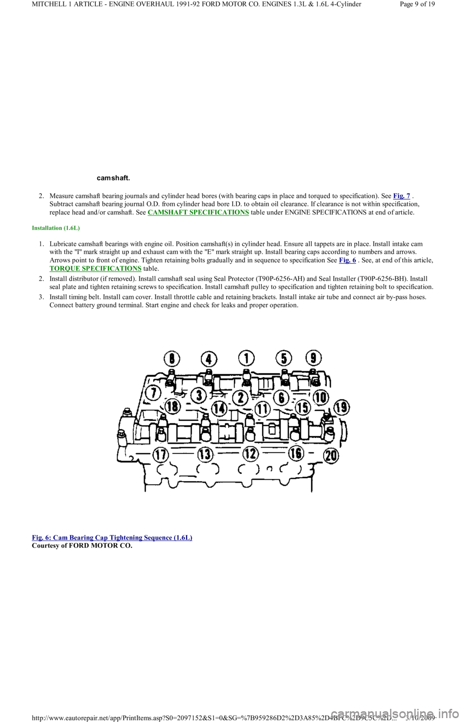
1. Lubricate camshaft bearings with engine oil. Position camshaft(s) in cylinder head. Ensure all tappets are in place. Install intake cam
with the "I" mark straight up and exhaust cam with the "E" mark straight up. Install bearing caps according to numbers and arrows.
Arrows point to front of engine. Tighten retaining bolts gradually and in sequence to specification See Fig. 6
. See, at end of this article,
TORQUE SPECIFICATIONS
table.
2. Install distributor (if removed). Install camshaft seal using Seal Protector (T90P-6256-AH) and Seal Installer (T90P-6256-BH). Install
seal plate and tighten retaining screws to specification. Install camshaft pulley to specification and tighten retaining bolt to specification.
3. Install timing belt. Install cam cover. Install throttle cable and retaining brackets. Install intake air tube and connect air by-pass hoses.
Connect battery ground terminal. Start engine and check for leaks and proper operation.
Fig. 6: Cam Bearing Cap Tightening Sequence (1.6L)
Courtesy of FORD MOTOR CO. cam shaft.
Page 9 of 19 MITCHELL 1 ARTICLE - ENGINE OVERHAUL 1991-92 FORD MOTOR CO. ENGINES 1.3L & 1.6L 4-Cylinder
3/10/2009 http://www.eautorepair.net/app/PrintItems.asp?S0=2097152&S1=0&SG=%7B959286D2%2D3A85%2D4BFC%2D9C5C%2D
...
Page 111 of 454
bearing oil seal. To complete installation, reverse removal procedure.
WATER PUMP
Removal & Installation (1.3L)
Remove timing belt. Drain cooling system. Remove lower radiator hose and heater return hose from water pump. Remove water pump
retaining bolts and water pump. Clean gasket mounting surface and replace gasket. To install, reverse removal procedure.
Removal (1.6L)
1. Remove timing belt. See TIMING BELT . Drain cooling system. Remove timing belt tensioner and idler pulleys. Remove oil dipstick
bracket retaining bolt.
2. Remove power steering pump from retaining bracket, leaving hoses attached. Remove power steering bracket and position power
steering pump to one side. Remove water pump outlet. Remove water pump retaining bolts and water pump.
Installation (1.6L)
1. Clean all gasket surfaces. Transfer rubber belt cover seal to new water pump (if required). Position water pump with new gasket and
install retaining bolts. Install pump outlet with new gasket and "O" ring. See TORQUE SPECIFICATIONS
table at end of article.
2. Install oil dipstick retaining bolt. Install timing belt tensioner and idler pulleys. Install power steering pump bracket. Install power
steering pump. Tighten all bolts and nuts to specification. See TORQUE SPECIFICATIONS
table at end of article.
3. Install timing belt. Fill cooling system. Start engine and check for leaks and proper system function.
OIL PAN
Removal (1.3L)
Disconnect battery ground cable. Raise vehicle and drain engine oil. Remove flywheel housing dust cover. Remove oil pan retaining bolts,
nuts and stiffeners. Rotate crankshaft while removing oil pan. Remove baffle plate from oil pan. Clean gasket mating surfaces thoroughly.
Installation (1.3L)
Ensure gasket surfaces are clean. Apply oil resistant sealer to front and rear engine covers and across joint line of cylinder block.
Removal (1.6L)
1. Raise vehicle and drain engine oil. Remove frame brace retaining bolt. Loosen RH "A" arm front bolt, and pivot brace downward.
Disconnect front exhaust pipe from exhaust manifold (or turbocharger). Remove exhaust pipe bracket retaining bolts. Loosen rubber
exhaust hangers at catalytic converter.
2. Allow exhaust to hang supported by mechanic's wire. Disconnect turbocharger oil return hose (if equipped). Remove oil pan retaining
bolts. Carefully pry oil pan loose from cylinder block.
Installation (1.6L)
1. Clean pan and block gasket surfaces. Apply Gasket Sealant (E3AZ-19562-A) to new front and rear pan seals. Install seals to cylinder
block. Apply Gasket Sealant (E3AZ-19562-A) to oil pan gasket surface. See Fig. 8
. Install oil pan and tighten pan retaining bolts to
specification. See TORQUE SPECIFICATIONS
table at end of article.
2. Connect turbocharger oil return hose (if equipped). Install rubber exhaust hanger to brackets. Install new gasket and connect fro n t
exhaust pipe to exhaust manifold (or turbocharger). Install front exhaust pipe bracket. Tighten nuts and bolts to specification.
3. Pivot frame brace into position. Tighten retaining bolt to crossmember and RH "A" arm front retaining bolt to specification. Lower
vehicle, fill with oil and start engine. Check for oil leaks and system operation. NOTE:Raise engine slightly with floor jack, if required, to gain clearance for water pum p rem oval.
CAUT ION: DO NOT force a pry tool between cylinder block and oil pan.
Page 11 of 19 MITCHELL 1 ARTICLE - ENGINE OVERHAUL 1991-92 FORD MOTOR CO. ENGINES 1.3L & 1.6L 4-Cylinder
3/10/2009 http://www.eautorepair.net/app/PrintItems.asp?S0=2097152&S1=0&SG=%7B959286D2%2D3A85%2D4BFC%2D9C5C%2D
...
Page 129 of 454
Back To Article
D - ADJUSTMENTS
1991 ENGINE PERFORMANCE Ford/Mercury - On-Vehicle Adjustm ents
ADJUSTMENTS
ENGINE MECHANICAL
Before beginning any on-vehicle adjustments to fuel or ignition systems, ensure engine mechanical condition is okay.
VALVE CLEARANCE
IGNITION TIMING
CAPRI
1. Place automatic transmission in Park or manual transmission in Neutral. Disconnect and plug hoses attached to vacuum diaphragm
assembly on distributor. Connect tachometer and timing light. Turn off all electrical loads.
2. Start engine, and warm it to operating temperature. Ensure idle speed is set to specification, adjusting if necessary. See IDLE SPEED &
MIXTURE . Determine initial timing. See IGNITION TIMING table. If base timing is not correct, loosen distributor mounting bolts
and rotate distributor until marks align. Tighten bolts to 14-18 ft. lbs. (19-25 N.m).
3. Increase engine RPM while observing timing light. Verify ignition timing advances. For Turbo models, go to step 5). For non-Turbo
models, continue with step 4).
4. On non-Turbo models, apply 16 in. Hg vacuum to chamber "A". Verify timing advances by 26-30 degrees. Remove vacuum source from
chamber "A". Apply 8 in. Hg vacuum to chamber "B" while observing timing. Verify timing advances by 3-7 degrees. Stop engine, and
remove test equipment.
5. On Turbo models, apply 20 in. Hg vacuum to advance diaphragm. Verify timing advances by 13-17 degrees. Disconnect vacuum source.
Apply 8 psi (.6 kg/cm
2 ) pressure to advance diaphragm. Verify timing retards by 3-7 degrees. Stop engine, and remove test equipment.
FESTIVA
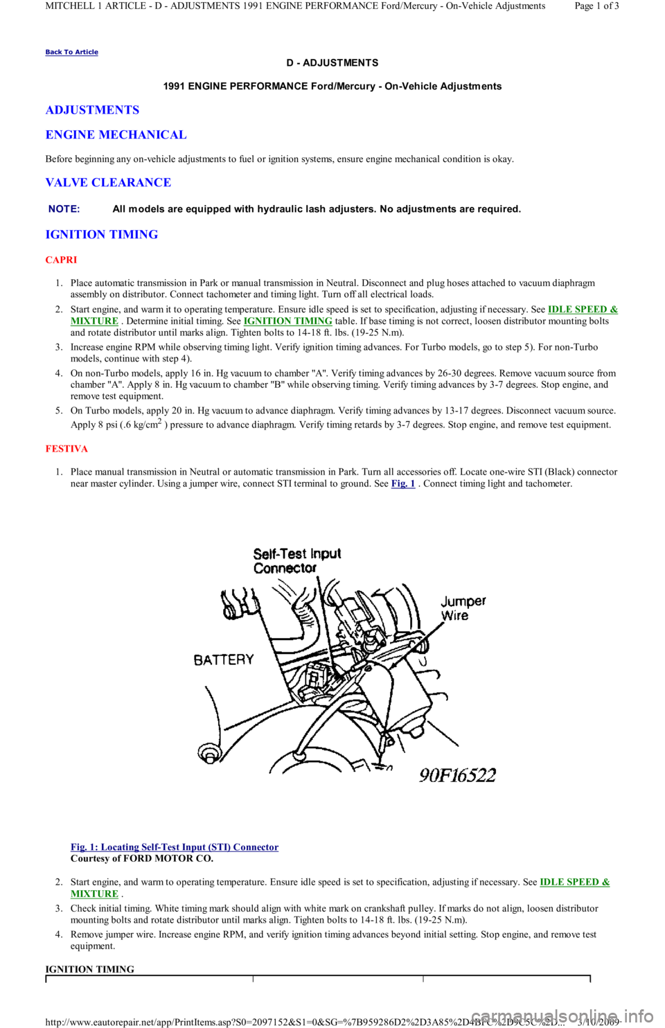
1. Place manual transmission in Neutral or automatic transmission in Park. Turn all accessories off. Locate one-wire STI (Black) connector
near master cylinder. Using a jumper wire, connect STI terminal to ground. See Fig. 1
. Connect timing light and tachometer.
Fig. 1: Locating Self
-Test Input (STI) Connector
Courtesy of FORD MOTOR CO.
2. Start engine, and warm to operating temperature. Ensure idle speed is set to specification, adjusting if necessary. See IDLE SPEED &
MIXTURE .
3. Check initial timing. White timing mark should align with white mark on crankshaft pulley. If marks do not align, loosen distributor
mounting bolts and rotate distributor until marks align. Tighten bolts to 14-18 ft. lbs. (19-25 N.m).
4. Remove jumper wire. Increase engine RPM, and verify ignition timing advances beyond initial setting. Stop engine, and remove test
equipment.
IGNITION TIMING NOTE:All m odels are equipped with hydraulic lash adjusters. No adjustm ents are required.
Page 1 of 3 MITCHELL 1 ARTICLE - D - ADJUSTMENTS 1991 ENGINE PERFORMANCE Ford/Mercury - On-Vehicle Adjustments
3/10/2009 http://www.eautorepair.net/app/PrintItems.asp?S0=2097152&S1=0&SG=%7B959286D2%2D3A85%2D4BFC%2D9C5C%2D
...
Page 218 of 454
Broken clutch housingSee STARTER article
Pinion shaft rusted or drySee STARTER article
Engine basic timing incorrectSee Ignition Timing in TUNE-
UP article
Broken teeth on engine flywheelReplace flywheel and check for
starter pinion gear damage
Starter Will Not Crank Engine
Faulty overrunning clutchSee STARTER article
Broken clutch housingSee STARTER article
Broken flywheel teethReplace flywheel and check for
starter pinion gear damage
Armature shaft sheared or reduction gear teeth strippedSee STARTER article
Weak batteryCharge or replace battery as
necessary
Faulty solenoidSee On-Vehicle Tests in
STARTER article
Poor groundsCheck all ground connections
for tight and clean connections
Ignition switch faulty or misadjustedAdjust or replace ignition
switch as necessary
Starter Cranks Engine Slowly
Battery weak or defectiveCharge or replace battery as
necessary
Engine overheatedSee ENGINE COOLING
SYSTEM article
Engine oil too heavyCheck that proper viscosity oil
is used
Poor battery-to-starter connectionsCheck that all between battery
and starter are clean and tight
Current draw too low or too highSee Bench Tests in STARTER
article
Bent armature, loose pole shoes screws or worn bearingSee STARTER article
Burned solenoid contactsReplace solenoid
Faulty starterReplace starter
S t a r t e r E n ga ge s E n gin e On l y M o me n t a r il y
Engine timing too far advancedSee Ignition Timing in TUNE-
UP article
Overrunning clutch not engaging properlyReplace overrunning clutch.
See STARTER article
Broken starter clutchSee STARTER article
Broken teeth on engine flywheelReplace flywheel and check
starter pinion gear for damage
Weak drive assembly thrust springSee STARTER article
Weak hold-in coilSee Bench Tests in STARTER
article
Starter Drive Will Not Engage
Defective point assemblySee Testing in STARTER
article
Poor point assembly groundSee Testing in STARTER
article
Defective pull-in coilReplace starter solenoid
Starter Relay Does Not Close
Dead batteryCharge or replace battery as
necessary
Faulty wiringCheck all wiring and
connections leading to relay
Neutral safety switch faultyReplace neutral safety switch
Starter relay faultyReplace starter relay
Starter Drive Will Not Disengage
Starter motor loose on mountingsTighten starter attach bolts
Worn drive end bushingSee STARTER article
Damaged engine flywheel teethReplace flywheel and starter
pinion gear for damage
Drive yolk return spring broken or missingReplace return spring
Faulty ignition switchReplace ignition switch
Insufficient clearance between winding leads to solenoid terminal and main contact in solenoidReplace starter solenoid
Starter clutch not disengagingReplace starter clutch
Ignition starter switchReplace ignition switch
contacts sticking
Starter Relay Operates but Solenoid Does Not
Faulty solenoid switch, switch connections or relayCheck all wiring between relay
and solenoid or replace relay
or solenoid as necessary
Page 5 of 36 MITCHELL 1 ARTICLE - GENERAL INFORMATION Trouble Shooting - Basic Procedures
3/10/2009 http://www.eautorepair.net/app/PrintItems.asp?S0=2097152&S1=0&SG=%7B9B990D68%2D660A%2D45E9%2D8F46%2DE
...
Page 233 of 454
Starter Turns but Engine Does Not Rotate
Starter clutch slippingSee STARTER article
Broken clutch housingSee STARTER article
Pinion shaft rusted or drySee STARTER article
Engine basic timing incorrectSee Ignition Timing in
TUNE-UP article
Broken teeth on engine flywheelReplace flywheel and check
for starter pinion gear damage
Starter Will Not Crank Engine
Faulty overrunning clutchSee STARTER article
Broken clutch housingSee STARTER article
Broken flywheel teethReplace flywheel and check
for starter pinion gear damage
Armature shaft sheared or reduction gear teeth strippedSee STARTER article
Weak batteryCharge or replace battery as
necessary
Faulty solenoidSee On-Vehicle Tests in
STARTER article
Poor groundsCheck all ground connections
for tight and clean
connections
Ignition switch faulty or misadjustedAdjust or replace ignition
switch as necessary
Starter Cranks Engine Slowly
Battery weak or defectiveCharge or replace battery as
necessary
Engine overheatedSee ENGINE COOLING
SYSTEM article
Engine oil too heavyCheck that proper viscosity
oil is used
Poor battery-to-starter connectionsCheck that all between
battery and starter are clean
and tight
Current draw too low or too highSee Bench Tests in
STARTER article
Bent armature, loose pole shoes screws or worn bearingsSee STARTER article
Burned solenoid contactsReplace solenoid
Faulty starterReplace starter
S t a r t e r E n ga ge s E n gin e On l y M o me n t a r il y
Engine timing too far advancedSee Ignition Timing in
TUNE-UP article
Overrunning clutch not engaging properlyReplace overrunning clutch.
See STARTER article
Broken starter clutchSee STARTER article
Broken teeth on engine flywheelReplace flywheel and check
starter pinion gear for damage
Weak drive assembly thrust springSee STARTER article
Weak hold-in coilSee Bench Tests in
STARTER article
Starter Drive Will Not Engage
Defective point assemblySee Testing in STARTER
article
Poor point assembly groundSee Testing in STARTER
article
Defective pull-in coilReplace starter solenoid
Starter Relay Does Not Close
Dead batteryCharge or replace battery as
necessary
Faulty wiringCheck all wiring and
connections leading to relay
Neutral safety switch faultyReplace neutral safety switch
Starter relay faultyReplace starter relay
Starter Drive Will Not Disengage
Starter motor loose on mountingsTighten starter attach bolts
Worn drive end bushingSee STARTER article
Damaged engine flywheel teethReplace flywheel and starter
pinion gear for damage
Drive yolk return spring broken or missingReplace return spring
Faulty ignition switchReplace ignition switch
Insufficient clearance between winding leads to solenoid terminal and main contact in solenoidReplace starter solenoid
Starter clutch not disengagingReplace starter clutch
Ignition starter switch contacts stickingReplace ignition switch
Starter Relay Operates but Solenoid Does Not
Page 20 of 36 MITCHELL 1 ARTICLE - GENERAL INFORMATION Trouble Shooting - Basic Procedures
3/10/2009 http://www.eautorepair.net/app/PrintItems.asp?S0=2097152&S1=0&SG=%7B9B990D68%2D660A%2D45E9%2D8F46%2DE
...
Page 319 of 454
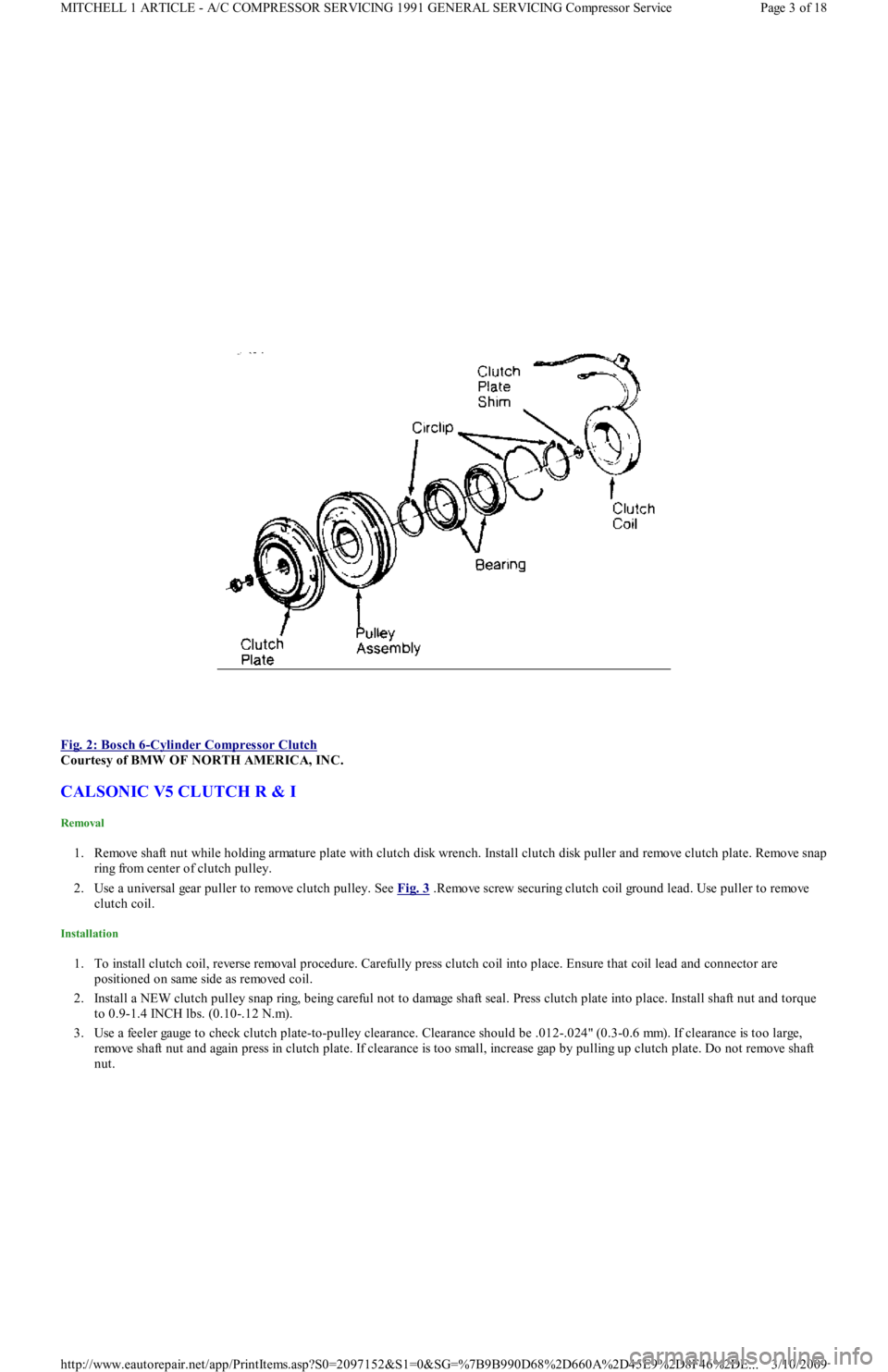
Fig. 2: Bosch 6
-Cylinder Compressor Clutch
Courtesy of BMW OF NORTH AMERICA, INC.
CALSONIC V5 CLUTCH R & I
Removal
1. Remove shaft nut while holding armature plate with clutch disk wrench. Install clutch disk puller and remove clutch plate. Remo ve sn ap
ring from center of clutch pulley.
2. Use a universal gear puller to remove clutch pulley. See Fig. 3
.Remove screw securing clutch coil ground lead. Use puller to remove
clutch coil.
Installation
1. To install clutch coil, reverse removal procedure. Carefully press clutch coil into place. Ensure that coil lead and connector are
positioned on same side as removed coil.
2. Install a NEW clutch pulley snap ring, being careful not to damage shaft seal. Press clutch plate into place. Install shaft nut and torque
to 0.9-1.4 INCH lbs. (0.10-.12 N.m).
3. Use a feeler gauge to check clutch plate-to-pulley clearance. Clearance should be .012-.024" (0.3-0.6 mm). If clearance is too large,
remove shaft nut and again press in clutch plate. If clearance is too small, increase gap by pulling up clutch plate. Do not remo ve sh aft
nut.
Page 3 of 18 MITCHELL 1 ARTICLE - A/C COMPRESSOR SERVICING 1991 GENERAL SERVICING Compressor Service
3/10/2009 http://www.eautorepair.net/app/PrintItems.asp?S0=2097152&S1=0&SG=%7B9B990D68%2D660A%2D45E9%2D8F46%2DE
...