1991 FORD FESTIVA speedometer
[x] Cancel search: speedometerPage 2 of 454
Back To Article
INST RUMENT PANEL
1991 ACCESSORIES & SAFET Y EQUIPMENT Ford Motor Co. Switches & Instrum ent Panels - Standard
DESCRIPTION & OPERATION
Instrument panel on Capri contains a speedometer, tachometer, fuel, water temperature, oil pressure and voltmeter gauges. A boost gauge is
incorporated into the tachometer on turbo models. Instrument panel is equipped with indicator/warning lights for charging system, air b ag,
manual shift, seat belt, turn signals, high beam and brakes. A CHECK ENGINE light, located on instrument panel, illuminates if a
computerized engine control fault occurs with engine running.
Instrument panel on Festiva contains a speedometer, fuel and water temperature gauges. Instrument panel is equipped with indicator/warning
lights for charging system, oil pressure, seat belt, rear defogger, turn signals, high beam and brakes. A CHECK ENGINE light, located on
instrument panel, illuminates if a computerized engine control fault occurs with engine running.
TROUBLE SHOOTING
FUEL GAUGE
Fuel Gauge Always Reads Empty
If fuel gauge always reads empty, check these items:
Check fuel gauge for open or damaged wires.
Check for open ground at fuel gauge sending unit.
Check for defective fuel sending unit.
Check for defective fuel gauge.
Check for defective instrument panel voltage regulator (Festiva).
Check for blown 10-amp METER fuse in fuse panel.
Check for open in Black/Yellow power feed wire from fuse panel instrument panel.
Check for fuel tank float full of fuel (sunk).
Fuel Gauge Always Reads Full
If fuel gauge always reads full, check these items:
Check for fuel gauge Yellow wire shorted to ground.
Check for defective fuel sending unit.
Check for defective fuel gauge.
Check for defective instrument panel voltage regulator (Festiva).
Fuel Gauge Inaccurate
If fuel gauge is inaccurate, check these items:
Check for faulty (loose or corroded) wire connections.
Check for defective fuel sending unit.
Check for defective instrument panel voltage regulator (Festiva).
TEMPERATURE GAUGE
Temperature Gauge Always Reads Cold
If temperature gauge always reads cold, check these items:
Check temperature gauge for open wire.
Check for defective temperature sender.
Check for defective temperature gauge.
Check for defective instrument panel voltage regulator (Festiva).
Check for blown 10-amp METER fuse in fuse panel.
Check for open in Black/Yellow power feed wire from fuse panel to instrument panel.
Temperature Gauge Always Reads Hot
CAUT ION: On m odels with Supplem ental Restraint System (SRS), observe safety precautions. T he air bag system
is powered directly from the battery and back-up power supply. Before any repairs are perform ed,
disconnect and shield battery ground cable. Disconnect the back-up power supply BEFORE servicing
ANY air bag com ponent. Use caution when working near steering colum n. Air bag could accidentally
deploy at any tim e.
NOTE:Ensure continuity exists between chassis ground and Black wire of instrum ent panel connector,
especially if fault exists in m ultiple gauge circuits. See appropriate chassis wiring diagram in the
WIRING DIAGRAMS Section.
Page 1 of 5 MITCHELL 1 ARTICLE - INSTRUMENT PANEL 1991 ACCESSORIES & SAFETY EQUIPMENT Ford Motor Co. Switches
...
3/10/2009 http://www.eautorepair.net/app/PrintItems.asp?S0=2097152&S1=0&SG=%7B959286D2%2D3A85%2D4BFC%2D9C5C%2D
...
Page 3 of 454
If temperature gauge always reads hot, check these items:
Check for temperature gauge wire shorted to ground.
Check for defective temperature sender.
Check for defective temperature gauge.
Check for defective instrument panel voltage regulator (Festiva).
Temperature Gauge Inaccurate
If temperature gauge is inaccurate, check these items:
Check for faulty (loose or corroded) wire connections.
Check for defective temperature sender.
Check for defective instrument panel voltage regulator (Festiva).
SPEEDOMETER
Speedometer Does Not Operate
If speedometer does not operate, check these items:
Check for broken speedometer drive cable.
Check for broken drive gear in transmission.
Check for defective speedometer head.
Speedometer Needle Bounces
If speedometer needle bounces, check these items:
Check for binding speedometer drive cable.
Check for missing teeth on drive gear in transmission.
Check for defective speedometer head.
Speedometer Does Not Indicate Correct Vehicle Speed
If speedometer does not indicate correct vehicle speed, check these items:
Check for incorrect size tires.
Check for improper tire inflation.
Check for defective speedometer head.
TACHOMETER (CAPRI)
Tachometer Does Not Work, But All Other Gauges Work Properly
-If tachometer does not work, but all other gauges function properly, check these items:
Check for defective tachometer.
Check for open Yellow/Black tachometer signal wire from ignition coil to instrument panel.
Check for faulty Black ground wire to instrument panel.
Tachometer & All Gauges Do Not Function
If tachometer and all other gauges do not function properly, check these items:
Check for blown 10-amp METER fuse in fuse panel.
Check for open in Black/Yellow wire to fuse panel to instrument panel and Black/White wire from ignition switch to fuse panel
Tachometer Reading Low
If tachometer reading is lower than normal, check these items:
Check for defective tachometer.
Check for faulty Black ground wire at instrument panel.
TURBO BOOST GAUGE (CAPRI)
Turbo Boost Gauge Always Reads Low
If turbo boost gauge always reads low, check these items:
Check boost gauge for open or damaged wires.
Check for defective boost sensing unit.
Check for defective boost gauge.
Check for blown 10-amp METER fuse in fuse panel.
Check for loose or corroded connections.
Page 2 of 5 MITCHELL 1 ARTICLE - INSTRUMENT PANEL 1991 ACCESSORIES & SAFETY EQUIPMENT Ford Motor Co. Switches
...
3/10/2009 http://www.eautorepair.net/app/PrintItems.asp?S0=2097152&S1=0&SG=%7B959286D2%2D3A85%2D4BFC%2D9C5C%2D
...
Page 5 of 454

TURBO BOOST GAUGE & SENSOR (CAPRI)
1. Disconnect 3-pin boost sensor electrical connected located on right side of firewall. Turn ignition on. Measure voltage between
Yellow/Green and Black wires. Voltage should be greater than 10 volts. Turn ignition off. If voltage is greater than 10 volts, go t o n e xt
step. If voltage is 10 volts or less, repair Yellow/Green or Black wires as necessary.
2. Remove instrument panel. See INSTRUMENT PANEL
under REMOVAL & INSTALLATION. Disconnect instrument panel 8-pin
connector. With boost sensor disconnected, measure resistance through White/Black between instrument panel and boost sensor harness
connector. If resistance is less than 5 ohms, go to next step. If resistance is 5 ohms or more, repair or replace White/Black wire.
3. With 8-pin instrument panel connector disconnected, ground White/Black at boost gauge. Boost gauge should read low. Apply 12 vo l t s
to White/Black wire at boost gauge. Boost gauge should read high. If boost gauge operates as specified, go to next step. If boost gauge
does not operate as specified, replace boost gauge.
4. Reconnect instrument panel connectors (if removed). With ignition on and boost sensor disconnected, install jumper wire between
Yellow/Green and White/Black wires of boost sensor vehicle harness connector. Boost gauge should read high. If boost gauge reads
high, replace boost sensor. If boost gauge does not read high, go to TROUBLE SHOOTING
for other possible causes.
REMOVAL & INSTALLATION
INSTRUMENT PANEL
Removal & Installation (Capri)
1. Disconnect negative battery cable. Pull storage compartment from heater/radio bezel. Pull outward and remove trim covers located on
both sides of steering column. Remove retaining screws and carefully pull instrument panel bezel partially away from dash. Disconnect
electrical connectors from clock and switches in bezel. Remove instrument panel bezel.
2. Disconnect speedometer cable from transaxle. Remove instrument panel retaining screws and slide instrument panel outward. Press lock
tab and release speedometer cable from instrument panel. Remove electrical connectors from rear of instrument panel. Remove
instrument panel. To install instrument panel, reverse removal procedure.
Removal & Installation (Festiva)
1. Disconnect negative battery cable. Remove upper and lower steering column covers. Remove screws from panel bezel and remove bezel.
Disconnect rear wiper switch and rear defogger switch wiring harness connectors (if equipped).
2. Remove instrument panel-to-dash screws. Pull panel from dash. Reach behind panel and release speedometer drive cable lock tab. Lift
lock tabs and disconnect 2 electrical connectors from rear of panel. Remove panel. To install instrument panel, reverse removal
procedure.
INDICATOR LIGHTS
Removal & Installation
Remove instrument panel for access to indicator light bulbs. See INSTRUMENT PANEL under REMOVAL & INSTALLATION. To remove
bulb, rotate bulb counterclockwise to disengage locking tabs. When tabs release, pull bulb from printed circuit board. To install bulb, reverse
removal procedure. Install instrument panel and test lights.
SPEEDOMETER R & I
Removal & Installation (Capri)
R e mo ve n e ga t ive b a t t e r y c a b l e . R e mo ve in st r u me n t p a n e l . S e e INSTRUMENT PANEL under REMOVAL & INSTALLATION. Disassemble
instrument panel and remove speedometer/tachometer/boost gauge assembly from instrument panel. To install, apply a 3/16" (4.6 mm) b al l o f
Silicone Damping Grease (D7AZ-19A331-A) into drive hole of speedometer head. Reverse removal procedure to complete installation.
Removal & Installation (Festiva)
R e mo ve n e ga t ive b a t t e r y c a b l e . R e mo ve in st r u me n t p a n e l . S e e INSTRUMENT PANEL under REMOVAL & INSTALLATION. Disassemble
instrument panel and remove speedometer head assembly from instrument panel. Speedometer is a separate module and can be removed
independently from gauges. To install, reverse removal procedure.
SPEED SENSOR
On vehicles equipped with speed control, a speed sensor is mounted in speedometer head assembly. If replacement is necessary, speedometer
head assembly must be replaced. See SPEEDOMETER R & I
under REMOVAL & INSTALLATION.
FUEL GAUGE
Removal & Installation
Remo ve in st ru men t p an el . See INSTRUMENT PANEL under REMOVAL & INSTALLATION. Disassemble panel and remove fuel gauge.
To install gauge, reverse removal procedure. On Capri, the fuel/volt gauge must be replaced as an assembly.
FUEL SENDING UNIT
Removal & Installation
1. For Festiva, remove rear seat. For Capri, remove rear seat cushion. On Festiva, remove carpet hold-down pins and lift carpet for access
to sending unit access plate. On all models, remove access plate screws. NOTE:Federal law requires that a label stating the odom eter has been repaired or replaced be affixed to any
vehicle that has its odom eter repaired, replaced or set to zero.
Page 4 of 5 MITCHELL 1 ARTICLE - INSTRUMENT PANEL 1991 ACCESSORIES & SAFETY EQUIPMENT Ford Motor Co. Switches
...
3/10/2009 http://www.eautorepair.net/app/PrintItems.asp?S0=2097152&S1=0&SG=%7B959286D2%2D3A85%2D4BFC%2D9C5C%2D
...
Page 6 of 454
2. Lift access plate and disconnect sending unit wiring. To relieve fuel pressure, start engine and run it until engine stalls. Turn ignition off.
Disconnect and plug fuel lines at sending unit. Remove sending u n it a t t a c h in g sc r e ws. R e mo ve se n d in g u n it . To in st a l l , r e ve r se removal
procedure.
TACHOMETER
Removal & Installation
Remo ve in st ru men t p an el . See INSTRUMENT PANEL under REMOVAL & INSTALLATION. Disassemble panel and remove tachometer.
To install tachometer, reverse removal procedure. On Capri, the tachometer/speedometer/boost gauge assembly must be replaced as an
assembly.
TEMPERATURE GAUGE
Removal & Installation
Remo ve in st ru men t p an el . See INSTRUMENT PANEL under REMOVAL & INSTALLATION. Disassemble panel and remove temperature
gauge. To install gauge, reverse removal procedure. On Capri, the temperature/oil pressure gauge assembly must be replaced as an assembly.
TEMPERATURE SENDING UNIT
Removal
Disconnect sending unit wire, located on side of block below thermostat housing (Festiva) or cylinder head (Capri). Remove radiator cap to
relieve cooling system pressure. Position drain pan below sending unit. Remove temperature sending unit.
Installation
To install, apply Pipe Sealant With Teflon (D8AZ-19554-A) to threads of sending unit. Reverse removal procedure to complete installation.
Fill cooling system to proper level. Start engine and check for coolant leaks at sending unit.
WIRING DIAGRAMS
CAUT ION: T achom eter is calibrated at factory. Rough handling could disturb calibration.
NOTE:Refer to the appropriate WIRING DIAGRAMS article in the WIRING DIAGRAMS section.
Copyr ight 2009 Mitchell Repair Information Company, LLC. All Rights Reserved.
Article GUID: A00028301
Page 5 of 5 MITCHELL 1 ARTICLE - INSTRUMENT PANEL 1991 ACCESSORIES & SAFETY EQUIPMENT Ford Motor Co. Switches
...
3/10/2009 http://www.eautorepair.net/app/PrintItems.asp?S0=2097152&S1=0&SG=%7B959286D2%2D3A85%2D4BFC%2D9C5C%2D
...
Page 101 of 454
Back To Article
ENGINE OVERHAUL
1991-92 FORD MOT OR CO. ENGINES 1.3L & 1.6L 4-Cylinder
ENGINE IDENTIFICATION
Engine can be identified by Vehicle Identification Number (VIN) on metal tab attached to instrument panel. Tab is close to windshield on
driver's side and is visible through windshield. VIN has 17 characters. The 8th character identifies engine.
ENGINE IDENTIFICATION CODES
ADJUSTMENTS
VALVE ARRANGEMENT
Firewall Side
In t ake val ves.
Radiator Side
Exhaust valves.
VALVE CLEARANCE ADJUSTMENT
Hydraulic lifters are used. Adjustment is NOT possible nor necessary.
REMOVAL & INSTALLATION
FUEL PRESSURE RELEASE
Remove rear seat. Remove fuel pump access panel. Disconnect fuel pump electrical connector. Start engine and allow to idle until engine dies.
ENGINE
Removal (1.3L)
1. Remove battery and battery tray. Index hood-to-hinge and remove hood. Drain coolant. Drain engine oil and transaxle fluid. Disconnect
vane airflow meter connector, vane airflow meter and hose.
2. Remove oil dipstick, cooling fan and radiator assembly. Disconnect accelerator cable from mounting bracket and throttle lever.
Disconnect speedometer cable at transaxle. Mark and disconnect fuel lines at fuel pump. Plug fuel lines. Remove heater hoses. Remove
brake booster vacuum hose. Disconnect transaxle vacuum hose.
3. Remove charcoal canister hoses from engine. Disconnect engine wiring harness. Remove alternator and brackets. Remove engine ground
strap. Raise vehicle and remove catalytic converter.
4. Disconnect A/C compressor without removing hoses, and set compressor aside. Disconnect distributor wiring at coil. On automatic
transaxle models, remove shift lever-to-manual shaft assembly nut. Remove shift cable from transaxle. Loosen front wheel bolts. Raise
vehicle and remove wheel assemblies.
5. Remove stabilizer mounting nuts and brackets. Remove lower arm clamp bolts and nuts. Pull lower arms downward, separating lower
arms from knuckles. Separate halfshafts and install Differential Plugs (T87C-7025-C) between differential side gears. See FWD AXLE
SHAFTS article in DRIVE AXLES Section.
6. On manual transaxle vehicles, disconnect clutch control cable and shift control cable rod. Remove stabilizer bar from transaxle. Remove
catalytic converter inlet pipe. Support engine assembly with hoist. Remove rear crossmember mount bolts. Remove front and rear engine
mount nuts.
7. Remove crossmember. Lower vehicle and attach engine lift hooks. Remove right engine mount bolt. Remove engine/transaxle assembly.
Remove gusset plates. Remove starter and flywheel cover. Remove torque converter bolts on automatic transaxle. Remove engine-to-
transaxle bolts. Separate transaxle from engine.
Installation (1.3L)
1. Install transaxle to engine in reverse order of removal. Attach hoist to engine/transaxle assembly and position in vehicle. Support engine
in chassis and install engine mount bolts. Raise vehicle and install front engine mount nut. Tighten nuts to specification. See TORQUE
SPECIFICATIONS table at end of article.
2. Position crossmember onto mounts and chassis. Tighten rear nut. Install mount-to-crossmember nuts and tighten. Remove differential
plugs and install halfshafts. To complete installation, reverse removal procedure. Tighten all bolts/nuts to specifications. Fill all fluid NOTE:For engine repair procedures not covered in this article, see ENGINE OVERHAUL PROCEDURES
-
GENERAL INFORMATION
article in the GENERAL INFORMAT ION section.
ApplicationVIN Code
Festiva
1.3L SOHC PFIH
Capri
1.6L DOHC PFIZ
1.6L DOHC PFI TURBO6
NOTE:When rem oving engine m ounts, m ark and note location and position to ensure proper installation.
Engine and transaxle are rem oved as an assem bly.
Page 1 of 19 MITCHELL 1 ARTICLE - ENGINE OVERHAUL 1991-92 FORD MOTOR CO. ENGINES 1.3L & 1.6L 4-Cylinder
3/10/2009 http://www.eautorepair.net/app/PrintItems.asp?S0=2097152&S1=0&SG=%7B959286D2%2D3A85%2D4BFC%2D9C5C%2D
...
Page 102 of 454

levels to proper level.
Removal (1.6L & 1.6L Turbo)
1. Relieve fuel pressure and discharge air conditioning system (if equipped). See FUEL PRESSURE RELEASE under REMOVAL &
INSTALLATION. Disconnect and remove battery, battery tray and battery tray support bracket.
2. Release wiring harness retaining straps from battery support tray. Disconnect windshield washer supply hose between fluid reservoir and
hood. Mark hinge locations and remove hood.
3. Disconnect intake air tube and wiring to ignition coil and vane airflow meter. Remove air cleaner/vane airflow meter assembly. Remove
air cleaner assembly support brackets. Disconnect intercooler hoses from turbocharger (if equipped).
4. Drain engine coolant and remove radiator. Disconnect accelerator cable, and remove retaining bracket from cam cover. Position cable to
one side.
5. Disconnect and plug fuel lines at fuel filter and pressure regulator. Disconnect power brake booster manifold vacuum hose from
manifold. Disconnect heater hoses at heater core tubes. Label and remove vacuum hoses located at throttle body.
6. For manual transaxle turbocharged vehicles, disconnect clutch cable and remove support bracket and cable from transmission. On non-
turbo vehicles, disconnect clutch slave hydraulic line. For automatic transaxle, remove transaxle cooler lines.
7. Disconnect starter wiring at starter. Remove harness from locating strap on bracket. Disconnect alternator wiring. Disconnect wiring
from engine coolant sensors located on rear of engine block. Remove ground connection at bracket on thermostat cover. Disconnect O2
sensor wire, main wiring harness connector, TPS connector (turbocharged only), knock sensor connector, distributor wiring and
transaxle wiring. Disconnect ground wire and strap at front of engine, and reinstall lifting eye.
8. Remove engine oil dipstick and retaining clip. Remove power steering pump from mounting bracket. Remove power steering pump
mounting bracket. With hoses attached, position pump aside. Remove upper air conditioning compressor retaining bolts (if equipped).
9. Raise vehicle on hoist. Drain engine oil and cooling system. On vehicles with air conditioning, remove lower air conditioning
compressor mounting bolts, and position compressor out of way.
10. Remove front wheels and tires. Remove front ball joints-to-ste e r in g kn u c kl e s r e t a in in g b o l t s. R e mo ve sp l a sh gu a r d s. Dr a in t ransmission
oil and remove half shafts from differential. Remove front exhaust pipe bracket located on lower side of engine. Disconnect front
exhaust pipe from exhaust manifold, or turbocharger (if equipped).
11. Remove frame support bar-to-engine support bolt. Loosen right control arm bolt and, pivot support bar downward. Disengage rubber
exhaust hangers located directly behind catalytic converter. Allow exhaust system to hang down 6 inches, and support system with
mechanic's wire. Unbolt shift linkage and stabilizer bar at transaxle. Remove nuts from front and rear engine mounts, and lower vehicle.
12. Attach chains onto lift eyes at ends of cylinder head, and support engine with hoist. Remove RH engine mount through bolt. Raise
engine off mounts and slightly pivot engine/transaxle assembly. Disconnect oil pressure sensor and route starter/alternator wiring
harness from engine. Carefully lift engine/transaxle assembly, turn assembly while raising to clear brake master cylinder, shift linkage
universal joint, radiator support and air conditioning lines (if equipped).
13. Remove intake manifold support bracket. Remove gusset plate(s) (if equipped). Remove starter. Remove transaxle-to-engine retaining
bolts. Identify bolts to ensure correct installation. Separate transaxle from engine. On manual transaxle, remove pressure plate, clutch
disc and flywheel. On automatic transaxle, remove flexplate.
Installation (1.6L & 1.6L Turbo)
1. Install transaxle to engine in reverse order of removal. Attach hoist to engine/transaxle assembly and position assembly in vehicle.
Before engine contacts mounts, route starter, alternator and oil pressure sensor wiring, and connect oil pressure sensor. Lower engine
until front mount seats on crossmember. Install through bolt on RH engine mount. DO NOT tighten bolt.
2. Remove hoist. Raise vehicle and support with jackstands. Align rear engine mount to crossmember, and install retaining nuts to front
and rear engine mounts. Tighten nuts to specification. See TORQUE SPECIFICATIONS
table at end of article.
3. On manual transaxles, connect shift coupling and stabilizer. Tighten to specification. On automatic transaxles, connect shift linkage and
oil cooler lines. Tighten linkage retaining bolt, shift cable pivot and oil cooler hose clamps to specification. Connect front exhaust pipe
to manifold (or turbocharger). Install exhaust pipe to support bracket. Tighten bolts to specification. Tighten manifold (or turbocharger)
to specification. Attach rubber exhaust hangers. Position cross brace. Tighten retaining nut and bolt and right control arm front bolt.
4. Install drive axles. Install ball joint retaining bolts and tighten to specification. Mount A/C Compressor to engine (if equipped). Tighten
lower retaining bolts to specification. Install splash guards. Install tire and wheel assemblies. Tighten retaining nuts to specification.
5. Lower vehicle. Install upper A/C compressor retaining bolts (if equipped). Tighten bolts to specification. Tighten RH engine mo u n t
through bolt to specification. Connect alternator wiring.
6. Position power steering pump bracket on stud. Lower pump into engine compartment. Install power steering pump bracket retaining
bolts and nut. Tighten to specification. Install power steering pump and belt. Tighten adjustment nut and pivot bolt to specification.
7. Install engine oil dipstick and retaining clip. Install ground strap and ground wire to cylinder head. Install clutch cable (if equipped).
Connect clutch hydraulic line if equipped with manual transaxle or naturally aspirated. Connect transmission electrical connectors.
Connect fuel lines to fuel filter and pressure regulator. Install intake air tube to throttle body.
8. Install intercooler hoses on turbocharged models. Install air cleaner assembly brackets. Install air cleaner assembly with airflow meter
attached. Install intake air tube. Install coil and airflow meter connectors. Connect coolant crankcase and air bypass hoses. Install
vacuum hoses as noted in disassembly.
9. Connect accelerator cable. Install retaining bracket. Install power brake booster hose. Remove speedometer cable from transaxle. Fill
transaxle to specification. See CAPACITIES in SERVICE & ADJUSTMENT SPECIFICATIONS article. Install speedometer cable.
Connect speedometer cable connector. Fill engine oil to capacity.
10. Install radiator/fan assembly. Tighten bracket retaining bolts to specification. Connect coolant hoses and fan electrical connector. Fill
coolant to specification.
11. Install hood and connect washer hose. Install battery tray support, battery tray, battery and battery hold-down. Connect battery
terminal. Evacuate and charge air conditioning system (if equipped). Road test vehicle and inspect for leaks.
INTAKE MANIFOLD
Removal (1.3L)
CAUT ION: DO NOT allow com pressor to hang by hoses. T ie up com pressor with m echanic's wire.
Page 2 of 19 MITCHELL 1 ARTICLE - ENGINE OVERHAUL 1991-92 FORD MOTOR CO. ENGINES 1.3L & 1.6L 4-Cylinder
3/10/2009 http://www.eautorepair.net/app/PrintItems.asp?S0=2097152&S1=0&SG=%7B959286D2%2D3A85%2D4BFC%2D9C5C%2D
...
Page 175 of 454
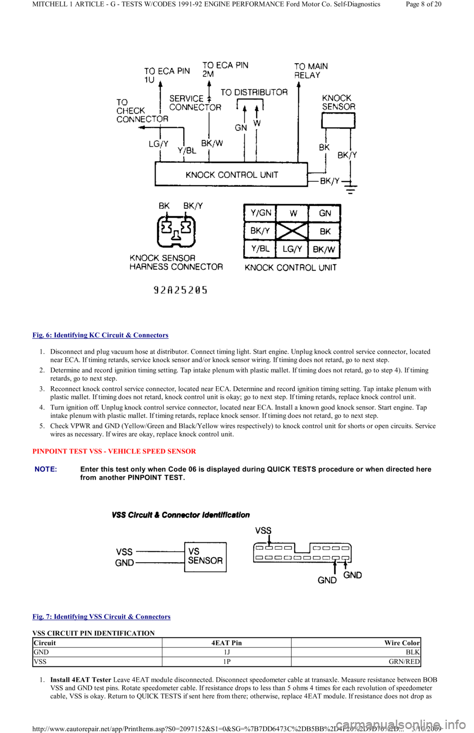
Fig. 6: Identifying KC Circuit & Connectors
1. Disconnect and plug vacuum hose at distributor. Connect timing light. Start engine. Unplug knock control service connector, located
near ECA. If timing retards, service knock sensor and/or knock sensor wiring. If timing does not retard, go to next step.
2. Determine and record ignition timing setting. Tap intake plenum with plastic mallet. If timing does not retard, go to step 4). If t imin g
retards, go to next step.
3. Reconnect knock control service connector, located near ECA. Determine and record ignition timing setting. Tap intake plenum with
plastic mallet. If timing does not retard, knock control unit is okay; go to next step. If timing retards, replace knock control unit.
4. Turn ignition off. Unplug knock control service connector, located near ECA. Install a known good knock sensor. Start engine. Tap
intake plenum with plastic mallet. If timing retards, replace knock sensor. If timing does not retard, go to next step.
5. Check VPWR and GND (Yellow/Green and Black/Yellow wires respectively) to knock control unit for shorts or open circuits. Service
wires as necessary. If wires are okay, replace knock control unit.
PINPOINT TEST VSS - VEHICLE SPEED SENSOR
Fig. 7: Identifying VSS Circuit & Connectors
VSS CIRCUIT PIN IDENTIFICATION
1.Install 4EAT Tester Leave 4EAT module disconnected. Disconnect speedometer cable at transaxle. Measure resistance between BOB
VSS and GND test pins. Rotate speedometer cable. If resistance drops to less than 5 ohms 4 times for each revolution of speedometer
cable, VSS is okay. Return to QUICK TESTS if sent here from there; otherwise, replace 4EAT module. If resistance does not drop as
NOTE:Enter this test only when Code 06 is displayed during QUICK T EST S procedure or when directed here
from another PINPOINT TEST.
Circuit4EAT PinWire Color
GND1JBLK
VSS1PGRN/RED
Page 8 of 20 MITCHELL 1 ARTICLE - G - TESTS W/CODES 1991-92 ENGINE PERFORMANCE Ford Motor Co. Self-Diagnostics
3/10/2009 http://www.eautorepair.net/app/PrintItems.asp?S0=2097152&S1=0&SG=%7B7DD6473C%2DB5BB%2D4F20%2D9D70%2D
...
Page 176 of 454
specified, go to next step.
2. Unplug VSS connector at instrument cluster. Measure resistance between VSS and GND terminals on instrument cluster. Rotate
speedometer cable. If resistance drops to less than 5 ohms 4 times for each revolution of speedometer cable, repair VSS signal wire to
4EAT. If resistance does not drop as specified, replace speedometer assembly.
PINPOINT TEST VAF - VANE AIRFLOW METER
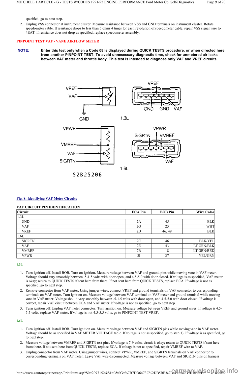
Fig. 8: Identifying VAF Meter Circuits
VAF CIRCUIT PIN IDENTIFICATION
1.3L
1. Turn ignition off. Install BOB. Turn on ignition. Measure voltage between VAF and ground pins while moving vane in VAF meter.
Voltage should vary smoothly between .5-1.5 volts with door open, and 4.5-5.0 with door closed. If voltage is as specified, VAF met er
is okay; return to QUICK TESTS if sent here from there. If not sent here from QUICK TESTS, replace ECA. If voltage is not as
specified, go to next step.
2. Remove connector from VAF meter. Using jumper wires, connect VREF and ground terminals on VAF connector to corresponding
terminals on VAF meter. Turn ignition on. Measure voltage between VAF terminal on VAF meter and ground terminal while moving
vane in VAF meter. Voltage should vary smoothly between .5-1.5 volts with door open, and 4.5-5.0 with door closed. If voltage is
correct, repair VAF circuit between ECA and VAF meter. If voltage is not as specified, go to next step.
3. Turn ignition off. Unplug VAF meter connector. Turn ignition on. Measure voltage between VREF and ground wires. If voltage is 4.5-
5.5 volts, replace VAF meter. If voltage is not 4.5-5.5 volts, go to PINPOINT TEST VREF.
1.6L
1. Turn ignition off. Install BOB. Turn ignition on. Measure voltage between VAF and SIGRTN pins while moving vane in VAF meter.
Voltage should be as specified in VAF METER VOLTAGE table. If voltage is not as specified, go to step 3). If voltage is as specified, go
to next step.
2. Measure voltage between VMREF and SIGRTN test pins. If voltage is 7-9 volts, circuit is okay; return to QUICK TESTS if sent here
from there. If not sent here from QUICK TESTS, replace ECA. If voltage is not as specified, repair VMREF wire to VAF.
3. Unplug connector from VAF meter. Using jumper wires, connect VPWR, VMREF, and SIGRTN terminals on VAF connector to
corresponding terminals on VAF meter. Leave VAF wire disconnected. Measure voltage between VAF and SIGRTN pins on harness NOTE:Enter this test only when a Code 08 is displayed during QUICK TESTS procedure, or when directed here
from another PINPOINT T EST . T o avoid unnecessary diagnostic tim e, check for unm etered air leaks
between VAF m eter and throttle body. T his test is intended to diagnose only VAF and VREF circuits.
CircuitECA PinBOB PinWire Color
1.3L
GND2A45BLK
VAF2O25WHT
VREF2D46, 49BLK
1.6L
SIGRTN2C46BLK/YEL
VAF2E43LT GRN/BLK
VMREF2B18LT GRN/RED
VPWR3I37YEL/GRN
Page 9 of 20 MITCHELL 1 ARTICLE - G - TESTS W/CODES 1991-92 ENGINE PERFORMANCE Ford Motor Co. Self-Diagnostics
3/10/2009 http://www.eautorepair.net/app/PrintItems.asp?S0=2097152&S1=0&SG=%7B7DD6473C%2DB5BB%2D4F20%2D9D70%2D
...