1991 FORD FESTIVA oil type
[x] Cancel search: oil typePage 114 of 454
2. Remove main bearing cap bolts. Remove cap and lower bearing insert. Use bearing remover or fabricated cotter key to remove upper
bearing insert. Insert bearing remover in journal lubrication hole. Rotate crankshaft in normal direction of operation only. Repeat
procedure for remaining main bearings.
3. Check bearings for abnormal wear. Check crankshaft for grooves, scratches and pitting. Using Plastigage method, check clearance of
main bearing-to-crankshaft. Always keep at least 2 bearings and caps tight during clearance check. See, at end of article,
CRANKSHAFT MAIN & CONNECTING ROD BEARINGS
table under ENGINE SPECIFICATIONS.
4. Lubricate and install new bearings in cap and block. Match bearing tangs with notch in cap and block. Position cap in its proper
location and position. Install cap bolts and tighten to specification. See TORQUE SPECIFICATIONS
table at end of article. Repeat
procedure for remaining main bearings.
CRANKSHAFT END PLAY
Check crankshaft end play with dial indicator. End play should be .0031-.0111" (.08-.282 mm). Service limit is .012" (.30 mm). If end play is
not within specification, replace thrust bearings as necessary.
CYLINDER BLOCK
1. Using straightedge and feeler gauge, check entire cylinder head surface of cylinder block. Ensure warpage does not exceed .006" (.15
mm). If warpage exceeds specification, cylinder block surface can be machined a maximum of .008" (.20 mm).
2. Replace cylinder block if it needs to be machined more than .008" (.20 mm). Check cylinder bore for wear, out-of-round, taper and
piston fit. See CYLINDER BORE SPECIFICATIONS
table. Oversize pistons are available in .010" and .020" (.25 mm and .50 mm).
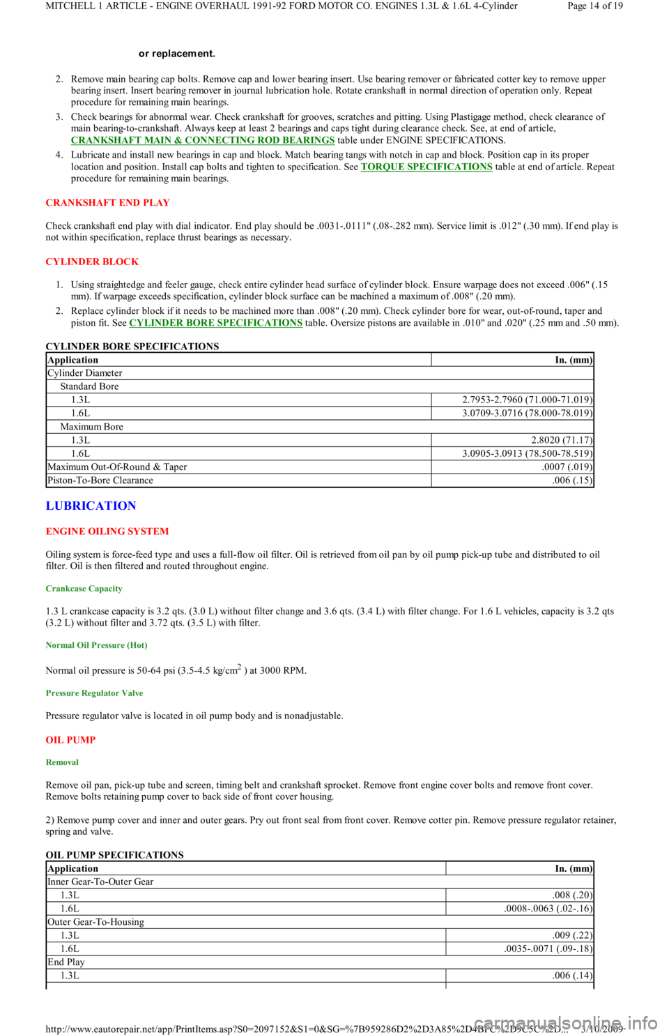
CYLINDER BORE SPECIFICATIONS
LUBRICATION
ENGINE OILING SYSTEM
Oiling system is force-feed type and uses a full-flow oil filter. Oil is retrieved from oil pan by oil pump pick-up tube and distributed to oil
filter. Oil is then filtered and routed throughout engine.
Crankcase Capacity
1.3 L crankcase capacity is 3.2 qts. (3.0 L) without filter change and 3.6 qts. (3.4 L) with filter change. For 1.6 L vehicles, capacity is 3.2 qts
(3.2 L) without filter and 3.72 qts. (3.5 L) with filter.
Normal Oil Pressure (Hot)
Normal oil pressure is 50-64 psi (3.5-4.5 kg/cm2 ) at 3000 RPM.
Pressure Regulator Valve
Pressure regulator valve is located in oil pump body and is nonadjustable.
OIL PUMP
Removal
Remove oil pan, pick-up tube and screen, timing belt and crankshaft sprocket. Remove front engine cover bolts and remove front cover.
R e mo ve b o l t s r e t a in in g p u mp c o ve r t o b a c k sid e o f fr o n t c o ve r h o u sin g.
2) Remove pump cover and inner and outer gears. Pry out front seal from front cover. Remove cotter pin. Remove pressure regulator retainer,
spring and valve.
OIL PUMP SPECIFICATIONS or replacem ent.
ApplicationIn. (mm)
Cylinder Diameter
Standard Bore
1.3L2.7953-2.7960 (71.000-71.019)
1.6L3.0709-3.0716 (78.000-78.019)
Maximu m Bo re
1.3L2.8020 (71.17)
1.6L3.0905-3.0913 (78.500-78.519)
Maximu m Ou t -Of-Ro u n d & Tap er.0007 (.019)
Piston-To-Bore Clearance.006 (.15)
ApplicationIn. (mm)
Inner Gear-To-Outer Gear
1.3L.008 (.20)
1.6L.0008-.0063 (.02-.16)
Outer Gear-To-Housing
1.3L.009 (.22)
1.6L.0035-.0071 (.09-.18)
End Play
1.3L.006 (.14)
Page 14 of 19 MITCHELL 1 ARTICLE - ENGINE OVERHAUL 1991-92 FORD MOTOR CO. ENGINES 1.3L & 1.6L 4-Cylinder
3/10/2009 http://www.eautorepair.net/app/PrintItems.asp?S0=2097152&S1=0&SG=%7B959286D2%2D3A85%2D4BFC%2D9C5C%2D
...
Page 154 of 454

VALVE CLEARANCE
IGNITION SYSTEM
IGNITION COIL
IGNITION COIL RESISTANCE
CRANKSHAFT POSITION SENSOR
CRANKSHAFT POSITION SENSOR RESISTANCE
HIGH TENSION WIRE RESISTANCE
HIGH TENSION WIRE RESISTANCE
SPARK PLUGS
SPARK PLUG TYPE
SPARK PLUG SPECIFICATIONS
FIRING ORDER & TIMING MARKS
Fig. 1: Firing Order & Distributor Rotation
IGNITION TIMING
(1)Information is not available.
(2)Lowest cylinder compression reading should not be less than 75 percent of highest cylinder compression reading.
NOTE:All m odels are equipped with hydraulic lash adjusters. No adjustm ents are required.
ApplicationPrimary (Ohms)Secondary (Ohms)
1.3L & 1.6L0.8-1.66000-30,000
ApplicationOhms
1.3L(1) 210-250
1.6L(2)
(1)Measured between CPS (Yellow/Blue) and GND terminal.
(2)Capri is equipped with Cylinder Identification (CID) sensor. Resistance is not specified.
ApplicationOhms
Coil Wire & Spark Plug Wires4000-6000 per foot
ApplicationMotorcraft
1.3LAGS32C
1.6L
Non-TurboAGSP32C
TurboAGS32C
ApplicationGap: In.- (mm)Torque: Ft.-Lbs./(N.m)
1.3L & 1.6L.039-.043 (1.0-1.1)10-17 (14-23)
ApplicationAuto. Trans.Man. Trans.
1.3L9-11 @ 8509-11 @ 700
1.6L Non-Turbo1-3 @ 8500-4 @ 850
1.6L Turbo10-14 @ 8500-4 @ 850
Page 2 of 3 MITCHELL 1 ARTICLE - C - SPECIFICATIONS 1991 ENGINE PERFORMANCE Ford/Mercury - Service & Adjustment Spe
...
3/10/2009 http://www.eautorepair.net/app/PrintItems.asp?S0=2097152&S1=0&SG=%7B7DD6473C%2DB5BB%2D4F20%2D9D70%2D
...
Page 234 of 454
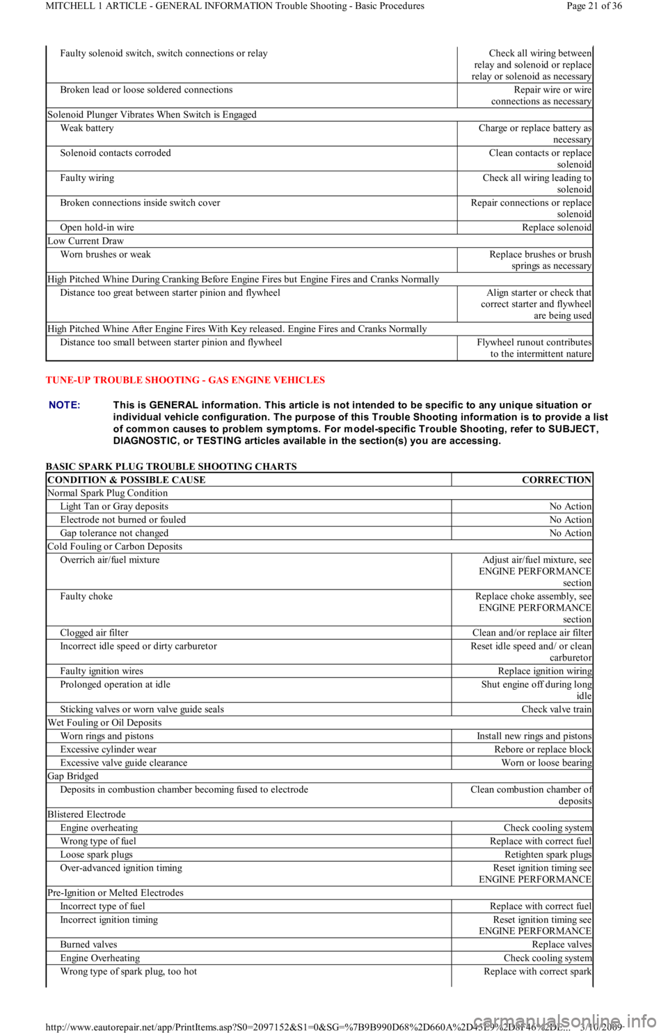
TUNE-UP TROUBLE SHOOTING - GAS ENGINE VEHICLES
BASIC SPARK PLUG TROUBLE SHOOTING CHARTS
Faulty solenoid switch, switch connections or relayCheck all wiring between
relay and solenoid or replace
relay or solenoid as necessary
Broken lead or loose soldered connectionsRepair wire or wire
connections as necessary
Solenoid Plunger Vibrates When Switch is Engaged
Weak batteryCharge or replace battery as
necessary
Solenoid contacts corrodedClean contacts or replace
solenoid
Faulty wiringCheck all wiring leading to
solenoid
Broken connections inside switch coverRepair connections or replace
solenoid
Open hold-in wireReplace solenoid
Low Current Draw
Worn brushes or weakReplace brushes or brush
springs as necessary
High Pitched Whine During Cranking Before Engine Fires but Engine Fires and Cranks Normally
Distance too great between starter pinion and flywheelAlign starter or check that
correct starter and flywheel
are being used
High Pitched Whine After Engine Fires With Key released. Engine Fires and Cranks Normally
Distance too small between starter pinion and flywheelFlywheel runout contributes
to the intermittent nature
NOTE:This is GENERAL inform ation. This article is not intended to be specific to any unique situation or
individual vehicle configuration. T he purpose of this T rouble Shooting inform ation is to provide a list
of com m on causes to problem sym ptom s. For m odel-specific T rouble Shooting, refer to SUBJECT ,
DIAGNOST IC, or T EST ING articles available in the section(s) you are accessing.
CONDITION & POSSIBLE CAUSECORRECTION
Normal Spark Plug Condition
Light Tan or Gray depositsNo Action
Electrode not burned or fouledNo Action
Gap tolerance not changedNo Action
Cold Fouling or Carbon Deposits
Overrich air/fuel mixtureAdjust air/fuel mixture, see
ENGINE PERFORMANCE
section
Faulty chokeReplace choke assembly, see
ENGINE PERFORMANCE
section
Clogged air filterClean and/or replace air filter
Incorrect idle speed or dirty carburetorReset idle speed and/ or clean
carburetor
Faulty ignition wiresReplace ignition wiring
Prolonged operation at idleShut engine off during long
idle
Sticking valves or worn valve guide sealsCheck valve train
Wet Fouling or Oil Deposits
Worn rings and pistonsInstall new rings and pistons
Excessive cylinder wearRebore or replace block
Excessive valve guide clearanceWorn or loose bearing
Gap Bridged
Deposits in combustion chamber becoming fused to electrodeClean combustion chamber of
deposits
Blistered Electrode
Engine overheatingCheck cooling system
Wrong type of fuelReplace with correct fuel
Loose spark plugsRetighten spark plugs
Over-advanced ignition timingReset ignition timing see
ENGINE PERFORMANCE
Pre-Ignition or Melted Electrodes
Incorrect type of fuelReplace with correct fuel
Incorrect ignition timingReset ignition timing see
ENGINE PERFORMANCE
Burned valvesReplace valves
Engine OverheatingCheck cooling system
Wrong type of spark plug, too hotReplace with correct spark
Page 21 of 36 MITCHELL 1 ARTICLE - GENERAL INFORMATION Trouble Shooting - Basic Procedures
3/10/2009 http://www.eautorepair.net/app/PrintItems.asp?S0=2097152&S1=0&SG=%7B9B990D68%2D660A%2D45E9%2D8F46%2DE
...
Page 283 of 454

Circuits with external injector resistors. Used predominately on some Asian & European systems, they are used to reduce the available
voltage to an injector in order to limit the current flow. This lower voltage can cause a dim flash on a noid light designed for full voltage.
Circuits with current controlled injector drivers (e.g. "Peak and Hold"). Basically, this type of driver allows a quick burst of
voltage/current to flow and then throttles it back significantly for the remainder of the pulse width duration. If a noid light was designed
for the other type of driver (voltage controlled, e.g. "Saturated"), it will appear dim because it is expecting full voltage/current to flow
for the entire duration of the pulse width.
Let's move to the other situation where a noid light flashes normally when it should be dim. This could occur if a more sensitive n o id l igh t is
used on a higher voltage/amperage circuit that was weakened enough to cause problems (but not outright broken). A circuit with an actual
problem would thus appear normal.
Let's look at why. A noid light does not come close to consuming as much amperage as an injector solenoid. If there is a partial driver failure
or a minor voltage drop in the injector circuit, there can be adequate amperage to fully operate the noid light BUT NOT ENOUGH TO
OPERATE THE INJECTOR.
If this is not clear, picture a battery with a lot of corrosion on the terminals. Say there is enough corrosion that the starter motor will not
operate; it only clicks. Now imagine turning on the headlights (with the ignition in the RUN position). You find they light normally and are
fully bright. This is the same idea as noid light: There is a problem, but enough amp flow exists to operate the headlights ("noid light"), but not
the starter motor ("injector").
How do you identify and avoid all these situations? By using the correct type of noid light. This requires that you understanding the types of
injector circuits that your noid lights are designed for. There are three. They are:
Systems with a voltage controlled injector driver. Another way to say it: The noid light is designed for a circuit with a "high" resistance
injector (generally 12 ohms or above).
Systems with a current controlled injector driver. Another way to say it: The noid light is designed for a circuit with a low resistance
injector (generally less than 12 ohms) without an external injector resistor.
Systems with a voltage controlled injector driver and an external injector resistor. Another way of saying it: The noid light is designed
for a circuit with a low resistance injector (generally less than 12 ohms) and an external injector resistor.
If you are not sure which type of circuit your noid light is designed for, plug it into a known good car and check out the results. If it flashes
normally during cranking, determine the circuit type by finding out injector resistance and if an external injector resistor is used. You now
know enough to identify the type of injector circuit. Label the noid light appropriately.
Next time you need to use a noid light for diagnosis, determine what type of injector circuit you are dealing with and select the appropriate
noid light.
Of course, if you suspect a no-pulse condition you could plug in any one whose connector fit without fear of misdiagnosis. This is because it is
unimportant if the flashing light is dim or bright. It is only important that it flashes.
In any cases of doubt regarding the use of a noid light, a lab scope will overcome all inherent weaknesses.
OVERVIEW OF DVOM
A DVOM is typically used to check injector resistance and available voltage at the injector. Some techs also use it check injector on-time
either with a built-in feature or by using the dwell/duty function.
There are situations where the DVOM performs these checks dependably, and other situations where it can deceive you. It is important to be
aware of these strengths and weaknesses. We will cover the topics above in the following text.
Checking Injector Resistance
If a short in an injector coil winding is constant, an ohmmeter will accurately identify the lower resistance. The same is true with an open
winding. Unfortunately, an intermittent short is an exception. A faulty injector with an intermittent short will show "good" if the ohmmeter
cannot force the short to occur during testing.
Alcohol in fuel typically causes an intermittent short, happening only when the injector coil is hot and loaded by a current high e n o u gh t o
jump the air gap between two bare windings or to break down any oxides that may have formed between them.
When you measure resistance with an ohmmeter, you are only applying a small current of a few milliamps. This is nowhere near enough to
load the coil sufficiently to detect most problems. As a result, most resistance checks identify intermittently shorted injectors as being normal.
There are two methods to get around this limitation. The first is to purchase an tool that checks injector coil windings under full load. The
Kent-Moore J-39021 is such a tool, though there are others. The Kent-Moore costs around $240 at the time of this writing and works on many
different manufacturer's systems.
The second method is to use a lab scope. Remember, a lab scope allows you to see the regular operation of a circuit in real time. If an injector
is having an short or intermittent short, the lab scope will show it.
Checking Available Voltage At the Injector
Verifying a fuel injector has the proper voltage to operate correctly is good diagnostic technique. Finding an open circuit on the feed circuit
like a broken wire or connector is an accurate check with a DVOM. Unfortunately, finding an intermittent or excessive resistance problem with
a DVOM is unreliable.
Let's explore this drawback. Remember that a voltage drop due to excessive resistance will only occur when a circuit is operating? Since the
injector circuit is only operating for a few milliseconds at a time, a DVOM will only see a potential fault for a few milliseconds. The remaining
90+% of the time the unloaded injector circuit will show normal battery voltage. NOTE:Som e noid lights can m eet both the second and third categories sim ultaneously.
Page 2 of 19 MITCHELL 1 ARTICLE - GENERAL INFORMATION Waveforms - Injector Pattern Tutorial
3/10/2009 http://www.eautorepair.net/app/PrintItems.asp?S0=2097152&S1=0&SG=%7B9B990D68%2D660A%2D45E9%2D8F46%2DE
...
Page 285 of 454

Let's go back to figuring out dwell/duty readings by using injector on-time specification. This is not generally practical, but we will cover it for
completeness. You NEED to know three things:
Injector mS on-time specification.
Engine RPM when specification is valid.
How many times the injectors fire per crankshaft revolution.
The first two are self-explanatory. The last one may require some research into whether it is a bank-fire type that injects every 360° of
crankshaft rotation, a bank-fire that injects every 720°, or an SFI that injects every 720°. Many manufacturers do not release this data so you
may have to figure it out yourself with a frequency meter.
Here are the four complete steps to convert millisecond on-time:
1. Determine the injector pulse width and RPM it was obtained at. Let's say the specification is for one millisecond of on-time at a hot idle
of 600 RPM.
2. Determine injector firing method for the complete 4 stroke cycle. Let's say this is a 360° bank-fired, meaning an injector fires each and
every crankshaft revolution.
3. Determine how many times the injector will fire at the specified engine speed (600 RPM) in a fixed time period. We will use 100
milliseconds because it is easy to use. Six hundred crankshaft Revolutions Per Minute (RPM) divided by 60 seconds equals 10
revolutions per second. Multiplying 10 times .100 yields one; the crankshaft turns one time in 100 milliseconds. With exactly one
crankshaft rotation in 100 milliseconds, we know that the injector fires exactly one time.
4. Determine the ratio of injector on-time vs. off-time in the fixed time period, then figure duty cycle and/or dwell. The injector fires one
time for a total of one millisecond in any given 100 millisecond period. One hundred minus one equals 99. We have a 99% duty cycle.
If we wanted to know the dwell (on 6 cylinder scale), multiple 99% times .6; this equals 59.4° dwell.
Weaknesses of Dwell/Duty Meter
The weaknesses are significant. First, there is no one-to-one correspondence to actual mS on-time. No manufacturer releases dwell/duty data,
and it is time-consuming to convert the mS on-time readings. Besides, there can be a large degree of error because the conversion forces you to
assume that the injector(s) are always firing at the same rate for the same period of time. This can be a dangerous assumption.
Second, all level of detail is lost in the averaging process. This is the primary weakness. You cannot see the details you need to make a
confident diagnosis.
Here is one example. Imagine a vehicle that has a faulty injector driver that occasionally skips an injector pulse. Every skipped pulse means
that that cylinder does not fire, thus unburned O2 gets pushed into the exhaust and passes the O2 sensor. The O2 sensor indicates lean, so the
computer fattens up the mixture to compensate for the supposed "lean" condition.
A connected dwell/duty meter would see the fattened pulse width but would also see the skipped pulses. It would tally both and likely come
back with a reading that indicated the "pulse width" was within specification because the rich mixture and missing pulses offset each other.
This situation is not a far-fetched scenario. Some early GM 3800 engines were suffering from exactly this. The point is that a lack of detail
could cause misdiagnosis.
As yo u migh t h a ve gu e sse d , a lab scope would not miss this.
RELATIONSHIP BETWEEN DWELL & DUTY CYCLE READINGS
THE TWO TYPES OF INJECTOR DRIVERS
OVERVIEW
There are two types of transistor driver circuits used to operate electric fuel injectors: voltage controlled and current controlled. The voltage
controlled type is sometimes called a "saturated switch" driver, while the current controlled type is sometimes known as a "peak and hold"
driver.
The basic difference between the two is the total resistance of the injector circuit. Roughly speaking, if a particular leg in an injector circuit has
total resistance of 12 or more ohms, a voltage control driver is used. If less than 12 ohms, a current control driver is used.
It is a question of what is going to do the job of limiting the current flow in the injector circuit; the inherent "high" resistance in the injector
circuit, or the transistor driver. Without some form of control, the current flow through the injector would cause the solenoid coil to overheat
and result in a damaged injector.
VOLTAGE CONTROLLED CIRCUIT ("SATURATED SWITCH")
Dwell Meter (2)Duty Cycle Meter
1°1%
15°25%
30°50%
45°75%
60°100%
(1)These are just some examples for your understanding. It is okay to fill in the gaps.
(2)Dwell meter on the six-cylinder scale.
NOTE:This is GENERAL inform ation. This article is not intended to be specific to any unique situation or
individual vehicle configuration. For m odel-specific inform ation see appropriate articles where
available.
Page 4 of 19 MITCHELL 1 ARTICLE - GENERAL INFORMATION Waveforms - Injector Pattern Tutorial
3/10/2009 http://www.eautorepair.net/app/PrintItems.asp?S0=2097152&S1=0&SG=%7B9B990D68%2D660A%2D45E9%2D8F46%2DE
...
Page 286 of 454
The voltage controlled driver inside the computer operates much like a simple switch because it does not need to worry about limiting current
flow. Recall, this driver typically requires injector circuits with a total leg resistance of 12 or more ohms.
The driver is either ON, closing/completing the circuit (eliminating the voltage-drop), or OFF, opening the circuit (causing a total voltage
drop).
Some manufacturers call it a "saturated switch" driver. This is because when switched ON, the driver allows the magnetic field in the injector
to build to saturation. This is the same "saturation" property that you are familiar with for an ignition coil.
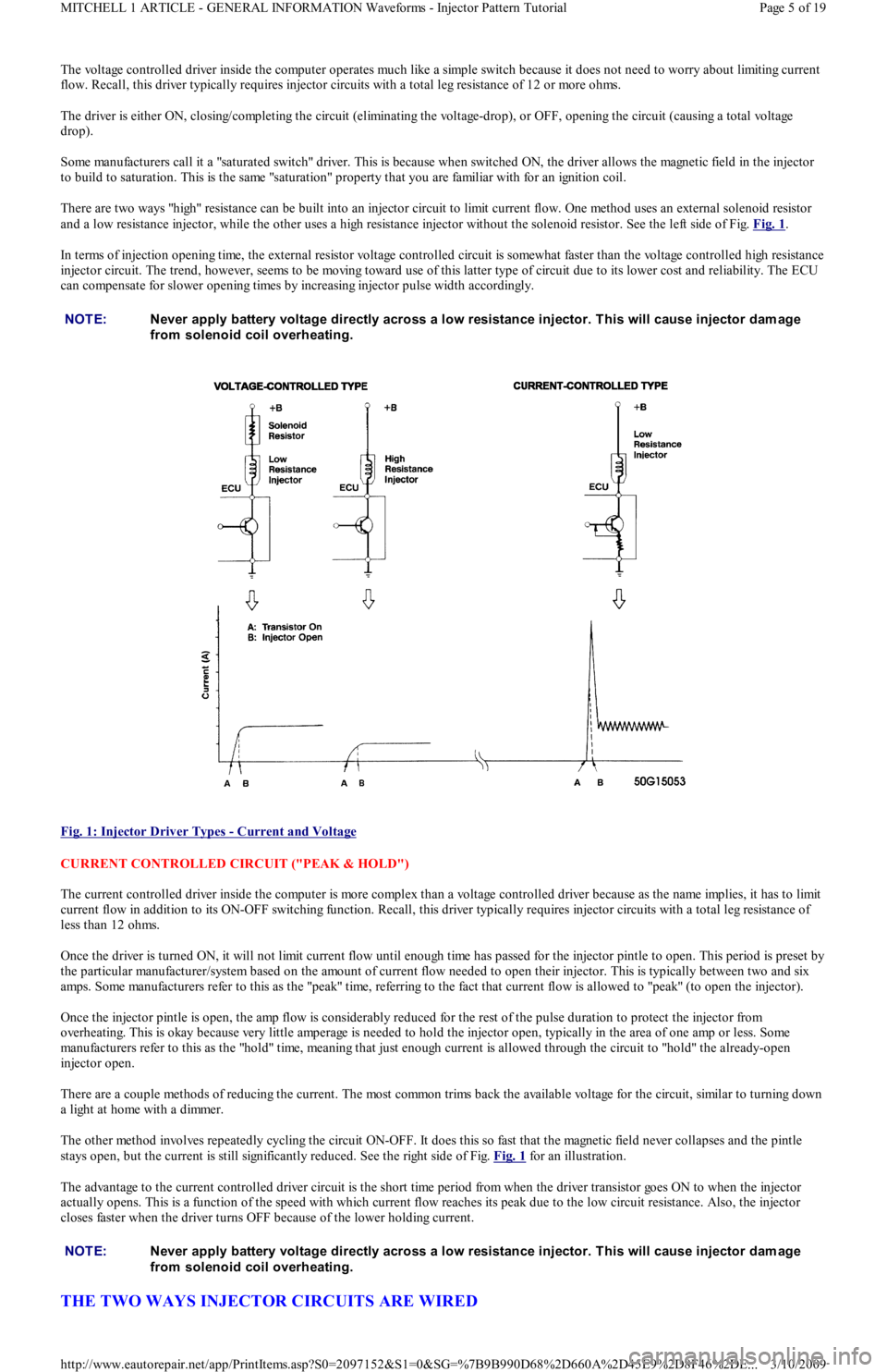
There are two ways "high" resistance can be built into an injector circuit to limit current flow. One method uses an external solenoid resistor
and a low resistance injector, while the other uses a high resistance injector without the solenoid resistor. See the left side of Fig. Fig. 1
.
In terms of injection opening time, the external resistor voltage controlled circuit is somewhat faster than the voltage controlled high resistance
injector circuit. The trend, however, seems to be moving toward use of this latter type of circuit due to its lower cost and reliability. The ECU
can compensate for slower opening times by increasing injector pulse width accordingly.
Fig. 1: Injector Driver Types
- Current and Voltage
CURRENT CONTROLLED CIRCUIT ("PEAK & HOLD")
The current controlled driver inside the computer is more complex than a voltage controlled driver because as the name implies, it has to limit
current flow in addition to its ON-OFF switching function. Recall, this driver typically requires injector circuits with a total leg resistance of
less than 12 ohms.
Once the driver is turned ON, it will not limit current flow until enough time has passed for the injector pintle to open. This period is preset by
the particular manufacturer/system based on the amount of current flow needed to open their injector. This is typically between two and six
amps. Some manufacturers refer to this as the "peak" time, referring to the fact that current flow is allowed to "peak" (to open the injector).
Once the injector pintle is open, the amp flow is considerably reduced for the rest of the pulse duration to protect the injector from
overheating. This is okay because very little amperage is needed to hold the injector open, typically in the area of one amp or less. Some
manufacturers refer to this as the "hold" time, meaning that just enough current is allowed through the circuit to "hold" the already-open
injector open.
There are a couple methods of reducing the current. The most common trims back the available voltage for the circuit, similar to turning down
a light at home with a dimmer.
The other method involves repeatedly cycling the circuit ON-OFF. It does this so fast that the magnetic field never collapses and the pintle
stays open, but the current is still significantly reduced. See the right side of Fig. Fig. 1
for an illustration.
The advantage to the current controlled driver circuit is the short time period from when the driver transistor goes ON to when the injector
actually opens. This is a function of the speed with which current flow reaches its peak due to the low circuit resistance. Also, the injector
closes faster when the driver turns OFF because of the lower holding current.
THE TWO WAYS INJECTOR CIRCUITS ARE WIRED
NOTE:Never apply battery voltage directly across a low resistance injector. T his will cause injector dam age
from solenoid coil overheating.
NOTE:Never apply battery voltage directly across a low resistance injector. T his will cause injector dam age
from solenoid coil overheating.
Page 5 of 19 MITCHELL 1 ARTICLE - GENERAL INFORMATION Waveforms - Injector Pattern Tutorial
3/10/2009 http://www.eautorepair.net/app/PrintItems.asp?S0=2097152&S1=0&SG=%7B9B990D68%2D660A%2D45E9%2D8F46%2DE
...
Page 287 of 454
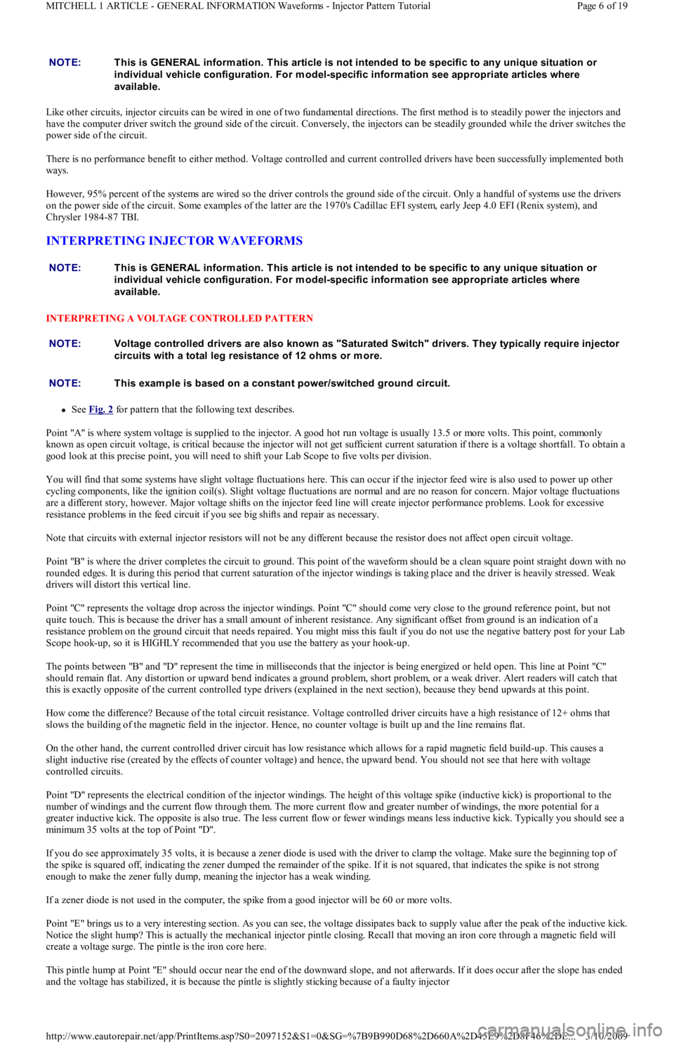
Like other circuits, injector circuits can be wired in one of two fundamental directions. The first method is to steadily power the injectors and
have the computer driver switch the ground side of the circuit. Conversely, the injectors can be steadily grounded while the driver switches the
power side of the circuit.
There is no performance benefit to either method. Voltage controlled and current controlled drivers have been successfully implemented both
ways.
However, 95% percent of the systems are wired so the driver controls the ground side of the circuit. Only a handful of systems use the drivers
on the power side of the circuit. Some examples of the latter are the 1970's Cadillac EFI system, early Jeep 4.0 EFI (Renix system), and
Chrysler 1984-87 TBI.
INTERPRETING INJECTOR WAVEFORMS
INTERPRETING A VOLTAGE CONTROLLED PATTERN
See Fig. 2 for pattern that the following text describes.
Point "A" is where system voltage is supplied to the injector. A good hot run voltage is usually 13.5 or more volts. This point, commonly
known as open circuit voltage, is critical because the injector will not get sufficient current saturation if there is a voltage shortfall. To obtain a
good look at this precise point, you will need to shift your Lab Scope to five volts per division.
You will find that some systems have slight voltage fluctuations here. This can occur if the injector feed wire is also used to power up other
cycling components, like the ignition coil(s). Slight voltage fluctuations are normal and are no reason for concern. Major voltage fluctuations
are a different story, however. Major voltage shifts on the injector feed line will create injector performance problems. Look for excessive
resistance problems in the feed circuit if you see big shifts and repair as necessary.
Note that circuits with external injector resistors will not be any different because the resistor does not affect open circuit voltage.
Point "B" is where the driver completes the circuit to ground. This point of the waveform should be a clean square point straight down with no
rounded edges. It is during this period that current saturation of the injector windings is taking place and the driver is heavily stressed. Weak
drivers will distort this vertical line.
Point "C" represents the voltage drop across the injector windings. Point "C" should come very close to the ground reference point, but not
quite touch. This is because the driver has a small amount of inherent resistance. Any significant offset from ground is an indication of a
resistance problem on the ground circuit that needs repaired. You might miss this fault if you do not use the negative battery post for your Lab
Scope hook-up, so it is HIGHLY recommended that you use the battery as your hook-up.
The points between "B" and "D" represent the time in milliseconds that the injector is being energized or held open. This line at Po int "C"
should remain flat. Any distortion or upward bend indicates a ground problem, short problem, or a weak driver. Alert readers will catch that
this is exactly opposite of the current controlled type drivers (explained in the next section), because they bend upwards at this point.
How come the difference? Because of the total circuit resistance. Voltage controlled driver circuits have a high resistance of 12+ ohms that
slows the building of the magnetic field in the injector. Hence, no counter voltage is built up and the line remains flat.
On the other hand, the current controlled driver circuit has low resistance which allows for a rapid magnetic field build-up. This causes a
slight inductive rise (created by the effects of counter voltage) and hence, the upward bend. You should not see that here with voltage
controlled circuits.
Point "D" represents the electrical condition of the injector windings. The height of this voltage spike (inductive kick) is proportional to the
number of windings and the current flow through them. The more current flow and greater number of windings, the more potential fo r a
greater inductive kick. The opposite is also true. The less current flow or fewer windings means less inductive kick. Typically you should see a
min imu m 3 5 vo l t s at t h e t o p o f Po in t "D".
If you do see approximately 35 volts, it is because a zener diode is used with the driver to clamp the voltage. Make sure the beginning top of
the spike is squared off, indicating the zener dumped the remainder of the spike. If it is not squared, that indicates the spike is not strong
enough to make the zener fully dump, meaning the injector has a weak winding.
If a zener diode is not used in the computer, the spike from a good injector will be 60 or more volts.
Point "E" brings us to a very interesting section. As you can see, the voltage dissipates back to supply value after the peak of the inductive kick.
Notice the slight hump? This is actually the mechanical injector pintle closing. Recall that moving an iron core through a magnetic field will
create a voltage surge. The pintle is the iron core here.
This pintle hump at Point "E" should occur near the end of the downward slope, and not afterwards. If it does occur after the slope has ended
and the voltage has stabilized, it is because the pintle is slightly sticking because of a faulty injector NOTE:This is GENERAL inform ation. This article is not intended to be specific to any unique situation or
individual vehicle configuration. For m odel-specific inform ation see appropriate articles where
available.
NOTE:This is GENERAL inform ation. This article is not intended to be specific to any unique situation or
individual vehicle configuration. For m odel-specific inform ation see appropriate articles where
available.
NOTE:Voltage controlled drivers are also known as "Saturated Switch" drivers. T hey typically require injector
circuits with a total leg resistance of 12 ohm s or m ore.
NOTE:T his exam ple is based on a constant power/switched ground circuit.
Page 6 of 19 MITCHELL 1 ARTICLE - GENERAL INFORMATION Waveforms - Injector Pattern Tutorial
3/10/2009 http://www.eautorepair.net/app/PrintItems.asp?S0=2097152&S1=0&SG=%7B9B990D68%2D660A%2D45E9%2D8F46%2DE
...
Page 288 of 454
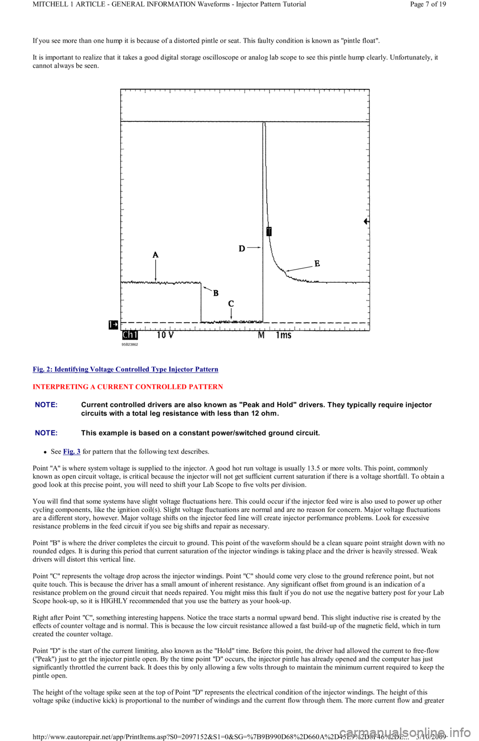
If you see more than one hump it is because of a distorted pintle or seat. This faulty condition is known as "pintle float".
It is important to realize that it takes a good digital storage oscilloscope or analog lab scope to see this pintle hump clearly. Unfortunately, it
cannot always be seen.
Fig. 2: Identifying Voltage Controlled Type Injector Pattern
INTERPRETING A CURRENT CONTROLLED PATTERN
See Fig. 3 for pattern that the following text describes.
Point "A" is where system voltage is supplied to the injector. A good hot run voltage is usually 13.5 or more volts. This point, commonly
known as open circuit voltage, is critical because the injector will not get sufficient current saturation if there is a voltage shortfall. To obtain a
good look at this precise point, you will need to shift your Lab Scope to five volts per division.
You will find that some systems have slight voltage fluctuations here. This could occur if the injector feed wire is also used to power up other
cycling components, like the ignition coil(s). Slight voltage fluctuations are normal and are no reason for concern. Major voltage fluctuations
are a different story, however. Major voltage shifts on the injector feed line will create injector performance problems. Look for excessive
resistance problems in the feed circuit if you see big shifts and repair as necessary.
Point "B" is where the driver completes the circuit to ground. This point of the waveform should be a clean square point straight down with no
rounded edges. It is during this period that current saturation of the injector windings is taking place and the driver is heavily stressed. Weak
drivers will distort this vertical line.
Point "C" represents the voltage drop across the injector windings. Point "C" should come very close to the ground reference point, but not
quite touch. This is because the driver has a small amount of inherent resistance. Any significant offset from ground is an indication of a
resistance problem on the ground circuit that needs repaired. You might miss this fault if you do not use the negative battery post for your Lab
Scope hook-up, so it is HIGHLY recommended that you use the battery as your hook-up.
Right after Point "C", something interesting happens. Notice the trace starts a normal upward bend. This slight inductive rise is created by the
effects of counter voltage and is normal. This is because the low circuit resistance allowed a fast build-up of the magnetic field, which in turn
created the counter voltage.
Point "D" is the start of the current limiting, also known as the "Hold" time. Before this point, the driver had allowed the curren t t o free-fl o w
("Peak") just to get the injector pintle open. By the time point "D" occurs, the injector pintle has already opened and the computer has just
significantly throttled the current back. It does this by only allowing a few volts through to maintain the minimum current required to keep the
pintle open.
The height of the voltage spike seen at the top of Point "D" represents the electrical condition of the injector windings. The height of this
voltage spike (inductive kick) is proportional to the number of windings and the current flow through them. The more current flow and greater
NOTE:Current controlled drivers are also known as "Peak and Hold" drivers. T hey typically require injector
circuits with a total leg resistance with less than 12 ohm .
NOTE:T his exam ple is based on a constant power/switched ground circuit.
Page 7 of 19 MITCHELL 1 ARTICLE - GENERAL INFORMATION Waveforms - Injector Pattern Tutorial
3/10/2009 http://www.eautorepair.net/app/PrintItems.asp?S0=2097152&S1=0&SG=%7B9B990D68%2D660A%2D45E9%2D8F46%2DE
...