1991 FORD FESTIVA cooling
[x] Cancel search: coolingPage 6 of 454
2. Lift access plate and disconnect sending unit wiring. To relieve fuel pressure, start engine and run it until engine stalls. Turn ignition off.
Disconnect and plug fuel lines at sending unit. Remove sending u n it a t t a c h in g sc r e ws. R e mo ve se n d in g u n it . To in st a l l , r e ve r se removal
procedure.
TACHOMETER
Removal & Installation
Remo ve in st ru men t p an el . See INSTRUMENT PANEL under REMOVAL & INSTALLATION. Disassemble panel and remove tachometer.
To install tachometer, reverse removal procedure. On Capri, the tachometer/speedometer/boost gauge assembly must be replaced as an
assembly.
TEMPERATURE GAUGE
Removal & Installation
Remo ve in st ru men t p an el . See INSTRUMENT PANEL under REMOVAL & INSTALLATION. Disassemble panel and remove temperature
gauge. To install gauge, reverse removal procedure. On Capri, the temperature/oil pressure gauge assembly must be replaced as an assembly.
TEMPERATURE SENDING UNIT
Removal
Disconnect sending unit wire, located on side of block below thermostat housing (Festiva) or cylinder head (Capri). Remove radiator cap to
relieve cooling system pressure. Position drain pan below sending unit. Remove temperature sending unit.
Installation
To install, apply Pipe Sealant With Teflon (D8AZ-19554-A) to threads of sending unit. Reverse removal procedure to complete installation.
Fill cooling system to proper level. Start engine and check for coolant leaks at sending unit.
WIRING DIAGRAMS
CAUT ION: T achom eter is calibrated at factory. Rough handling could disturb calibration.
NOTE:Refer to the appropriate WIRING DIAGRAMS article in the WIRING DIAGRAMS section.
Copyr ight 2009 Mitchell Repair Information Company, LLC. All Rights Reserved.
Article GUID: A00028301
Page 5 of 5 MITCHELL 1 ARTICLE - INSTRUMENT PANEL 1991 ACCESSORIES & SAFETY EQUIPMENT Ford Motor Co. Switches
...
3/10/2009 http://www.eautorepair.net/app/PrintItems.asp?S0=2097152&S1=0&SG=%7B959286D2%2D3A85%2D4BFC%2D9C5C%2D
...
Page 46 of 454

Back To Article
ELECT RICAL COMPONENT LOCAT OR
1991-92 ELECT RICAL COMPONENT LOCAT ION Ford Motor Co. Electrical Com ponents
BUZZERS, RELAYS & TIMERS
BUZZERS, RELAYS & TIMERS LOCATION
CIRCUIT PROTECTION DEVICES
CIRCUIT PROTECTION DEVICES LOCATION
CONTROL UNITS
CONTROL UNITS LOCATION
SENDING UNITS & SENSORS
SENDING UNITS & SENSORS LOCATION
MOTORS
MOTORS LOCATION
ComponentLocation
A/C Clutch Relay (1991)On right front of engine bay, near power
steering pump.
A/C RelayOn left front corner of engine bay, left of
cooling fan. See Fig. 1
& Fig. 2
A/C Wide Open Throttle (WAC) RelayOn left front corner of engine bay, left of
cooling fan. See Fig. 1
& Fig. 2 .
Cooling Fan RelayOn left front fender panel, near
headlight. See Fig. 1
& Fig. 2 .
Condenser Fan RelayOn left front of engine bay, left of
cooling fan. See Fig. 1
& Fig. 2 .
Daytime Running Light (DRL) Relay (Canada) (1992)On left front corner of engine bay, near
headlight. See Fig. 1
.
Fuel Pump RelayBehind left side of dash, near ECA.
Headlight RelayBehind left headlight. See Fig. 1 .
Horn RelayUnder left side of dash. See Fig. 3 .
Main RelayIn left front corner of engine bay, near
battery.
P a r kin g Ligh t R e l a yOn right front corner of engine bay. See
Fig. 1
.
Turn Signal/Flasher RelayUnder left side of dash, behind ECA.
See Fig. 3
.
ComponentLocation
A/C In-Line FuseOn left side of heater case.
Condenser Fan In-Line FuseOn right side of steering column.
Fuse PanelBehind access panel, to left of steering column.
Fusible LinksOn left front strut tower. See Fig. 1 .
ComponentLocation
Electronic Control Assembly (ECA)Behind left side of dash, left of steering column.
Passive Restraint ModuleUnder driver's seat.
ComponentLocation
Airflow MeterOn right front corner of engine bay. See Fig. 1 .
Coolant Temperature Sending UnitBelow thermostat housing.
Crankshaft Position SensorInside distributor. See Fig. 1 .
EGR Temperature Sensor (1991)In exhaust manifold, near EGR valve.
Engine Coolant Temperature (ECT) SensorOn top of engine, near injector No. 1.
Fuel Gauge Sending Unit (1992)In fu el t an k.
Throttle Position Sensor (TPS)On left side of throttle body. See Fig. 1 .
ComponentLocation
Blower MotorUnder center of dash, behind
radio.
Windshield Washer Motors:
Front (1991)On right front fender panel,
bottom of washer reservoir.
Front (1992)On left front corner of engine
bay, in front of battery.
RearOn body panel, behind right
rear quarter panel.
Windshield Wiper Motor
Page 1 of 3 MITCHELL 1 ARTICLE - ELECTRICAL COMPONENT LOCATOR 1991-92 ELECTRICAL COMPONENT LOCATION For...
3/10/2009 http://www.eautorepair.net/app/PrintItems.asp?S0=2097152&S1=0&SG=%7B959286D2%2D3A85%2D4BFC%2D9C5C%2D
...
Page 47 of 454
SOLENOIDS & SOLENOID VALVES
SOLENOIDS & SOLENOID VALVES LOCATION
SWITCHES
SWITCHES LOCATION
MISCELLANEOUS
MISCELLANEOUS LOCATION
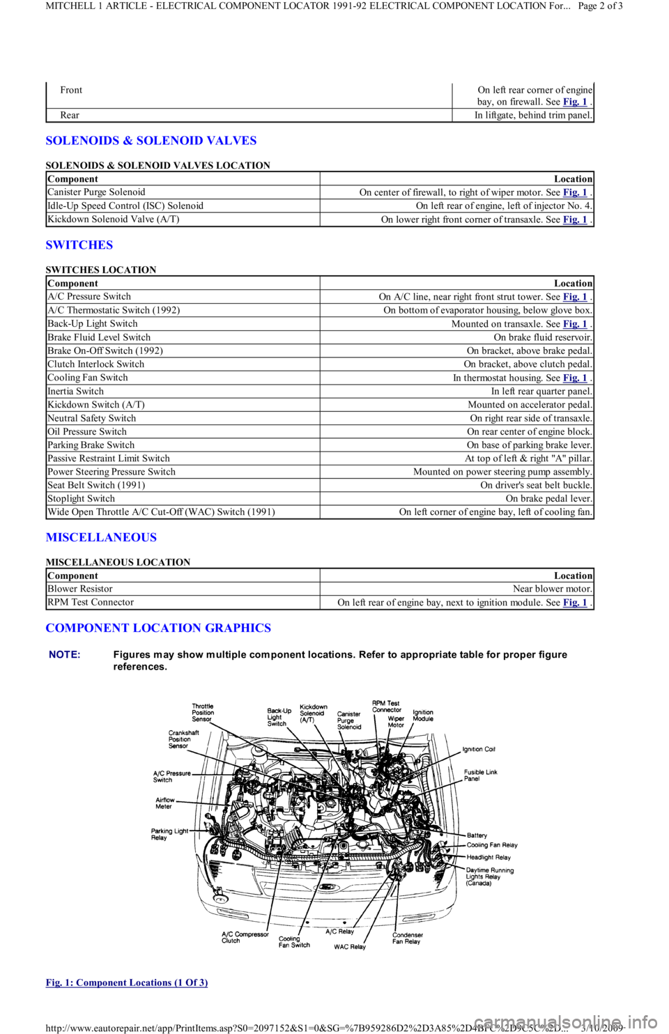
COMPONENT LOCATION GRAPHICS
Fig. 1: Component Locations (1 Of 3)
FrontOn left rear corner of engine
bay, on firewall. See Fig. 1
.
RearIn liftgate, behind trim panel.
ComponentLocation
Canister Purge SolenoidOn center of firewall, to right of wiper motor. See Fig. 1 .
Idle-Up Speed Control (ISC) SolenoidOn left rear of engine, left of injector No. 4.
Kickdown Solenoid Valve (A/T)On lower right front corner of transaxle. See Fig. 1 .
ComponentLocation
A/C Pressure SwitchOn A/C line, near right front strut tower. See Fig. 1 .
A/C Thermostatic Switch (1992)On bottom of evaporator housing, below glove box.
Back-Up Light SwitchMounted on transaxle. See Fig. 1 .
Brake Fluid Level SwitchOn brake fluid reservoir.
Brake On-Off Switch (1992)On bracket, above brake pedal.
Clutch Interlock SwitchOn bracket, above clutch pedal.
Cooling Fan SwitchIn thermostat housing. See Fig. 1 .
Inertia SwitchIn left rear quarter panel.
Kickdown Switch (A/T)Mounted on accelerator pedal.
Neutral Safety SwitchOn right rear side of transaxle.
Oil Pressure SwitchOn rear center of engine block.
Parking Brake SwitchOn base of parking brake lever.
Passive Restraint Limit SwitchAt top of left & right "A" pillar.
Power Steering Pressure SwitchMounted on power steering pump assembly.
Seat Belt Switch (1991)On driver's seat belt buckle.
Stoplight SwitchOn brake pedal lever.
Wide Open Throttle A/C Cut-Off (WAC) Switch (1991)On left corner of engine bay, left of cooling fan.
ComponentLocation
Blower ResistorNear blower motor.
RPM Test ConnectorOn left rear of engine bay, next to ignition module. See Fig. 1 .
NOTE:Figures m ay show m ultiple com ponent locations. Refer to appropriate table for proper figure
references.
Page 2 of 3 MITCHELL 1 ARTICLE - ELECTRICAL COMPONENT LOCATOR 1991-92 ELECTRICAL COMPONENT LOCATION For...
3/10/2009 http://www.eautorepair.net/app/PrintItems.asp?S0=2097152&S1=0&SG=%7B959286D2%2D3A85%2D4BFC%2D9C5C%2D
...
Page 49 of 454
Back To Article
FUSES & CIRCUIT BREAKERS
Fuses & Circuit Breakers 1988-93 Festiva
FUSES & FUSIBLE LINKS
FUSE PANEL & FUSIBLE LINK BLOCK LOCATIONS
The vehicle has a fuse block with fusible links and a fuse panel with circuit fuses. The fuse panel is located behind the instrument panel, left o
f
the steering column. The fuse block is located under the hood.
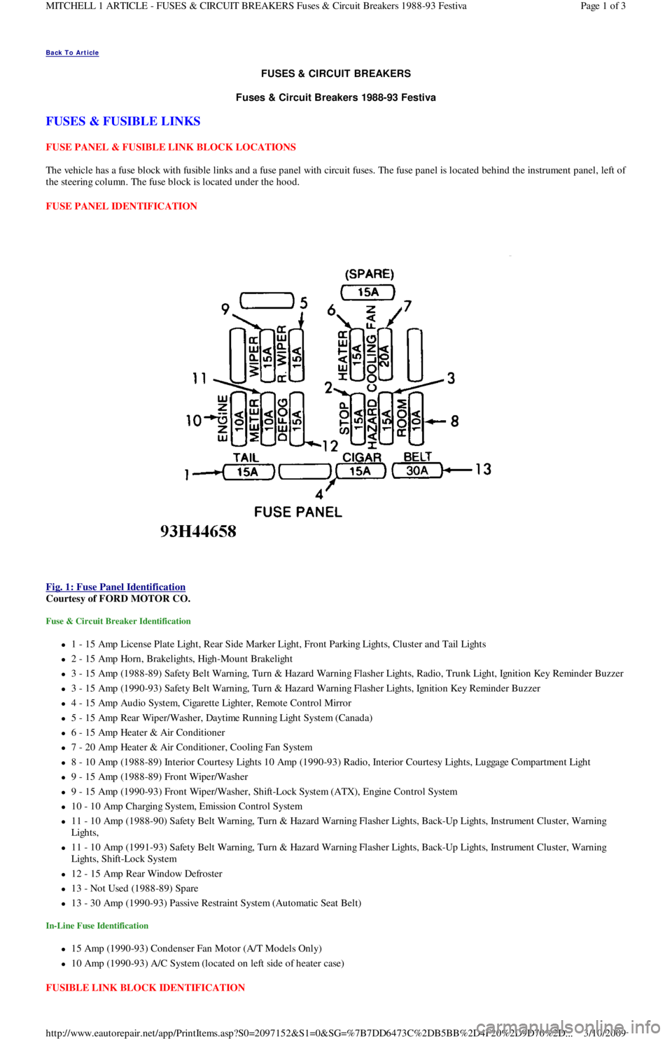
FUSE PANEL IDENTIFICATION
Fig. 1: Fuse Panel Identification
Courtesy of FORD MOTOR CO.
Fuse & Circuit Breaker Identification
1 - 15 Amp License Plate Light, Rear Side Marker Ligh t , Fr o n t P a r kin g Ligh t s, C l u st e r a n d Ta il Ligh t s
2 - 15 Amp Horn, Brakelights, High-Mount Brakelight
3 - 15 Amp (1988-89) Safety Belt Warning, Turn & Hazard Warning Flasher Lights, Radio, Trunk Light, Ignition Key Reminder Buzzer
3 - 15 Amp (1990-93) Safety Belt Warning, Turn & Hazard Warning Flasher Lights, Ignition Key Reminder Buzzer
4 - 15 Amp Audio System, Cigarette Lighter, Remote Control Mirror
5 - 15 Amp Rear Wiper/Washer, Daytime Running Light System (Canada)
6 - 15 Amp Heater & Air Conditioner
7 - 20 Amp Heater & Air Conditioner, Cooling Fan System
8 - 10 Amp (1988-89) Interior Courtesy Lights 10 Amp (1990-93) Radio, Interior Courtesy Lights, Luggage Compartment Light
9 - 15 Amp (1988-89) Front Wiper/Washer
9 - 15 Amp (1990-93) Front Wiper/Washer, Shift-Lock System (ATX), Engine Control System
10 - 10 Amp Charging System, Emission Control System
11 - 10 Amp (1988-90) Safety Belt Warning, Turn & Hazard Warning Flasher Lights, Back-Up Lights, Instrument Cluster, Warning
Lights,
11 - 10 Amp (1991-93) Safety Belt Warning, Turn & Hazard Warning Flasher Lights, Back-Up Lights, Instrument Cluster, Warning
Lights, Shift-Lock System
12 - 15 Amp Rear Window Defroster
13 - Not Used (1988-89) Spare
13 - 30 Amp (1990-93) Passive Restraint System (Automatic Seat Belt)
In-Line Fuse Identification
15 Amp (1990-93) Condenser Fan Motor (A/T Models Only)
10 Amp (1990-93) A/C System (located on left side of heater case)
FUSIBLE LINK BLOCK IDENTIFICATION
Page 1 of 3 MITCHELL 1 ARTICLE - FUSES & CIRCUIT BREAKERS Fuses & Circuit Breakers 1988-93 Festiva
3/10/2009 http://www.eautorepair.net/app/PrintItems.asp?S0=2097152&S1=0&SG=%7B7DD6473C%2DB5BB%2D4F20%2D9D70%2D
...
Page 50 of 454
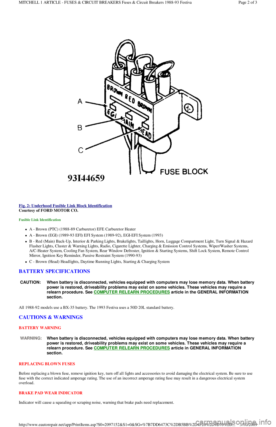
Fig. 2: Underhood Fusible Link Block Identification
Courtesy of FORD MOTOR CO.
Fusible Link Identification
A - Brown (PTC) (1988-89 Carburetor) EFE Carburetor Heater
A - Brown (EGI) (1989-93 EFI) EFI System (1989-92), EGI-EFI System (1993)
B - Red (Main) Back-Up, Interior & Parking Lights, Brakelights, Taillights, Horn, Luggage Compartment Light, Turn Signal & Hazard
F l a sh e r Ligh t s, C l u st e r & Wa r n in g Ligh t s, R a d io , C iga r e t t e Ligh t e r , C h a r gin g & E missio n C o n t r o l S yst e ms, Wip e r / Wa sh e r S yst e ms,
A/C-Heater System, Cooling Fan System, Rear Window Defroster, Ignition & Starting Systems, Shift Lock System, Remote Control
Mirror, Ignition Key Reminder, Passive Restraint System (1990-93)
C - Brown (Head) Headlights, Daytime Running Lights, Starting & Charging System
BATTERY SPECIFICATIONS
All 1988-92 models use a BX-35 battery. The 1993 Festiva uses a 50D 20L standard battery.
CAUTIONS & WARNINGS
BATTERY WARNING
REPLACING BLOWN FUSES
Before replacing a blown fuse, remove ignition key, turn off all lights and accessories to avoid damaging the electrical system. Be sure to use
fuse with the correct indicated amperage rating. The use of an incorrect amperage rating fuse may result in a dangerous electrical system
overload.
BRAKE PAD WEAR INDICATOR
Indicator will cause a squealing or scraping noise, warning that brake pads need replacement.
CAUT ION: When battery is disconnected, vehicles equipped with com puters m ay lose m em ory data. When battery
power is restored, driveability problem s m ay exist on som e vehicles. T hese vehicles m ay require a
relearn procedure. See COMPUTER RELEARN PROCEDURES
article in the GENERAL INFORMAT ION
section.
WARNING:When battery is disconnected, vehicles equipped with com puters m ay lose m em ory data. When battery
power is restored, driveability problem s m ay exist on som e vehicles. T hese vehicles m ay require a
relearn procedure. See COMPUTER RELEARN PROCEDURES
article in GENERAL INFORMAT ION
section.
Page 2 of 3 MITCHELL 1 ARTICLE - FUSES & CIRCUIT BREAKERS Fuses & Circuit Breakers 1988-93 Festiva
3/10/2009 http://www.eautorepair.net/app/PrintItems.asp?S0=2097152&S1=0&SG=%7B7DD6473C%2DB5BB%2D4F20%2D9D70%2D
...
Page 51 of 454
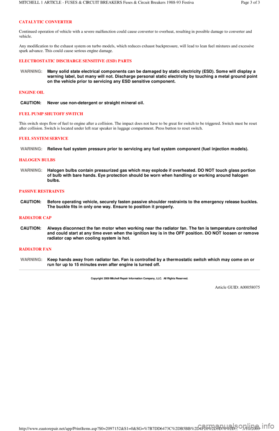
CATALYTIC CONVERTER
Continued operation of vehicle with a severe malfunction could cause converter to overheat, resulting in possible damage to converter and
ve h ic l e .
Any modification to the exhaust system on turbo models, which reduces exhaust backpressure, will lead to lean fuel mixtures and excessive
spark advance. This could cause serious engine damage.
ELECTROSTATIC DISCHARGE SENSITIVE (ESD) PARTS
ENGINE OIL
FUEL PUMP SHUTOFF SWITCH
This switch stops flow of fuel to engine after a collision. The impact does not have to be great for switch to be triggered. Switch must be reset
after collision. Switch is located under left rear speaker in luggage compartment. Press button to reset switch.
FUEL SYSTEM SERVICE
HALOGEN BULBS
PASSIVE RESTRAINTS
RADIATOR CAP
RADIATOR FAN WARNING:Many solid state electrical com ponents can be dam aged by static electricity (ESD). Som e will display a
warning label, but m any will not. Discharge personal static electricity by touching a m etal ground point
on the vehicle prior to servicing any ESD sensitive com ponent.
CAUT ION: Never use non-detergent or straight m ineral oil.
WARNING:Relieve fuel system pressure prior to servicing any fuel system com ponent (fuel injection m odels).
WARNING:Halogen bulbs contain pressurized gas which m ay explode if overheated. DO NOT touch glass portion
of bulb with bare hands. Eye protection should be worn when handling or working around halogen
bulbs.
CAUT ION: Before operating vehicle, securely fasten passive shoulder restraints to the em ergency release buckles.
T he buckle fits in only one way. Ensure to position it properly.
CAUT ION: Always disconnect the fan m otor when working near the radiator fan. T he fan is tem perature controlled
and could start at any tim e even when the ignition key is in the OFF position. DO NOT loosen or rem ove
radiator cap when cooling system is hot.
WARNING:Keep hands away from radiator fan. Fan is controlled by a therm ostatic switch which m ay com e on or
run for up to 15 m inutes even after engine is turned off.
Copyr ight 2009 Mitchell Repair Information Company, LLC. All Rights Reserved.
Article GUID: A00058075
Page 3 of 3 MITCHELL 1 ARTICLE - FUSES & CIRCUIT BREAKERS Fuses & Circuit Breakers 1988-93 Festiva
3/10/2009 http://www.eautorepair.net/app/PrintItems.asp?S0=2097152&S1=0&SG=%7B7DD6473C%2DB5BB%2D4F20%2D9D70%2D
...
Page 58 of 454
Back To Article
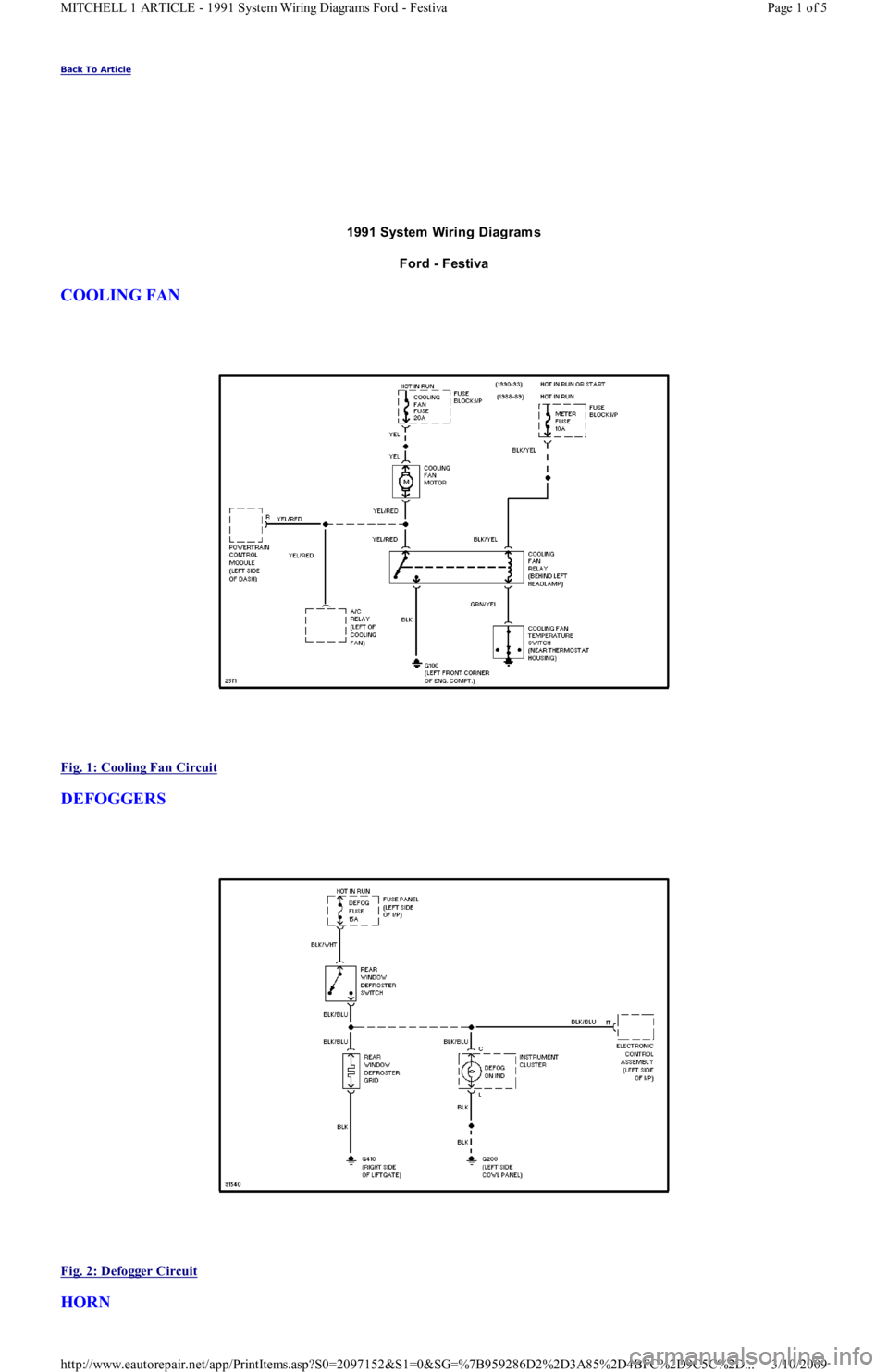
1991 System Wiring Diagram s
Ford - Festiva
COOLING FAN
Fig. 1: Cooling Fan Circuit
DEFOGGERS
Fig. 2: Defogger Circuit
HORN
Page 1 of 5 MITCHELL 1 ARTICLE - 1991 System Wiring Diagrams Ford - Festiva
3/10/2009 http://www.eautorepair.net/app/PrintItems.asp?S0=2097152&S1=0&SG=%7B959286D2%2D3A85%2D4BFC%2D9C5C%2D
...
Page 63 of 454
Back To Article
GENERAL INFORMATION
Using Mitchell1's Wiring Diagram s
INTRODUCTION
Mitchell1(R) obtains wiring diagrams and technical service bulletins, containing wiring diagram changes, from the domestic and import
manufacturers. These are checked for accuracy and are all redrawn into a consistent format for easy use. All system wiring diagrams are
available in color format and may be viewed and or printed in color or black and white, depending on your program settings and available
printer hardware.
In the past, when cars were simpler, diagrams were simpler. All components were connected by wires, and diagrams seldom exceeded 4 pages
in length. Today, some wiring diagrams require more than 16 pages. It would be impractical to expect a service technician to trace a wire from
page 1 across every page to page 16.
Removing some of the wiring maze reduces eyestrain and time wasted searching across several pages. Today, the majority of Mitchell1(R)
diagrams follow a much improved format, which permits space for internal switch details, and component and ground locations.
Components shown with a dashed line instead of a solid line indicate not all circuits are shown in this particular diagram (circuits shown in
system diagrams are typically applicable to that system only). The remaining circuits connected to that component will be shown in the
appropriate system that they apply to.
Today, the wiring diagram necessary to support a given repair procedure is included within that article or a link is provided to the appropriate
SYSTEM WIRING DIAGRAM article. For example, the wiring diagram for a Ford EEC-IV system may be included in ENGINE
PERFORMANCE and WIRING DIAGRAMS articles for Ford Motor Co. The wiring diagram for a cruise control system may be included in
ACCESSORIES & EQUIPMENT section for the specific vehicle manufacturer, and the wiring diagram for an anti-lock brake system may be
included in BRAKES and WIRING DIAGRAMS for the specific manufacturer.
WIRING DIAGRAMS contains all wiring diagrams not included in STARTING & CHARGING SYSTEMS and ACCESSORIES &
EQUIPMENT. This includes: Data Link Connectors, Ground Distribution, Power Distribution, Engine Performance, Electric Cooling Fans,
Anti-Lock Brakes, Electronic Suspension and Electronic Steering wiring diagrams. The Data Link Connectors wiring diagrams show the
circuits by which the various on-board computers exchange information, and the diagnostic connectors used for diagnosis and their location.
The Ground Distribution wiring diagrams show all vehicle ground points, their location, and the components common to those ground points.
The Power Distribution wiring diagrams show the power feed circuits and the components common to those power feeds.
Wiring diagrams used to support the information in ACCESSORIES & EQUIPMENT are drawn in a "top-down" format. The diagrams are
drawn with the power source at the top of the diagram and the ground point at the bottom of the diagram. Component locations are identified
on the wiring diagrams. Any wires that do not connect directly to a component are identified on the diagram to indicate where they go.
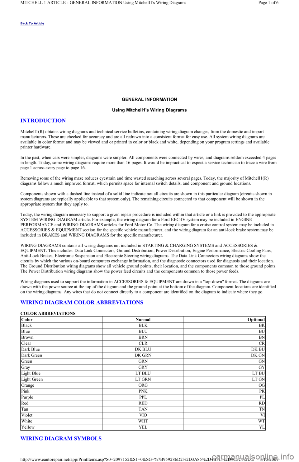
WIRING DIAGRAM COLOR ABBREVIATIONS
COLOR ABBREVIATIONS
WIRING DIAGRAM SYMBOLS
ColorNormalOptional
BlackBLKBK
BlueBLUBU
BrownBRNBN
ClearCLRCR
Dark BlueDK BLUDK BU
Dark GreenDK GRNDK GN
GreenGRNGN
GrayGRYGY
Light BlueLT BLULT BU
Light GreenLT GRNLT GN
OrangeORGOG
PinkPNKPK
PurplePPLPL
RedREDRD
TanTANTN
VioletVIOVI
WhiteWHTWT
YellowYELYL
Page 1 of 6 MITCHELL 1 ARTICLE - GENERAL INFORMATION Using Mitchell1's Wiring Diagrams
3/10/2009 http://www.eautorepair.net/app/PrintItems.asp?S0=2097152&S1=0&SG=%7B959286D2%2D3A85%2D4BFC%2D9C5C%2D
...