1991 FORD FESTIVA fuse chart
[x] Cancel search: fuse chartPage 214 of 454
Back To Article
GENERAL INFORMATION
T rouble Shooting - Basic Procedures
* PLEASE READ THIS FIRST *
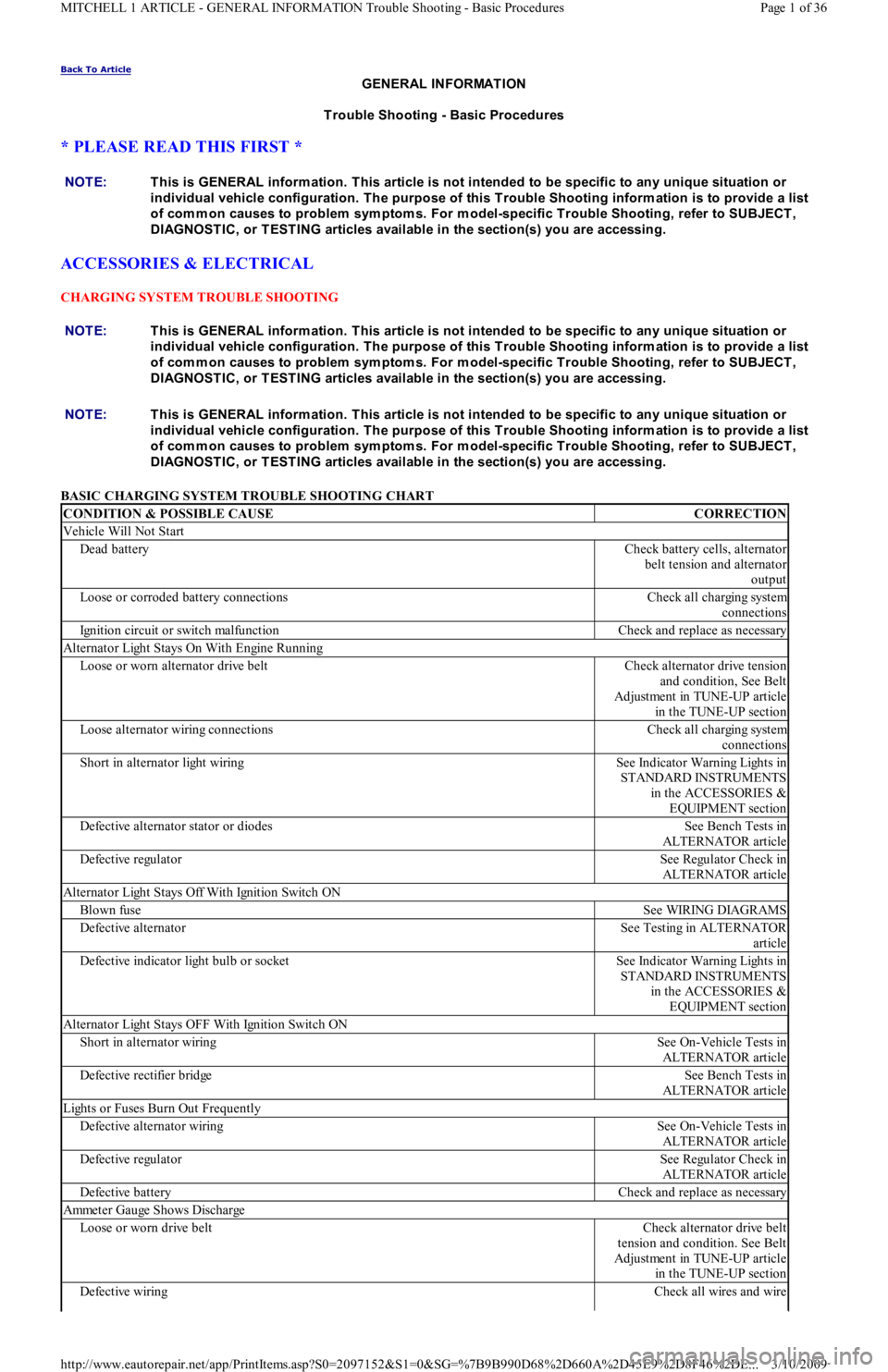
ACCESSORIES & ELECTRICAL
CHARGING SYSTEM TROUBLE SHOOTING
BASIC CHARGING SYSTEM TROUBLE SHOOTING CHART NOTE:This is GENERAL inform ation. This article is not intended to be specific to any unique situation or
individual vehicle configuration. T he purpose of this T rouble Shooting inform ation is to provide a list
of com m on causes to problem sym ptom s. For m odel-specific T rouble Shooting, refer to SUBJECT ,
DIAGNOST IC, or T EST ING articles available in the section(s) you are accessing.
NOTE:This is GENERAL inform ation. This article is not intended to be specific to any unique situation or
individual vehicle configuration. T he purpose of this T rouble Shooting inform ation is to provide a list
of com m on causes to problem sym ptom s. For m odel-specific T rouble Shooting, refer to SUBJECT ,
DIAGNOST IC, or T EST ING articles available in the section(s) you are accessing.
CONDITION & POSSIBLE CAUSECORRECTION
Vehicle Will Not Start
Dead batteryCheck battery cells, alternator
belt tension and alternator
output
Loose or corroded battery connectionsCheck all charging system
connections
Ignition circuit or switch malfunctionCheck and replace as necessary
Alternator Light Stays On With Engine Running
Loose or worn alternator drive beltCheck alternator drive tension
and condition, See Belt
Adjustment in TUNE-UP article
in the TUNE-UP section
Loose alternator wiring connectionsCheck all charging system
connections
Short in alternator light wiringSee Indicator Warning Lights in
STANDARD INSTRUMENTS
in the ACCESSORIES &
EQUIPMENT section
Defective alternator stator or diodesSee Bench Tests in
ALTERNATOR article
Defective regulatorSee Regulator Check in
ALTERNATOR article
Alternator Light Stays Off With Ignition Switch ON
Blown fuseSee WIRING DIAGRAMS
Defective alternatorSee Testing in ALTERNATOR
article
Defective indicator light bulb or socketSee Indicator Warning Lights in
STANDARD INSTRUMENTS
in the ACCESSORIES &
EQUIPMENT section
Alternator Light Stays OFF With Ignition Switch ON
Short in alternator wiringSee On-Vehicle Tests in
ALTERNATOR article
Defective rectifier bridgeSee Bench Tests in
ALTERNATOR article
Lights or Fuses Burn Out Frequently
Defective alternator wiringSee On-Vehicle Tests in
ALTERNATOR article
Defective regulatorSee Regulator Check in
ALTERNATOR article
Defective batteryCheck and replace as necessary
Ammeter Gauge Shows Discharge
Loose or worn drive beltCheck alternator drive belt
tension and condition. See Belt
Adjustment in TUNE-UP article
in the TUNE-UP section
Defective wiringCheck all wires and wire
Page 1 of 36 MITCHELL 1 ARTICLE - GENERAL INFORMATION Trouble Shooting - Basic Procedures
3/10/2009 http://www.eautorepair.net/app/PrintItems.asp?S0=2097152&S1=0&SG=%7B9B990D68%2D660A%2D45E9%2D8F46%2DE
...
Page 219 of 454
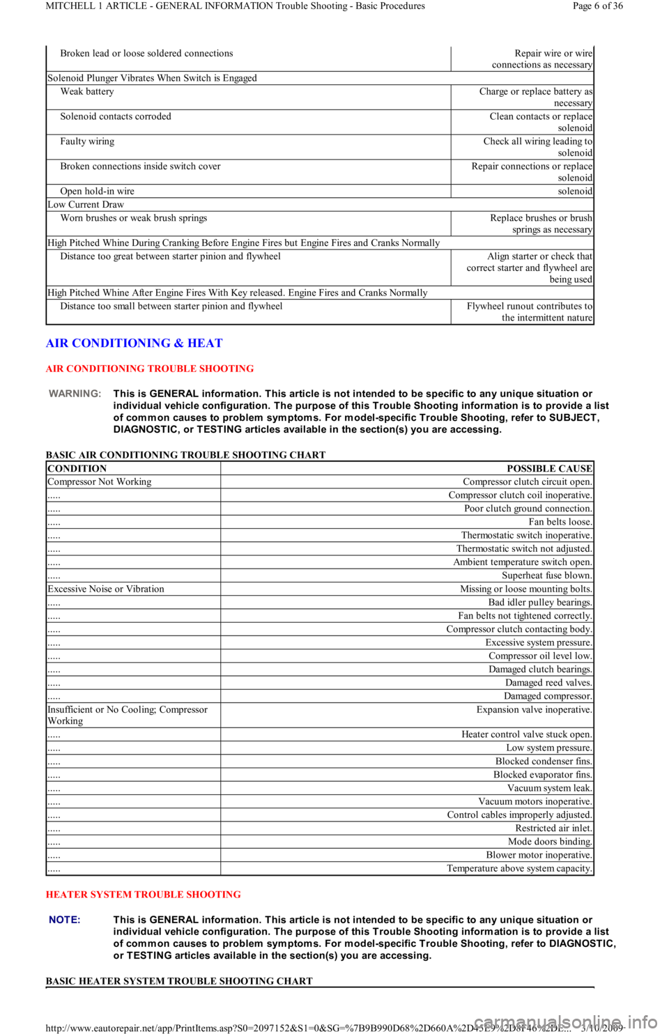
AIR CONDITIONING & HEAT
AIR CONDITIONING TROUBLE SHOOTING
BASIC AIR CONDITIONING TROUBLE SHOOTING CHART
HEATER SYSTEM TROUBLE SHOOTING
BASIC HEATER SYSTEM TROUBLE SHOOTING CHART
Broken lead or loose soldered connectionsRepair wire or wire
connections as necessary
Solenoid Plunger Vibrates When Switch is Engaged
Weak batteryCharge or replace battery as
necessary
Solenoid contacts corrodedClean contacts or replace
solenoid
Faulty wiringCheck all wiring leading to
solenoid
Broken connections inside switch coverRepair connections or replace
solenoid
Open hold-in wiresolenoid
Low Current Draw
Worn brushes or weak brush springsReplace brushes or brush
springs as necessary
High Pitched Whine During Cranking Before Engine Fires but Engine Fires and Cranks Normally
Distance too great between starter pinion and flywheelAlign starter or check that
correct starter and flywheel are
being used
High Pitched Whine After Engine Fires With Key released. Engine Fires and Cranks Normally
Distance too small between starter pinion and flywheelFlywheel runout contributes to
the intermittent nature
WARNING:This is GENERAL inform ation. This article is not intended to be specific to any unique situation or
individual vehicle configuration. T he purpose of this T rouble Shooting inform ation is to provide a list
of com m on causes to problem sym ptom s. For m odel-specific T rouble Shooting, refer to SUBJECT ,
DIAGNOST IC, or T EST ING articles available in the section(s) you are accessing.
CONDITIONPOSSIBLE CAUSE
Compressor Not WorkingCompressor clutch circuit open.
.....Compressor clutch coil inoperative.
.....Poor clutch ground connection.
.....Fan belts loose.
.....Thermostatic switch inoperative.
.....Thermostatic switch not adjusted.
.....Ambient temperature switch open.
.....Superheat fuse blown.
Excessive Noise or VibrationMissing or loose mounting bolts.
.....Bad idler pulley bearings.
.....Fan belts not tightened correctly.
.....Compressor clutch contacting body.
.....Excessive system pressure.
.....Compressor oil level low.
.....Damaged clutch bearings.
.....Damaged reed valves.
.....Damaged compressor.
In su fficien t o r No Co o l in g; Co mp resso r
WorkingExpansion valve inoperative.
.....Heater control valve stuck open.
.....Low system pressure.
.....Blocked condenser fins.
.....Blocked evaporator fins.
.....Vacuum system leak.
.....Vacuum motors inoperative.
.....Control cables improperly adjusted.
.....Restricted air inlet.
.....Mode doors binding.
.....Blower motor inoperative.
.....Temperature above system capacity.
NOTE:This is GENERAL inform ation. This article is not intended to be specific to any unique situation or
individual vehicle configuration. T he purpose of this T rouble Shooting inform ation is to provide a list
of com m on causes to problem sym ptom s. For m odel-specific T rouble Shooting, refer to DIAGNOST IC,
or T EST ING articles available in the section(s) you are accessing.
Page 6 of 36 MITCHELL 1 ARTICLE - GENERAL INFORMATION Trouble Shooting - Basic Procedures
3/10/2009 http://www.eautorepair.net/app/PrintItems.asp?S0=2097152&S1=0&SG=%7B9B990D68%2D660A%2D45E9%2D8F46%2DE
...
Page 220 of 454
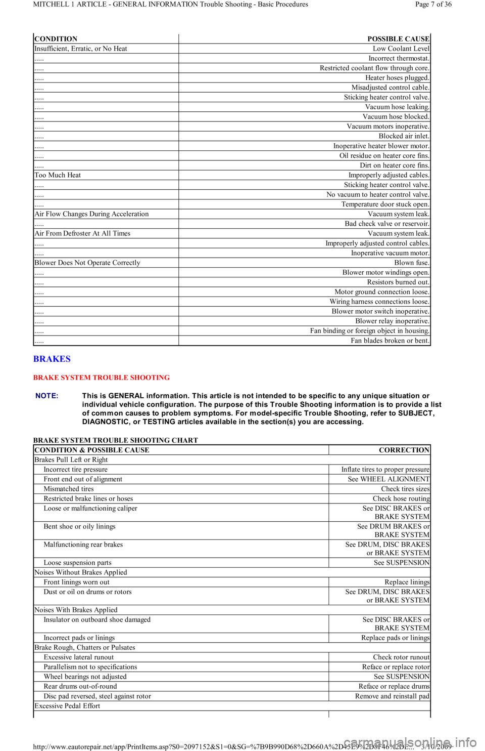
BRAKES
BRAKE SYSTEM TROUBLE SHOOTING
BRAKE SYSTEM TROUBLE SHOOTING CHART
CONDITIONPOSSIBLE CAUSE
Insufficient, Erratic, or No HeatLow Coolant Level
.....Incorrect thermostat.
.....Restricted coolant flow through core.
.....Heater hoses plugged.
.....Misadjusted control cable.
.....Sticking heater control valve.
.....Vacuum hose leaking.
.....Vacuum hose blocked.
.....Vacuum motors inoperative.
.....Blocked air inlet.
.....Inoperative heater blower motor.
.....Oil residue on heater core fins.
.....Dirt on heater core fins.
Too Much HeatImproperly adjusted cables.
.....Sticking heater control valve.
.....No vacuum to heater control valve.
.....Temperature door stuck open.
Air Flow Changes During AccelerationVacuum system leak.
.....Bad check valve or reservoir.
Air From Defroster At All TimesVacuum system leak.
.....Improperly adjusted control cables.
.....Inoperative vacuum motor.
Blower Does Not Operate CorrectlyBlown fuse.
.....Blower motor windings open.
.....Resistors burned out.
.....Motor ground connection loose.
.....Wiring harness connections loose.
.....Blower motor switch inoperative.
.....Blower relay inoperative.
.....Fan binding or foreign object in housing.
.....Fan blades broken or bent.
NOTE:This is GENERAL inform ation. This article is not intended to be specific to any unique situation or
individual vehicle configuration. T he purpose of this T rouble Shooting inform ation is to provide a list
of com m on causes to problem sym ptom s. For m odel-specific T rouble Shooting, refer to SUBJECT ,
DIAGNOST IC, or T EST ING articles available in the section(s) you are accessing.
CONDITION & POSSIBLE CAUSECORRECTION
Brakes Pull Left or Right
Incorrect tire pressureInflate tires to proper pressure
Front end out of alignmentSee WHEEL ALIGNMENT
Mismatched tiresCheck tires sizes
Restricted brake lines or hosesCheck hose routing
Loose or malfunctioning caliperSee DISC BRAKES or
BRAKE SYSTEM
Bent shoe or oily liningsSee DRUM BRAKES or
BRAKE SYSTEM
Malfunctioning rear brakesSee DRUM, DISC BRAKES
or BRAKE SYSTEM
Loose suspension partsSee SUSPENSION
Noises Without Brakes Applied
Front linings worn outReplace linings
Dust or oil on drums or rotorsSee DRUM, DISC BRAKES
or BRAKE SYSTEM
Noises With Brakes Applied
Insulator on outboard shoe damagedSee DISC BRAKES or
BRAKE SYSTEM
Incorrect pads or liningsReplace pads or linings
Brake Rough, Chatters or Pulsates
Excessive lateral runoutCheck rotor runout
Parallelism not to specificationsReface or replace rotor
Wheel bearings not adjustedSee SUSPENSION
Rear drums out-of-roundReface or replace drums
Disc pad reversed, steel against rotorRemove and reinstall pad
Excessive Pedal Effort
Page 7 of 36 MITCHELL 1 ARTICLE - GENERAL INFORMATION Trouble Shooting - Basic Procedures
3/10/2009 http://www.eautorepair.net/app/PrintItems.asp?S0=2097152&S1=0&SG=%7B9B990D68%2D660A%2D45E9%2D8F46%2DE
...
Page 234 of 454
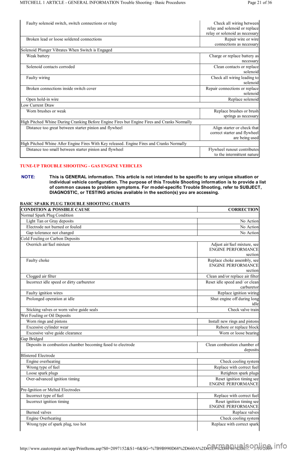
TUNE-UP TROUBLE SHOOTING - GAS ENGINE VEHICLES
BASIC SPARK PLUG TROUBLE SHOOTING CHARTS
Faulty solenoid switch, switch connections or relayCheck all wiring between
relay and solenoid or replace
relay or solenoid as necessary
Broken lead or loose soldered connectionsRepair wire or wire
connections as necessary
Solenoid Plunger Vibrates When Switch is Engaged
Weak batteryCharge or replace battery as
necessary
Solenoid contacts corrodedClean contacts or replace
solenoid
Faulty wiringCheck all wiring leading to
solenoid
Broken connections inside switch coverRepair connections or replace
solenoid
Open hold-in wireReplace solenoid
Low Current Draw
Worn brushes or weakReplace brushes or brush
springs as necessary
High Pitched Whine During Cranking Before Engine Fires but Engine Fires and Cranks Normally
Distance too great between starter pinion and flywheelAlign starter or check that
correct starter and flywheel
are being used
High Pitched Whine After Engine Fires With Key released. Engine Fires and Cranks Normally
Distance too small between starter pinion and flywheelFlywheel runout contributes
to the intermittent nature
NOTE:This is GENERAL inform ation. This article is not intended to be specific to any unique situation or
individual vehicle configuration. T he purpose of this T rouble Shooting inform ation is to provide a list
of com m on causes to problem sym ptom s. For m odel-specific T rouble Shooting, refer to SUBJECT ,
DIAGNOST IC, or T EST ING articles available in the section(s) you are accessing.
CONDITION & POSSIBLE CAUSECORRECTION
Normal Spark Plug Condition
Light Tan or Gray depositsNo Action
Electrode not burned or fouledNo Action
Gap tolerance not changedNo Action
Cold Fouling or Carbon Deposits
Overrich air/fuel mixtureAdjust air/fuel mixture, see
ENGINE PERFORMANCE
section
Faulty chokeReplace choke assembly, see
ENGINE PERFORMANCE
section
Clogged air filterClean and/or replace air filter
Incorrect idle speed or dirty carburetorReset idle speed and/ or clean
carburetor
Faulty ignition wiresReplace ignition wiring
Prolonged operation at idleShut engine off during long
idle
Sticking valves or worn valve guide sealsCheck valve train
Wet Fouling or Oil Deposits
Worn rings and pistonsInstall new rings and pistons
Excessive cylinder wearRebore or replace block
Excessive valve guide clearanceWorn or loose bearing
Gap Bridged
Deposits in combustion chamber becoming fused to electrodeClean combustion chamber of
deposits
Blistered Electrode
Engine overheatingCheck cooling system
Wrong type of fuelReplace with correct fuel
Loose spark plugsRetighten spark plugs
Over-advanced ignition timingReset ignition timing see
ENGINE PERFORMANCE
Pre-Ignition or Melted Electrodes
Incorrect type of fuelReplace with correct fuel
Incorrect ignition timingReset ignition timing see
ENGINE PERFORMANCE
Burned valvesReplace valves
Engine OverheatingCheck cooling system
Wrong type of spark plug, too hotReplace with correct spark
Page 21 of 36 MITCHELL 1 ARTICLE - GENERAL INFORMATION Trouble Shooting - Basic Procedures
3/10/2009 http://www.eautorepair.net/app/PrintItems.asp?S0=2097152&S1=0&SG=%7B9B990D68%2D660A%2D45E9%2D8F46%2DE
...
Page 278 of 454
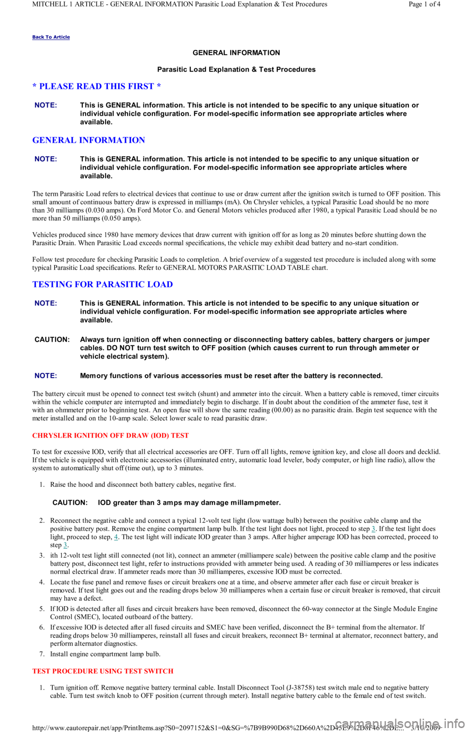
Back To Article
GENERAL INFORMATION
Parasitic Load Explanation & T est Procedures
* PLEASE READ THIS FIRST *
GENERAL INFORMATION
The term Parasitic Load refers to electrical devices that continue to use or draw current after the ignition switch is turned to OFF position. This
small amount of continuous battery draw is expressed in milliamps (mA). On Chrysler vehicles, a typical Parasitic Load should be no more
than 30 milliamps (0.030 amps). On Ford Motor Co. and General Motors vehicles produced after 1980, a typical Parasitic Load should be no
more than 50 milliamps (0.050 amps).
Vehicles produced since 1980 have memory devices that draw current with ignition off for as long as 20 minutes before shutting down the
Parasitic Drain. When Parasitic Load exceeds normal specifications, the vehicle may exhibit dead battery and no-start condition.
Follow test procedure for checking Parasitic Loads to completion. A brief overview of a suggested test procedure is included along with some
typical Parasitic Load specifications. Refer to GENERAL MOTORS PARASITIC LOAD TABLE chart.
TESTING FOR PARASITIC LOAD
The battery circuit must be opened to connect test switch (shunt) and ammeter into the circuit. When a battery cable is removed, timer circuits
within the vehicle computer are interrupted and immediately begin to discharge. If in doubt about the condition of the ammeter fuse, test it
with an ohmmeter prior to beginning test. An open fuse will show the same reading (00.00) as no parasitic drain. Begin test sequence with the
meter installed and on the 10-amp scale. Select lower scale to read parasitic draw.
CHRYSLER IGNITION OFF DRAW (IOD) TEST
To test for excessive IOD, verify that all electrical accessories are OFF. Turn off all lights, remove ignition key, and close all doors and decklid.
If the vehicle is equipped with electronic accessories (illuminated entry, automatic load leveler, body computer, or high line radio), allow the
system to automatically shut off (time out), up to 3 minutes.
1. Raise the hood and disconnect both battery cables, negative first.
2. Reconnect the negative cable and connect a typical 12-volt test light (low wattage bulb) between the positive cable clamp and the
positive battery post. Remove the engine compartment lamp bulb. If the test light does not light, proceed to step 3
. If the test light does
light, proceed to step, 4
. The test light will indicate IOD greater than 3 amps. After higher amperage IOD has been corrected, proceed to
step 3
.
3. ith 12-volt test light still connected (not lit), connect an ammeter (milliampere scale) between the positive cable clamp and the positive
battery post, disconnect test light, refer to instructions provided with ammeter being used. A reading of 30 milliamperes or less indicates
normal electrical draw. If ammeter reads more than 30 milliamperes, excessive IOD must be corrected.
4. Locate the fuse panel and remove fuses or circuit breakers one at a time, and observe ammeter after each fuse or circuit breaker is
removed. If test light goes out and the reading drops below 30 milliamperes when a certain fuse or circuit breaker is removed, that circuit
may have a defect.
5. If IOD is detected after all fuses and circuit breakers have been removed, disconnect the 60-way connector at the Single Module Engine
Control (SMEC), located outboard of the battery.
6. If excessive IOD is detected after all fused circuits and SMEC have been verified, disconnect the B+ terminal from the alternat o r. If
reading drops below 30 milliamperes, reinstall all fuses and circuit breakers, reconnect B+ terminal at alternator, reconnect battery, and
perform alternator diagnostics.
7. Install engine compartment lamp bulb.
TEST PROCEDURE USING TEST SWITCH
1. Turn ignition off. Remove negative battery terminal cable. Install Disconnect Tool (J-38758) test switch male end to negative battery
cable. Turn test switch knob to OFF position (current through meter). Install negative battery cable to the female end of test switch. NOTE:This is GENERAL inform ation. This article is not intended to be specific to any unique situation or
individual vehicle configuration. For m odel-specific inform ation see appropriate articles where
available.
NOTE:This is GENERAL inform ation. This article is not intended to be specific to any unique situation or
individual vehicle configuration. For m odel-specific inform ation see appropriate articles where
available.
NOTE:This is GENERAL inform ation. This article is not intended to be specific to any unique situation or
individual vehicle configuration. For m odel-specific inform ation see appropriate articles where
available.
CAUT ION: Always turn ignition off when connecting or disconnecting battery cables, battery chargers or jum per
cables. DO NOT turn test switch to OFF position (which causes current to run through am m eter or
vehicle electrical system ).
NOTE:Mem ory functions of various accessories m ust be reset after the battery is reconnected.
CAUT ION: IOD greater than 3 am ps m ay dam age m illam pm eter.
Page 1 of 4 MITCHELL 1 ARTICLE - GENERAL INFORMATION Parasitic Load Explanation & Test Procedures
3/10/2009 http://www.eautorepair.net/app/PrintItems.asp?S0=2097152&S1=0&SG=%7B9B990D68%2D660A%2D45E9%2D8F46%2DE
...
Page 415 of 454
inspect and repair circuit between switch harness connector and fuse panel.
5.Check Kickdown Switch
Turn ignition off. Check continuity between kickdown switch terminals. Continuity should only exist with accelerator fully depressed. I
f
switch is functioning correctly, go to next step. Replace switch if it failed testing. Road test vehicle to verify repair.
6.Check Circuit Between Kickdown Switch & Kickdown Solenoid
Ensure ignition is off. Disconnect kickdown switch harness connector. Disconnect kickdown solenoid harness connector. Check
continuity of White/Black wire between switch harness connector and solenoid harness connector. If continuity does not exist, inspect
and repair open circuit as needed. If continuity exists, check continuity between White/Black wire terminal at solenoid harness
connector and ground. If continuity exists, inspect and repair short circuit as needed. If continuity does not exist, replace kickdown
solenoid.
VACUUM THROTTLE VALVE DIAPHRAGM (MODULATOR) TEST
1.Check System Integrity
Inspect all vacuum hoses and connections for leaks or damage. Disconnect vacuum hose at diaphragm connection and inspect for
leaking ATF. Repair as needed. Go to next step.
2.Check Vacuum At Modulator
Ensure ignition is off. Disconnect vacuum hose at modulator valve and connect vacuum gauge to hose. Start and run engine at idle.
Vacuum should be 15-22 In. Hg. If vacuum is not within specification, inspect and repair vacuum hose. If vacuum is within specification,
go to next step.
3.Check Modulator Valve Function
Turn ignition off. Remove modulator valve from transaxle. Connect hand-held vacuum pump to valve. Apply 16-20 In. Hg of vacuum.
Ensure vacuum is held by valve. Release vacuum and verify that valve moves freely. If valve is functioning correctly, go to next step.
Replace valve if it fails testing.
4.Check Vacuum Diaphragm Rod
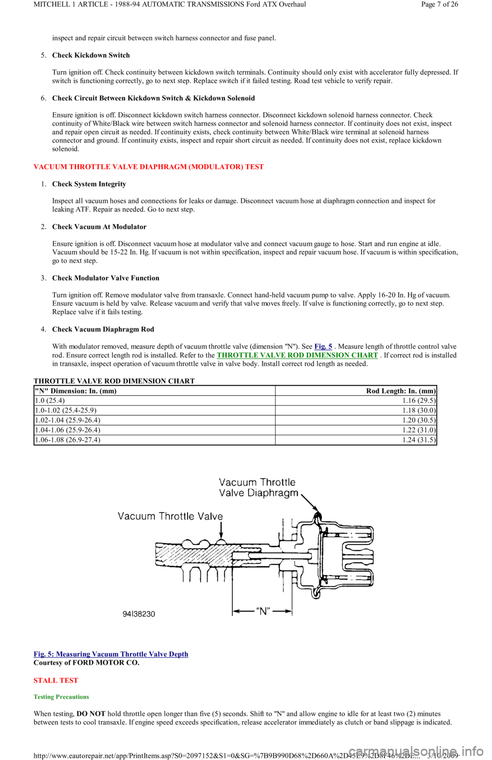
With modulator removed, measure depth of vacuum throttle valve (dimension "N"). See Fig. 5
. Measure length of throttle control valve
rod. Ensure correct length rod is installed. Refer to the THROTTLE VALVE ROD DIMENSION CHART
. If correct rod is installed
in transaxle, inspect operation of vacuum throttle valve in valve body. Install correct rod length as needed.
THROTTLE VALVE ROD DIMENSION CHART
Fig. 5: Measuring Vacuum Throttle Valve Depth
Courtesy of FORD MOTOR CO.
STALL TEST
Testing Precautions
When testing, DO NOT hold throttle open longer than five (5) seconds. Shift to "N" and allow engine to idle for at least two (2) minutes
between tests to cool transaxle. If engine speed exceeds specification, release accelerator immediately as clutch or band slippage is indicated.
"N" Dimension: In. (mm)Rod Length: In. (mm)
1.0 (25.4)1.16 (29.5)
1.0-1.02 (25.4-25.9)1.18 (30.0)
1.02-1.04 (25.9-26.4)1.20 (30.5)
1.04-1.06 (25.9-26.4)1.22 (31.0)
1.06-1.08 (26.9-27.4)1.24 (31.5)
Page 7 of 26 MITCHELL 1 ARTICLE - 1988-94 AUTOMATIC TRANSMISSIONS Ford ATX Overhaul
3/10/2009 http://www.eautorepair.net/app/PrintItems.asp?S0=2097152&S1=0&SG=%7B9B990D68%2D660A%2D45E9%2D8F46%2DE
...