1991 FORD FESTIVA open hood
[x] Cancel search: open hoodPage 277 of 454
Here we give you underhood views or schematics of vacuum-hose routing which can help you find incorrectly routed hoses. Remember, a
vacuum leak or incorrectly routed vacuum hose on computer-controlled vehicle can cause many driveability problems.
REMOVAL, OVERHAUL & INSTALLATION
After you've diagnosed the problem, this is where to go for the nuts-and-bolts of the job. Here you'll find procedures and specifications for
removing, overhauling (if available) and installing components.
WIRING DIAGRAMS - ENGINE PERFORMANCE
2002 & EARLIER
On 2002 and earlier models, once ENGINE PERFORMANCE is selected as the service category, the expanded menu will display a WIRING
DIAGRAMS - ENGINE PERFORMANCE heading. Once the wiring diagrams article is selected, select the engine performance wiring
diagrams for your lookup model.
2003 & LATER
On models newer than 2002, we have moved all wiring diagrams under a centralized first level model-specific lookup titled WIRING
DIAGRAMS-ALL. When selected, SYSTEM WIRING DIAGRAMS article will display in the center panel. This article contains all available
wiring diagrams related to the selected vehicle. These same wiring diagrams can also be found under the ELECTRICAL/WIRING DIAGRAMS
heading. NOTE:T his article is generic in nature and all inform ation does not apply to all vehicles. For vehicle specific
inform ation, see the appropriate articles in the ENGINE PERFORMANCE category.
NOTE:T his article is generic in nature and all inform ation does not apply to all vehicles. For vehicle specific
inform ation, see the appropriate articles in the ENGINE PERFORMANCE category.
NOTE:T his article is generic in nature and all inform ation does not apply to all vehicles. For vehicle specific
inform ation, see the appropriate articles in the ENGINE PERFORMANCE category.
NOTE:System Wiring diagram s for have been enhanced to include COLORS. T his will enable you to m ore
easily trace a circuit from its source to its destination, without losing your circuit due to parallel or
intersecting lines. Using these diagram s, you can easily identify and trace com ponent circuits, to help
locate shorts and opens in circuits. T hese diagram s can also help you understand how individual
circuits function within a system .
Copyr ight 2009 Mitchell Repair Information Company, LLC. All Rights Reserved.
Article GUID: A00002340
Page 3 of 3 MITCHELL 1 ARTICLE - GENERAL INFORMATION How To Use The Engine Performance Section - 1989 & Newer Models
3/10/2009 http://www.eautorepair.net/app/PrintItems.asp?S0=2097152&S1=0&SG=%7B9B990D68%2D660A%2D45E9%2D8F46%2DE
...
Page 278 of 454
Back To Article
GENERAL INFORMATION
Parasitic Load Explanation & T est Procedures
* PLEASE READ THIS FIRST *
GENERAL INFORMATION
The term Parasitic Load refers to electrical devices that continue to use or draw current after the ignition switch is turned to OFF position. This
small amount of continuous battery draw is expressed in milliamps (mA). On Chrysler vehicles, a typical Parasitic Load should be no more
than 30 milliamps (0.030 amps). On Ford Motor Co. and General Motors vehicles produced after 1980, a typical Parasitic Load should be no
more than 50 milliamps (0.050 amps).
Vehicles produced since 1980 have memory devices that draw current with ignition off for as long as 20 minutes before shutting down the
Parasitic Drain. When Parasitic Load exceeds normal specifications, the vehicle may exhibit dead battery and no-start condition.
Follow test procedure for checking Parasitic Loads to completion. A brief overview of a suggested test procedure is included along with some
typical Parasitic Load specifications. Refer to GENERAL MOTORS PARASITIC LOAD TABLE chart.
TESTING FOR PARASITIC LOAD
The battery circuit must be opened to connect test switch (shunt) and ammeter into the circuit. When a battery cable is removed, timer circuits
within the vehicle computer are interrupted and immediately begin to discharge. If in doubt about the condition of the ammeter fuse, test it
with an ohmmeter prior to beginning test. An open fuse will show the same reading (00.00) as no parasitic drain. Begin test sequence with the
meter installed and on the 10-amp scale. Select lower scale to read parasitic draw.
CHRYSLER IGNITION OFF DRAW (IOD) TEST
To test for excessive IOD, verify that all electrical accessories are OFF. Turn off all lights, remove ignition key, and close all doors and decklid.
If the vehicle is equipped with electronic accessories (illuminated entry, automatic load leveler, body computer, or high line radio), allow the
system to automatically shut off (time out), up to 3 minutes.
1. Raise the hood and disconnect both battery cables, negative first.
2. Reconnect the negative cable and connect a typical 12-volt test light (low wattage bulb) between the positive cable clamp and the
positive battery post. Remove the engine compartment lamp bulb. If the test light does not light, proceed to step 3
. If the test light does
light, proceed to step, 4
. The test light will indicate IOD greater than 3 amps. After higher amperage IOD has been corrected, proceed to
step 3
.
3. ith 12-volt test light still connected (not lit), connect an ammeter (milliampere scale) between the positive cable clamp and the positive
battery post, disconnect test light, refer to instructions provided with ammeter being used. A reading of 30 milliamperes or less indicates
normal electrical draw. If ammeter reads more than 30 milliamperes, excessive IOD must be corrected.
4. Locate the fuse panel and remove fuses or circuit breakers one at a time, and observe ammeter after each fuse or circuit breaker is
removed. If test light goes out and the reading drops below 30 milliamperes when a certain fuse or circuit breaker is removed, that circuit
may have a defect.
5. If IOD is detected after all fuses and circuit breakers have been removed, disconnect the 60-way connector at the Single Module Engine
Control (SMEC), located outboard of the battery.
6. If excessive IOD is detected after all fused circuits and SMEC have been verified, disconnect the B+ terminal from the alternat o r. If
reading drops below 30 milliamperes, reinstall all fuses and circuit breakers, reconnect B+ terminal at alternator, reconnect battery, and
perform alternator diagnostics.
7. Install engine compartment lamp bulb.
TEST PROCEDURE USING TEST SWITCH
1. Turn ignition off. Remove negative battery terminal cable. Install Disconnect Tool (J-38758) test switch male end to negative battery
cable. Turn test switch knob to OFF position (current through meter). Install negative battery cable to the female end of test switch. NOTE:This is GENERAL inform ation. This article is not intended to be specific to any unique situation or
individual vehicle configuration. For m odel-specific inform ation see appropriate articles where
available.
NOTE:This is GENERAL inform ation. This article is not intended to be specific to any unique situation or
individual vehicle configuration. For m odel-specific inform ation see appropriate articles where
available.
NOTE:This is GENERAL inform ation. This article is not intended to be specific to any unique situation or
individual vehicle configuration. For m odel-specific inform ation see appropriate articles where
available.
CAUT ION: Always turn ignition off when connecting or disconnecting battery cables, battery chargers or jum per
cables. DO NOT turn test switch to OFF position (which causes current to run through am m eter or
vehicle electrical system ).
NOTE:Mem ory functions of various accessories m ust be reset after the battery is reconnected.
CAUT ION: IOD greater than 3 am ps m ay dam age m illam pm eter.
Page 1 of 4 MITCHELL 1 ARTICLE - GENERAL INFORMATION Parasitic Load Explanation & Test Procedures
3/10/2009 http://www.eautorepair.net/app/PrintItems.asp?S0=2097152&S1=0&SG=%7B9B990D68%2D660A%2D45E9%2D8F46%2DE
...
Page 279 of 454
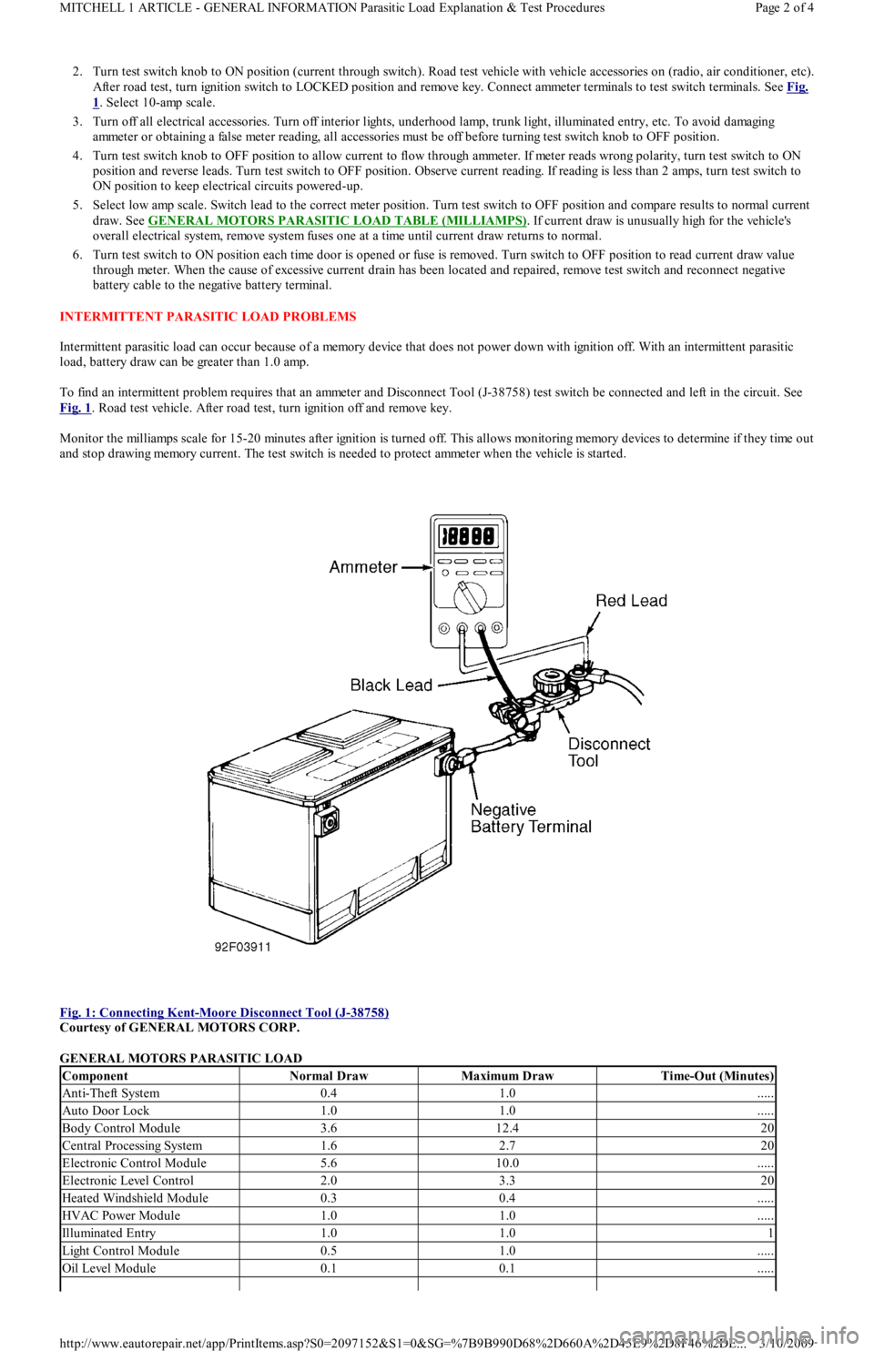
2. Turn test switch knob to ON position (current through switch). Road test vehicle with vehicle accessories on (radio, air conditioner, etc).
After road test, turn ignition switch to LOCKED position and remove key. Connect ammeter terminals to test switch terminals. See Fig.
1. Select 10-amp scale.
3. Turn off all electrical accessories. Turn off interior lights, underhood lamp, trunk light, illuminated entry, etc. To avoid damaging
ammeter or obtaining a false meter reading, all accessories must be off before turning test switch knob to OFF position.
4. Turn test switch knob to OFF position to allow current to flow through ammeter. If meter reads wrong polarity, turn test switch to ON
position and reverse leads. Turn test switch to OFF position. Observe current reading. If reading is less than 2 amps, turn test switch to
ON position to keep electrical circuits powered-up.
5. Select low amp scale. Switch lead to the correct meter position. Turn test switch to OFF position and compare results to normal current
draw. See GENERAL MOTORS PARASITIC LOAD TABLE (MILLIAMPS)
. If current draw is unusually high for the vehicle's
overall electrical system, remove system fuses one at a time until current draw returns to normal.
6. Turn test switch to ON position each time door is opened or fuse is removed. Turn switch to OFF position to read current draw va l u e
through meter. When the cause of excessive current drain has been located and repaired, remove test switch and reconnect negative
battery cable to the negative battery terminal.
INTERMITTENT PARASITIC LOAD PROBLEMS
Intermittent parasitic load can occur because of a memory device that does not power down with ignition off. With an intermittent parasitic
load, battery draw can be greater than 1.0 amp.
To find an intermittent problem requires that an ammeter and Disconnect Tool (J-38758) test switch be connected and left in the circuit. See
Fig. 1
. Road test vehicle. After road test, turn ignition off and remove key.
Monitor the milliamps scale for 15-20 minutes after ignition is turned off. This allows monitoring memory devices to determine if they time out
and stop drawing memory current. The test switch is needed to protect ammeter when the vehicle is started.
Fig. 1: Connecting Kent
-Moore Disconnect Tool (J-38758)
Courtesy of GENERAL MOTORS CORP.
GENERAL MOTORS PARASITIC LOAD
ComponentNormal DrawMaximum DrawTime-Out (Minutes)
Anti-Theft System0.41.0.....
Auto Door Lock1.01.0.....
Body Control Module3.612.420
Central Processing System1.62.720
Electronic Control Module5.610.0.....
Electronic Level Control2.03.320
Heated Windshield Module0.30.4.....
HVAC Power Module1.01.0.....
Illuminated Entry1.01.01
Light Control Module0.51.0.....
Oil Level Module0.10.1.....
Page 2 of 4 MITCHELL 1 ARTICLE - GENERAL INFORMATION Parasitic Load Explanation & Test Procedures
3/10/2009 http://www.eautorepair.net/app/PrintItems.asp?S0=2097152&S1=0&SG=%7B9B990D68%2D660A%2D45E9%2D8F46%2DE
...
Page 291 of 454
![FORD FESTIVA 1991 Service Manual
Fig. 7: Single Injector w/Excessive Current Flow
- Current Pattern
EXAMPLE #2 - VOLTAGE CONTROLLED DRIVER
This time we will look at a GM 3.1L V6 VIN [T]. Fig. Fig. 8
shows the 1, 3, 5 (odd) inje FORD FESTIVA 1991 Service Manual
Fig. 7: Single Injector w/Excessive Current Flow
- Current Pattern
EXAMPLE #2 - VOLTAGE CONTROLLED DRIVER
This time we will look at a GM 3.1L V6 VIN [T]. Fig. Fig. 8
shows the 1, 3, 5 (odd) inje](/manual-img/11/56935/w960_56935-290.png)
Fig. 7: Single Injector w/Excessive Current Flow
- Current Pattern
EXAMPLE #2 - VOLTAGE CONTROLLED DRIVER
This time we will look at a GM 3.1L V6 VIN [T]. Fig. Fig. 8
shows the 1, 3, 5 (odd) injector bank with the current waveform indicating about
a 2.6 amp draw at idle. This pattern, taken from a known good vehicle, correctly stays at or below the maximum 2.6 amps current range.
Ideally, the current for each bank should be very close in comparison.
Notice the small dimple on the current flow's rising edge. This is the actual injector opening or what engineers refer to as the "set p o in t . " Fo r
good idle quality, the set point should be uniform between the banks.
When discussing Ohm's Law as it pertains to this parallel circuit, consider that each injector has specified resistance of 12.2 ohms. Since all
three injectors are in parallel the total resistance of this parallel circuit drops to 4.1 ohms. Fourteen volts divided by four ohms would pull a
maximum of 3.4 amps on this bank of injectors. However, as we discussed in EXAMPLE #1
above, other factors knock this value down to
roughly the 2.6 amp neighborhood.
Now we are going to take a look at the even bank of injectors; injectors 2, 4, and 6. See Fig. 9. Notice this bank peaked at 1.7 amps at idle as
compared to the 2.6 amps peak of the odd bank (Fig. Fig. 8
). Current flow between even and odd injectors banks is not uniform, yet it is not
causing a driveability problem. That is because it is still under the maximum amperage we figured out earlier. But be aware this vehicle could
develop a problem if the amperage flow increases any more.
Checking the resistance of this even injector group with a DVOM yielded 6.2 ohms, while the odd injector group in the previous example read
4.1 ohms.
Fig. 8: Injector Odd Bank w/Normal Current Flow
- Current Pattern
Fig. 9: Injector Even Bank w/Normal Current Flow
- Current Pattern
EXAMPLE #3 - VOLTAGE CONTROLLED DRIVER
Example #3 is of a Ford 5.0L V8 SEFI. Fig. Fig. 10
shows a waveform of an individual injector at idle with the Lab Scope set on 200
Page 10 of 19 MITCHELL 1 ARTICLE - GENERAL INFORMATION Waveforms - Injector Pattern Tutorial
3/10/2009 http://www.eautorepair.net/app/PrintItems.asp?S0=2097152&S1=0&SG=%7B9B990D68%2D660A%2D45E9%2D8F46%2DE
...
Page 346 of 454
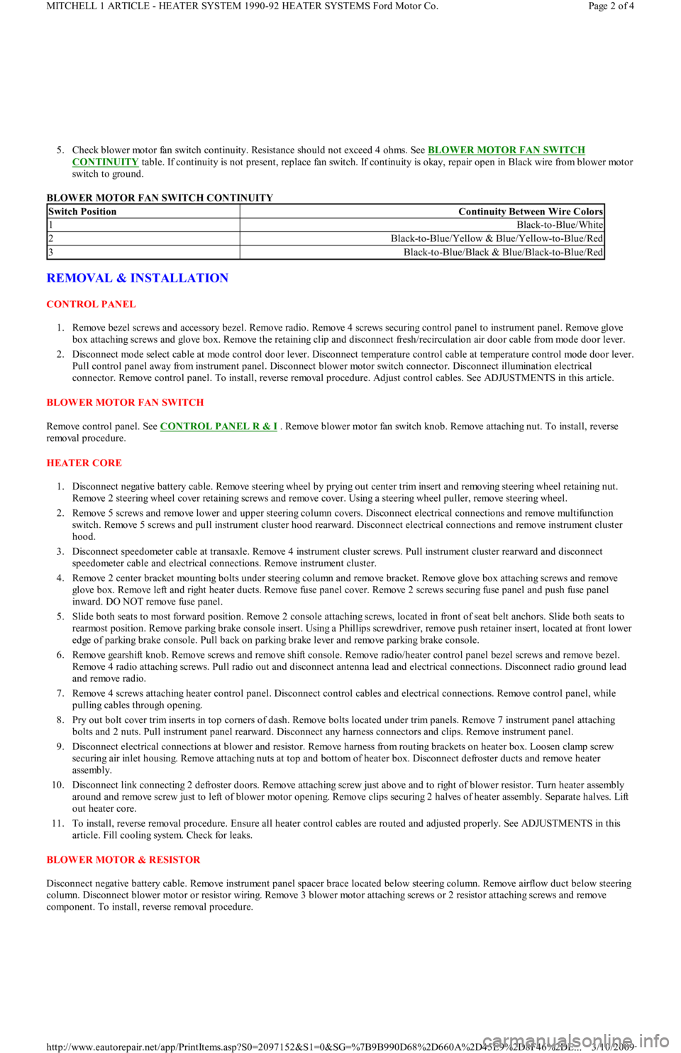
5. Check blower motor fan switch continuity. Resistance should not exceed 4 ohms. See BLOWER MOTOR FAN SWITCH
CONTINUITY table. If continuity is not present, replace fan switch. If continuity is okay, repair open in Black wire from blower motor
switch to ground.
BLOWER MOTOR FAN SWITCH CONTINUITY
REMOVAL & INSTALLATION
CONTROL PANEL
1. Remove bezel screws and accessory bezel. Remove radio. Remove 4 screws securing control panel to instrument panel. Remove glove
box attaching screws and glove box. Remove the retaining clip and disconnect fresh/recirculation air door cable from mode door lever.
2. Disconnect mode select cable at mode control door lever. Disconnect temperature control cable at temperature control mode door lever.
Pull control panel away from instrument panel. Disconnect blower motor switch connector. Disconnect illumination electrical
connector. Remove control panel. To install, reverse removal procedure. Adjust control cables. See ADJUSTMENTS in this article.
BLOWER MOTOR FAN SWITCH
Remove control panel. See CONTROL PANEL R & I
. Remove blower motor fan switch knob. Remove attaching nut. To install, reverse
removal procedure.
HEATER CORE
1. Disconnect negative battery cable. Remove steering wheel by prying out center trim insert and removing steering wheel retaining nut.
Remove 2 steering wheel cover retaining screws and remove cover. Using a steering wheel puller, remove steering wheel.
2. Remove 5 screws and remove lower and upper steering column covers. Disconnect electrical connections and remove multifunction
switch. Remove 5 screws and pull instrument cluster hood rearward. Disconnect electrical connections and remove instrument cluster
hood.
3. Disconnect speedometer cable at transaxle. Remove 4 instrument cluster screws. Pull instrument cluster rearward and disconnect
speedometer cable and electrical connections. Remove instrument cluster.
4. Remove 2 center bracket mounting bolts under steering column and remove bracket. Remove glove box attaching screws and remove
glove box. Remove left and right heater ducts. Remove fuse panel cover. Remove 2 screws securing fuse panel and push fuse panel
inward. DO NOT remove fuse panel.
5. Slide both seats to most forward position. Remove 2 console attaching screws, located in front of seat belt anchors. Slide both seats to
rearmost position. Remove parking brake console insert. Using a Phillips screwdriver, remove push retainer insert, located at front lower
edge of parking brake console. Pull back on parking brake lever and remove parking brake console.
6. Remove gearshift knob. Remove screws and remove shift console. Remove radio/heater control panel bezel screws and remove bezel.
Remove 4 radio attaching screws. Pull radio out and disconnect antenna lead and electrical connections. Disconnect radio ground lead
and remove radio.
7. Remove 4 screws attaching heater control panel. Disconnect control cables and electrical connections. Remove control panel, while
pulling cables through opening.
8. Pry out bolt cover trim inserts in top corners of dash. Remove bolts located under trim panels. Remove 7 instrument panel attaching
bolts and 2 nuts. Pull instrument panel rearward. Disconnect any harness connectors and clips. Remove instrument panel.
9. Disconnect electrical connections at blower and resistor. Remove harness from routing brackets on heater box. Loosen clamp screw
securing air inlet housing. Remove attaching nuts at top and bottom of heater box. Disconnect defroster ducts and remove heater
assembly.
10. Disconnect link connecting 2 defroster doors. Remove attaching screw just above and to right of blower resistor. Turn heater assembly
around and remove screw just to left of blower motor opening. Remove clips securing 2 halves of heater assembly. Separate halves. Lift
out heater core.
11. To install, reverse removal procedure. Ensure all heater control cables are routed and adjusted properly. See ADJUSTMENTS in this
article. Fill cooling system. Check for leaks.
BLOWER MOTOR & RESISTOR
Disconnect negative battery cable. Remove instrument panel spacer brace located below steering column. Remove airflow duct below steering
column. Disconnect blower motor or resistor wiring. Remove 3 blower motor attaching screws or 2 resistor attaching screws and remove
component. To install, reverse removal procedure.
Switch PositionContinuity Between Wire Colors
1Black-to-Blue/White
2Black-to-Blue/Yellow & Blue/Yellow-to-Blue/Red
3Black-to-Blue/Black & Blue/Black-to-Blue/Red
Page 2 of 4 MITCHELL 1 ARTICLE - HEATER SYSTEM 1990-92 HEATER SYSTEMS Ford Motor Co.
3/10/2009 http://www.eautorepair.net/app/PrintItems.asp?S0=2097152&S1=0&SG=%7B9B990D68%2D660A%2D45E9%2D8F46%2DE
...
Page 360 of 454
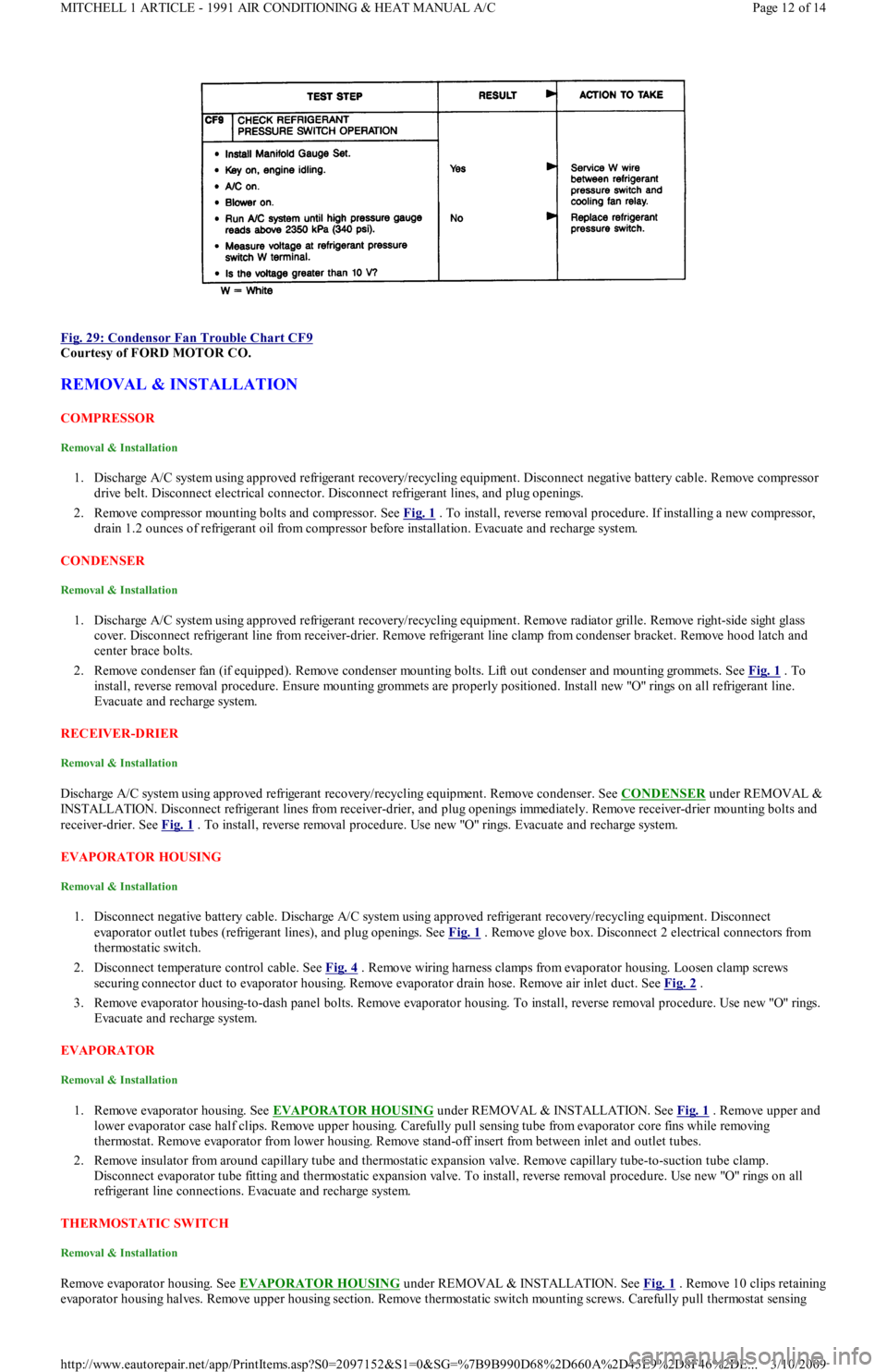
Fig. 29: Condensor Fan Trouble Chart CF9
Courtesy of FORD MOTOR CO.
REMOVAL & INSTALLATION
COMPRESSOR
Removal & Installation
1. Discharge A/C system using approved refrigerant recovery/recycling equipment. Disconnect negative battery cable. Remove compressor
drive belt. Disconnect electrical connector. Disconnect refrigerant lines, and plug openings.
2. Remove compressor mounting bolts and compressor. See Fig. 1
. To install, reverse removal procedure. If installing a new compressor,
drain 1.2 ounces of refrigerant oil from compressor before installation. Evacuate and recharge system.
CONDENSER
Removal & Installation
1. Discharge A/C system using approved refrigerant recovery/recycling equipment. Remove radiator grille. Remove right-side sight glass
cover. Disconnect refrigerant line from receiver-drier. Remove refrigerant line clamp from condenser bracket. Remove hood latch and
center brace bolts.
2. Remove condenser fan (if equipped). Remove condenser mounting bolts. Lift out condenser and mounting grommets. See Fig. 1
. To
install, reverse removal procedure. Ensure mounting grommets are properly positioned. Install new "O" rings on all refrigerant line.
Evacuate and recharge system.
RECEIVER-DRIER
Removal & Installation
Discharge A/C system using approved refrigerant recovery/recycling equipment. Remove condenser. See CONDENSER under REMOVAL &
INSTALLATION. Disconnect refrigerant lines from receiver-drier, and plug openings immediately. Remove receiver-drier mounting bolts and
receiver-drier. See Fig. 1
. To install, reverse removal procedure. Use new "O" rings. Evacuate and recharge system.
EVAPORATOR HOUSING
Removal & Installation
1. Disconnect negative battery cable. Discharge A/C system using approved refrigerant recovery/recycling equipment. Disconnect
evaporator outlet tubes (refrigerant lines), and plug openings. See Fig. 1
. Remove glove box. Disconnect 2 electrical connectors from
thermostatic switch.
2. Disconnect temperature control cable. See Fig. 4
. Remove wiring harness clamps from evaporator housing. Loosen clamp screws
securing connector duct to evaporator housing. Remove evaporator drain hose. Remove air inlet duct. See Fig. 2
.
3. Remove evaporator housing-to-dash panel bolts. Remove evaporator housing. To install, reverse removal procedure. Use new "O" rings.
Evacuate and recharge system.
EVAPORATOR
Removal & Installation
1. Remove evaporator housing. See EVAPORATOR HOUSING under REMOVAL & INSTALLATION. See Fig. 1 . Remove upper and
lower evaporator case half clips. Remove upper housing. Carefully pull sensing tube from evaporator core fins while removing
thermostat. Remove evaporator from lower housing. Remove stand-off insert from between inlet and outlet tubes.
2. Remove insulator from around capillary tube and thermostatic expansion valve. Remove capillary tube-to-suction tube clamp.
Disconnect evaporator tube fitting and thermostatic expansion valve. To install, reverse removal procedure. Use new "O" rings on all
refrigerant line connections. Evacuate and recharge system.
THERMOSTATIC SW ITCH
Removal & Installation
Remove evaporator housing. See EVAPORATOR HOUSING under REMOVAL & INSTALLATION. See Fig. 1. Remove 10 clips retaining
evaporator housing halves. Remove upper housing section. Remove thermostatic switch mounting screws. Carefully pull thermostat sensing
Page 12 of 14 MITCHELL 1 ARTICLE - 1991 AIR CONDITIONING & HEAT MANUAL A/C
3/10/2009 http://www.eautorepair.net/app/PrintItems.asp?S0=2097152&S1=0&SG=%7B9B990D68%2D660A%2D45E9%2D8F46%2DE
...
Page 361 of 454
tube from evaporator core fins while removing thermostatic switch. To install, reverse removal procedure. Evacuate and recharge system.
THERMOSTATIC EXPANSION VALVE
Removal & Installation
1. Discharge A/C system using approved refrigerant recovery/recycling equipment. Remove evaporator housing. See EVAPORATOR
HOUSING under REMOVAL & INSTALLATION. Remove air inlet duct. See Fig. 1 .
2. Remove insulation from sensing bulb. Disconnect thermostatic expansion valve at evaporator tube fitting and inlet tube fitting (from
receiver-drier). See Fig. 3
. Remove thermostatic expansion valve. To install, reverse removal procedure. Use new "O" rings. Evacuate
and recharge system.
A/C RELAYS
Removal & Installation
A/C relays are located in left front corner of engine compartment, near battery. Unclip relay holder from its mounting bracket. Disconnect
relay wiring. DO NOT pull on wiring connector to remove relay from holder. Remove relay from holder. To install, reverse removal procedure.
A/C-HEATER CONTROL ASSEMBLY
Removal & Installation
1. A/C control module is located above radio. Remove accessory bezel. Remove radio (if necessary) and glove box. Disconnect
recirculated/fresh air cable from door lever. See Fig. 5
. Disconnect mode select cable from door lever. See Fig. 6 .
2. Disconnect temperature control cable from door lever. See Fig. 4
. Pull control assembly away from dash, and disconnect wiring
connectors. Remove control assembly.
3. To install, reverse removal procedure. Check and adjust temperature control, recirculated/fresh air and mode cables. See
ADJUSTMENTS. Test control assembly operation.
BLOWER MOTOR
Removal & Installation
Disconnect negative battery cable. Remove A/C air outlet duct located below steering column. See Fig. 2 . Disconnect blower motor wiring.
Remove blower motor attaching screws and blower motor. Remove blower wheel attaching nut. Remove blower wheel and washer. To install,
reverse removal procedure.
BLOWER MOTOR RESISTOR
Removal & Installation
Disconnect negative battery cable. Remove air duct located below steering column. See Fig. 2 . Disconnect blower motor resistor wiring.
Remove blower resistor attaching screws and resistor. To install, reverse removal procedure.
AIR DISTRIBUTION PLENUM
Removal & Installation
1. Remove instrument panel. See INSTRUMENT PANEL under REMOVAL & INSTALLATION. Drain cooling system. Disconnect
heater hoses in engine compartment. Disconnect wiring for blower motor and blower resistor. Disengage wiring harness and antenna
lead from bracket on front of air distribution housing.
2. Loosen connector duct-to-air inlet clamp screw. Remove upper and lower mounting nuts from plenum. Disengage and remove plenum
from defroster ducts. To install, reverse removal procedure. Refill cooling system, and check for leaks.
HEATER CORE
Removal & Installation
1. Remove air distribution plenum. See AIR DISTRIBUTION PLENUM under REMOVAL & INSTALLATION. Disconnect linkage
connecting defroster doors. Remove attaching screw located near blower resistor. Turn housing around and remove attaching screw
located near blower motor opening.
2. Remove clips retaining blower housing halves. Separate blower housing halves. Remove heater core. Remove tube insert from heater
core. To install, reverse removal procedure. Test system for proper operation.
INSTRUMENT PANEL
Removal & Installation
1. Disconnect negative battery cable. Remove steering wheel, steering column covers and multifunction switch assembly. Disconnect
electrical connectors from switches on instrument panel. Remove instrument cluster hood.
2. Disconnect speedometer cable from transmission. Remove 4 instrument cluster screws. Pull instrument cluster out from instrument
panel cluster enough to disconnect wiring and speedometer cable. Remove instrument cluster.
3. Remove steering column shield. Remove shield bracket. Remove glove box. Remove fuse panel cover and 4 fuse panel screws. Pull fu se
panel out, but DO NOT remove. Remove shift lever console and mount brackets. CAUTION: DO NOT rem ove screw in front of blower resistor, or blower resistor m ounting plate will fall into air
distribution plenum . T o retrieve plate, disassem ble instrum ent panel.
Page 13 of 14 MITCHELL 1 ARTICLE - 1991 AIR CONDITIONING & HEAT MANUAL A/C
3/10/2009 http://www.eautorepair.net/app/PrintItems.asp?S0=2097152&S1=0&SG=%7B9B990D68%2D660A%2D45E9%2D8F46%2DE
...