1991 FORD FESTIVA oil capacities
[x] Cancel search: oil capacitiesPage 102 of 454

levels to proper level.
Removal (1.6L & 1.6L Turbo)
1. Relieve fuel pressure and discharge air conditioning system (if equipped). See FUEL PRESSURE RELEASE under REMOVAL &
INSTALLATION. Disconnect and remove battery, battery tray and battery tray support bracket.
2. Release wiring harness retaining straps from battery support tray. Disconnect windshield washer supply hose between fluid reservoir and
hood. Mark hinge locations and remove hood.
3. Disconnect intake air tube and wiring to ignition coil and vane airflow meter. Remove air cleaner/vane airflow meter assembly. Remove
air cleaner assembly support brackets. Disconnect intercooler hoses from turbocharger (if equipped).
4. Drain engine coolant and remove radiator. Disconnect accelerator cable, and remove retaining bracket from cam cover. Position cable to
one side.
5. Disconnect and plug fuel lines at fuel filter and pressure regulator. Disconnect power brake booster manifold vacuum hose from
manifold. Disconnect heater hoses at heater core tubes. Label and remove vacuum hoses located at throttle body.
6. For manual transaxle turbocharged vehicles, disconnect clutch cable and remove support bracket and cable from transmission. On non-
turbo vehicles, disconnect clutch slave hydraulic line. For automatic transaxle, remove transaxle cooler lines.
7. Disconnect starter wiring at starter. Remove harness from locating strap on bracket. Disconnect alternator wiring. Disconnect wiring
from engine coolant sensors located on rear of engine block. Remove ground connection at bracket on thermostat cover. Disconnect O2
sensor wire, main wiring harness connector, TPS connector (turbocharged only), knock sensor connector, distributor wiring and
transaxle wiring. Disconnect ground wire and strap at front of engine, and reinstall lifting eye.
8. Remove engine oil dipstick and retaining clip. Remove power steering pump from mounting bracket. Remove power steering pump
mounting bracket. With hoses attached, position pump aside. Remove upper air conditioning compressor retaining bolts (if equipped).
9. Raise vehicle on hoist. Drain engine oil and cooling system. On vehicles with air conditioning, remove lower air conditioning
compressor mounting bolts, and position compressor out of way.
10. Remove front wheels and tires. Remove front ball joints-to-ste e r in g kn u c kl e s r e t a in in g b o l t s. R e mo ve sp l a sh gu a r d s. Dr a in t ransmission
oil and remove half shafts from differential. Remove front exhaust pipe bracket located on lower side of engine. Disconnect front
exhaust pipe from exhaust manifold, or turbocharger (if equipped).
11. Remove frame support bar-to-engine support bolt. Loosen right control arm bolt and, pivot support bar downward. Disengage rubber
exhaust hangers located directly behind catalytic converter. Allow exhaust system to hang down 6 inches, and support system with
mechanic's wire. Unbolt shift linkage and stabilizer bar at transaxle. Remove nuts from front and rear engine mounts, and lower vehicle.
12. Attach chains onto lift eyes at ends of cylinder head, and support engine with hoist. Remove RH engine mount through bolt. Raise
engine off mounts and slightly pivot engine/transaxle assembly. Disconnect oil pressure sensor and route starter/alternator wiring
harness from engine. Carefully lift engine/transaxle assembly, turn assembly while raising to clear brake master cylinder, shift linkage
universal joint, radiator support and air conditioning lines (if equipped).
13. Remove intake manifold support bracket. Remove gusset plate(s) (if equipped). Remove starter. Remove transaxle-to-engine retaining
bolts. Identify bolts to ensure correct installation. Separate transaxle from engine. On manual transaxle, remove pressure plate, clutch
disc and flywheel. On automatic transaxle, remove flexplate.
Installation (1.6L & 1.6L Turbo)
1. Install transaxle to engine in reverse order of removal. Attach hoist to engine/transaxle assembly and position assembly in vehicle.
Before engine contacts mounts, route starter, alternator and oil pressure sensor wiring, and connect oil pressure sensor. Lower engine
until front mount seats on crossmember. Install through bolt on RH engine mount. DO NOT tighten bolt.
2. Remove hoist. Raise vehicle and support with jackstands. Align rear engine mount to crossmember, and install retaining nuts to front
and rear engine mounts. Tighten nuts to specification. See TORQUE SPECIFICATIONS
table at end of article.
3. On manual transaxles, connect shift coupling and stabilizer. Tighten to specification. On automatic transaxles, connect shift linkage and
oil cooler lines. Tighten linkage retaining bolt, shift cable pivot and oil cooler hose clamps to specification. Connect front exhaust pipe
to manifold (or turbocharger). Install exhaust pipe to support bracket. Tighten bolts to specification. Tighten manifold (or turbocharger)
to specification. Attach rubber exhaust hangers. Position cross brace. Tighten retaining nut and bolt and right control arm front bolt.
4. Install drive axles. Install ball joint retaining bolts and tighten to specification. Mount A/C Compressor to engine (if equipped). Tighten
lower retaining bolts to specification. Install splash guards. Install tire and wheel assemblies. Tighten retaining nuts to specification.
5. Lower vehicle. Install upper A/C compressor retaining bolts (if equipped). Tighten bolts to specification. Tighten RH engine mo u n t
through bolt to specification. Connect alternator wiring.
6. Position power steering pump bracket on stud. Lower pump into engine compartment. Install power steering pump bracket retaining
bolts and nut. Tighten to specification. Install power steering pump and belt. Tighten adjustment nut and pivot bolt to specification.
7. Install engine oil dipstick and retaining clip. Install ground strap and ground wire to cylinder head. Install clutch cable (if equipped).
Connect clutch hydraulic line if equipped with manual transaxle or naturally aspirated. Connect transmission electrical connectors.
Connect fuel lines to fuel filter and pressure regulator. Install intake air tube to throttle body.
8. Install intercooler hoses on turbocharged models. Install air cleaner assembly brackets. Install air cleaner assembly with airflow meter
attached. Install intake air tube. Install coil and airflow meter connectors. Connect coolant crankcase and air bypass hoses. Install
vacuum hoses as noted in disassembly.
9. Connect accelerator cable. Install retaining bracket. Install power brake booster hose. Remove speedometer cable from transaxle. Fill
transaxle to specification. See CAPACITIES in SERVICE & ADJUSTMENT SPECIFICATIONS article. Install speedometer cable.
Connect speedometer cable connector. Fill engine oil to capacity.
10. Install radiator/fan assembly. Tighten bracket retaining bolts to specification. Connect coolant hoses and fan electrical connector. Fill
coolant to specification.
11. Install hood and connect washer hose. Install battery tray support, battery tray, battery and battery hold-down. Connect battery
terminal. Evacuate and charge air conditioning system (if equipped). Road test vehicle and inspect for leaks.
INTAKE MANIFOLD
Removal (1.3L)
CAUT ION: DO NOT allow com pressor to hang by hoses. T ie up com pressor with m echanic's wire.
Page 2 of 19 MITCHELL 1 ARTICLE - ENGINE OVERHAUL 1991-92 FORD MOTOR CO. ENGINES 1.3L & 1.6L 4-Cylinder
3/10/2009 http://www.eautorepair.net/app/PrintItems.asp?S0=2097152&S1=0&SG=%7B959286D2%2D3A85%2D4BFC%2D9C5C%2D
...
Page 153 of 454
Back To Article
C - SPECIFICATIONS
1991 ENGINE PERFORMANCE Ford/Mercury - Service & Adjustm ent Specifications
INTRODUCTION
Use this article to quickly find specifications related to servicing and on-vehicle adjustments. This is a quick-reference article to use when you
are familiar with an adjustment procedure and only need a specification.
CAPACITIES
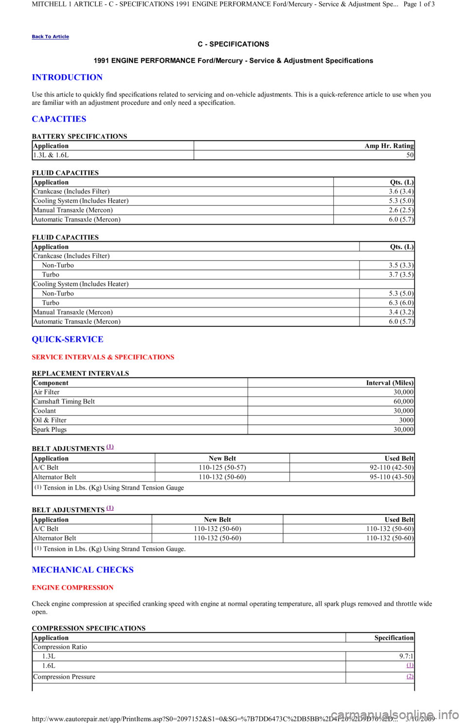
BATTERY SPECIFICATIONS
FLUID CAPACITIES
FLUID CAPACITIES
QUICK-SERVICE
SERVICE INTERVALS & SPECIFICATIONS
REPLACEMENT INTERVALS
BELT ADJUSTMENTS
(1)
BELT ADJUSTMENTS
(1)
MECHANICAL CHECKS
ENGINE COMPRESSION
Check engine compression at specified cranking speed with engine at normal operating temperature, all spark plugs removed and throttle wide
open.
COMPRESSION SPECIFICATIONS
ApplicationAmp Hr. Rating
1.3L & 1.6L50
ApplicationQts. (L)
Crankcase (Includes Filter)3.6 (3.4)
Cooling System (Includes Heater)5.3 (5.0)
Manual Transaxle (Mercon)2.6 (2.5)
Automatic Transaxle (Mercon)6.0 (5.7)
ApplicationQts. (L)
Crankcase (Includes Filter)
Non-Turbo3.5 (3.3)
Turbo3.7 (3.5)
Cooling System (Includes Heater)
Non-Turbo5.3 (5.0)
Turbo6.3 (6.0)
Manual Transaxle (Mercon)3.4 (3.2)
Automatic Transaxle (Mercon)6.0 (5.7)
ComponentInterval (Miles)
Air Filter30,000
Camsh aft Timin g Bel t60,000
Coolant30,000
Oil & Filter3000
Spark Plugs30,000
ApplicationNew BeltUsed Belt
A/C Belt110-125 (50-57)92-110 (42-50)
Alternator Belt110-132 (50-60)95-110 (43-50)
(1)Tension in Lbs. (Kg) Using Strand Tension Gauge
ApplicationNew BeltUsed Belt
A/C Belt110-132 (50-60)110-132 (50-60)
Alternator Belt110-132 (50-60)110-132 (50-60)
(1)Tension in Lbs. (Kg) Using Strand Tension Gauge.
ApplicationSpecification
Compression Ratio
1.3L9.7:1
1.6L(1)
Compression Pressure(2)
Page 1 of 3 MITCHELL 1 ARTICLE - C - SPECIFICATIONS 1991 ENGINE PERFORMANCE Ford/Mercury - Service & Adjustment Spe
...
3/10/2009 http://www.eautorepair.net/app/PrintItems.asp?S0=2097152&S1=0&SG=%7B7DD6473C%2DB5BB%2D4F20%2D9D70%2D
...
Page 306 of 454
Back To Article
1991 GENERAL SERVICING
A/C Com pressor Refrigerant Oil Checking
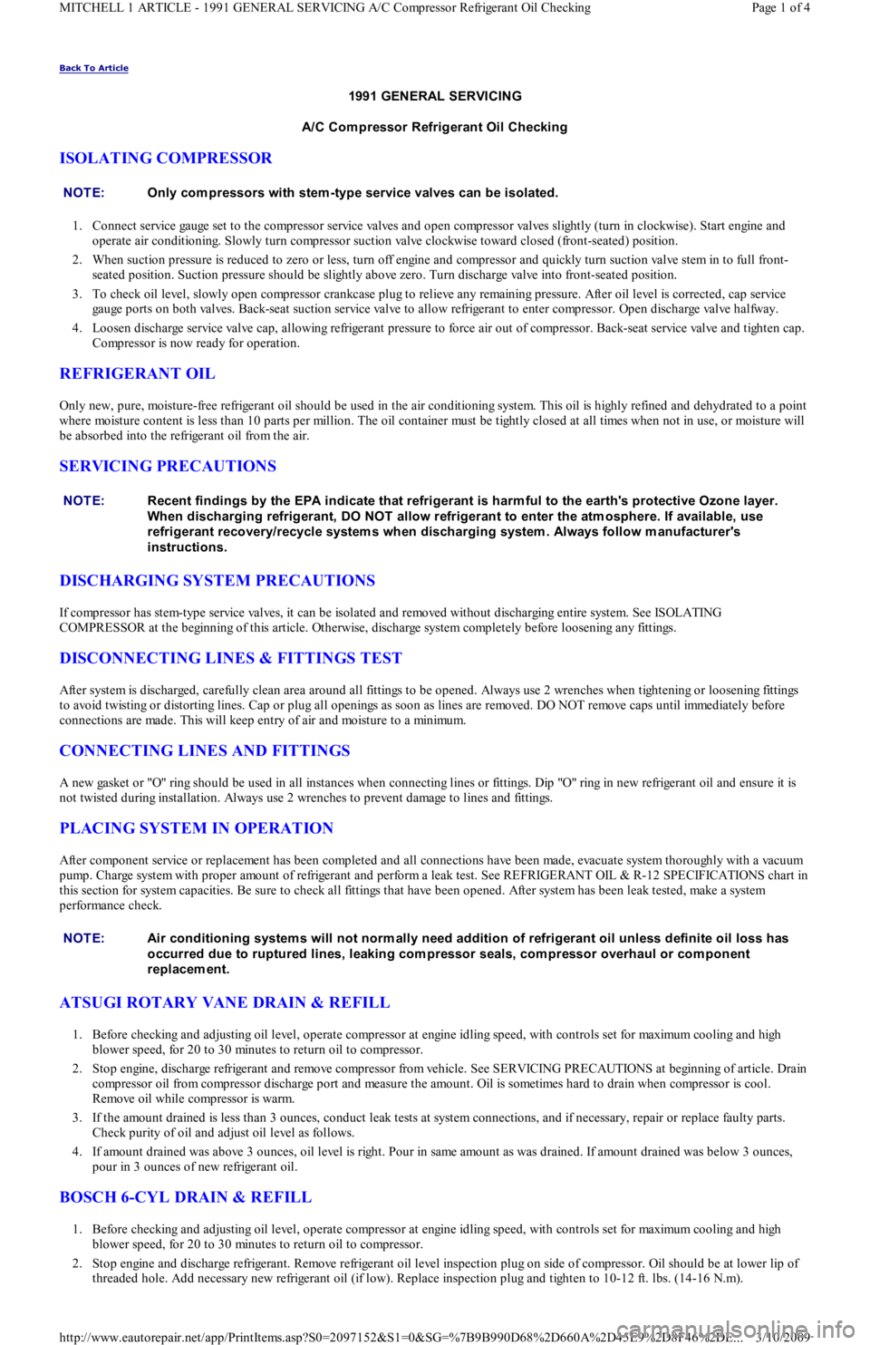
ISOLATING COMPRESSOR
1. Connect service gauge set to the compressor service valves and open compressor valves slightly (turn in clockwise). Start engine and
operate air conditioning. Slowly turn compressor suction valve clockwise toward closed (front-seated) position.
2. When suction pressure is reduced to zero or less, turn off engine and compressor and quickly turn suction valve stem in to full front-
seated position. Suction pressure should be slightly above zero. Turn discharge valve into front-seated position.
3. To check oil level, slowly open compressor crankcase plug to relieve any remaining pressure. After oil level is corrected, cap service
gauge ports on both valves. Back-seat suction service valve to allow refrigerant to enter compressor. Open discharge valve halfway.
4. Loosen discharge service valve cap, allowing refrigerant pressure to force air out of compressor. Back-seat service valve and tighten cap.
Compressor is now ready for operation.
REFRIGERANT OIL
Only new, pure, moisture-free refrigerant oil should be used in the air conditioning system. This oil is highly refined and dehydrated to a point
where moisture content is less than 10 parts per million. The oil container must be tightly closed at all times when not in use, or moisture will
be absorbed into the refrigerant oil from the air.
SERVICING PRECAUTIONS
DISCHARGING SYSTEM PRECAUTIONS
If compressor has stem-type service valves, it can be isolated and removed without discharging entire system. See ISOLATING
COMPRESSOR at the beginning of this article. Otherwise, discharge system completely before loosening any fittings.
DISCONNECTING LINES & FITTINGS TEST
After system is discharged, carefully clean area around all fittings to be opened. Always use 2 wrenches when tightening or loosening fittings
to avoid twisting or distorting lines. Cap or plug all openings as soon as lines are removed. DO NOT remove caps until immediately before
connections are made. This will keep entry of air and moisture to a minimum.
CONNECTING LINES AND FITTINGS
A new gasket or "O" ring should be used in all instances when connecting lines or fittings. Dip "O" ring in new refrigerant oil and ensure it is
not twisted during installation. Always use 2 wrenches to prevent damage to lines and fittings.
PLACING SYSTEM IN OPERATION
After component service or replacement has been completed and all connections have been made, evacuate system thoroughly with a vacuum
pump. Charge system with proper amount of refrigerant and perform a leak test. See REFRIGERANT OIL & R-12 SPECIFICATIONS chart in
this section for system capacities. Be sure to check all fittings that have been opened. After system has been leak tested, make a system
performance check.
ATSUGI ROTARY VANE DRAIN & REFILL
1. Before checking and adjusting oil level, operate compressor at engine idling speed, with controls set for maximum cooling and high
blower speed, for 20 to 30 minutes to return oil to compressor.
2. Stop engine, discharge refrigerant and remove compressor from vehicle. See SERVICING PRECAUTIONS at beginning of article. Drain
compressor oil from compressor discharge port and measure the amount. Oil is sometimes hard to drain when compressor is cool.
Remove oil while compressor is warm.
3. If the amount drained is less than 3 ounces, conduct leak tests at system connections, and if necessary, repair or replace faulty parts.
Check purity of oil and adjust oil level as follows.
4. If amount drained was above 3 ounces, oil level is right. Pour in same amount as was drained. If amount drained was below 3 ounces,
pour in 3 ounces of new refrigerant oil.
BOSCH 6-CYL DRAIN & REFILL
1. Before checking and adjusting oil level, operate compressor at engine idling speed, with controls set for maximum cooling and high
blower speed, for 20 to 30 minutes to return oil to compressor.
2. Stop engine and discharge refrigerant. Remove refrigerant oil level inspection plug on side of compressor. Oil should be at lower lip of
threaded hole. Add necessary new refrigerant oil (if low). Replace inspection plug and tighten to 10-12 ft. lbs. (14-16 N.m). NOTE:Only com pressors with stem -type service valves can be isolated.
NOTE:Recent findings by the EPA indicate that refrigerant is harm ful to the earth's protective Ozone layer.
When discharging refrigerant, DO NOT allow refrigerant to enter the atm osphere. If available, use
refrigerant recovery/recycle system s when discharging system . Always follow m anufacturer's
instructions.
NOTE:Air conditioning system s will not norm ally need addition of refrigerant oil unless definite oil loss has
occurred due to ruptured lines, leaking com pressor seals, com pressor overhaul or com ponent
replacem ent.
Page 1 of 4 MITCHELL 1 ARTICLE - 1991 GENERAL SERVICING A/C Compressor Refrigerant Oil Checking
3/10/2009 http://www.eautorepair.net/app/PrintItems.asp?S0=2097152&S1=0&SG=%7B9B990D68%2D660A%2D45E9%2D8F46%2DE
...
Page 317 of 454
Back To Article
A/C COMPRESSOR SERVICING
1991 GENERAL SERVICING Com pressor Service
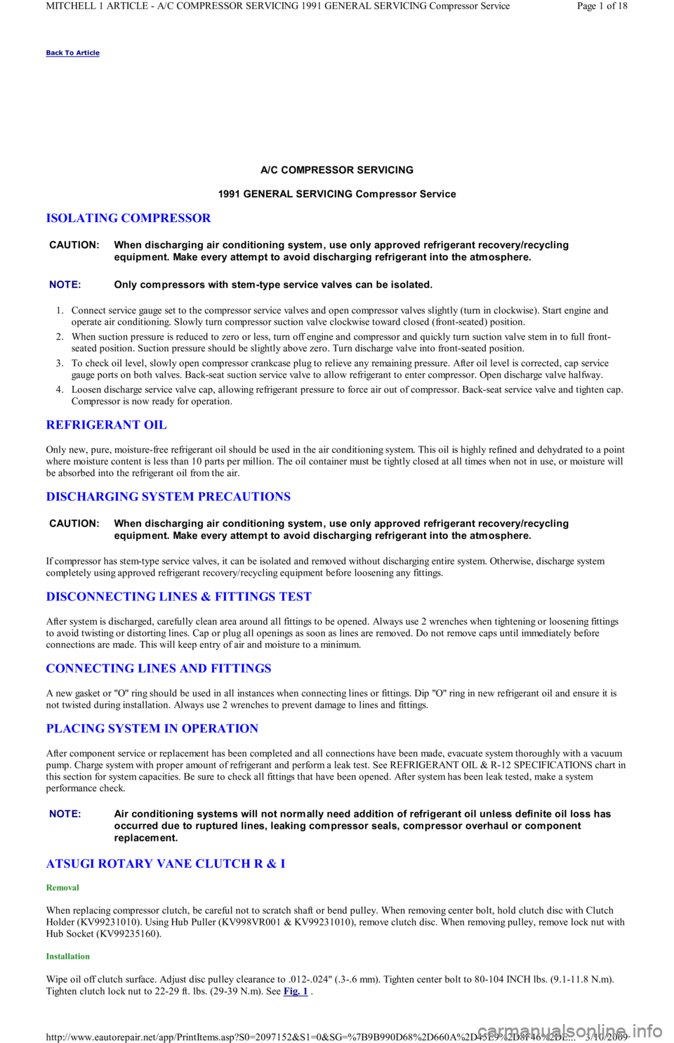
ISOLATING COMPRESSOR
1. Connect service gauge set to the compressor service valves and open compressor valves slightly (turn in clockwise). Start engine and
operate air conditioning. Slowly turn compressor suction valve clockwise toward closed (front-seated) position.
2. When suction pressure is reduced to zero or less, turn off engine and compressor and quickly turn suction valve stem in to full front-
seated position. Suction pressure should be slightly above zero. Turn discharge valve into front-seated position.
3. To check oil level, slowly open compressor crankcase plug to relieve any remaining pressure. After oil level is corrected, cap service
gauge ports on both valves. Back-seat suction service valve to allow refrigerant to enter compressor. Open discharge valve halfway.
4. Loosen discharge service valve cap, allowing refrigerant pressure to force air out of compressor. Back-seat service valve and tighten cap.
Compressor is now ready for operation.
REFRIGERANT OIL
Only new, pure, moisture-free refrigerant oil should be used in the air conditioning system. This oil is highly refined and dehydrated to a point
where moisture content is less than 10 parts per million. The oil container must be tightly closed at all times when not in use, or moisture will
be absorbed into the refrigerant oil from the air.
DISCHARGING SYSTEM PRECAUTIONS
If compressor has stem-type service valves, it can be isolated and removed without discharging entire system. Otherwise, discharge system
completely using approved refrigerant recovery/recycling equipment before loosening any fittings.
DISCONNECTING LINES & FITTINGS TEST
After system is discharged, carefully clean area around all fittings to be opened. Always use 2 wrenches when tightening or loosening fittings
to avoid twisting or distorting lines. Cap or plug all openings as soon as lines are removed. Do not remove caps until immediately before
connections are made. This will keep entry of air and moisture to a minimum.
CONNECTING LINES AND FITTINGS
A new gasket or "O" ring should be used in all instances when connecting lines or fittings. Dip "O" ring in new refrigerant oil and ensure it is
not twisted during installation. Always use 2 wrenches to prevent damage to lines and fittings.
PLACING SYSTEM IN OPERATION
After component service or replacement has been completed and all connections have been made, evacuate system thoroughly with a vacuum
pump. Charge system with proper amount of refrigerant and perform a leak test. See REFRIGERANT OIL & R-12 SPECIFICATIONS chart in
this section for system capacities. Be sure to check all fittings that have been opened. After system has been leak tested, make a system
performance check.
ATSUGI ROTARY VANE CLUTCH R & I
Removal
When replacing compressor clutch, be careful not to scratch shaft or bend pulley. When removing center bolt, hold clutch disc with Clutch
Holder (KV99231010). Using Hub Puller (KV998VR001 & KV99231010), remove clutch disc. When removing pulley, remove lock nut with
Hub Socket (KV99235160).
Installation
Wipe oil off clutch surface. Adjust disc pulley clearance to .012-.024" (.3-.6 mm). Tighten center bolt to 80-104 INCH lbs. (9.1-11.8 N.m).
Tighten clutch lock nut to 22-29 ft. lbs. (29-39 N.m). See Fig. 1
. CAUT ION: When discharging air conditioning system , use only approved refrigerant recovery/recycling
equipm ent. Make every attem pt to avoid discharging refrigerant into the atm osphere.
NOTE:Only com pressors with stem -type service valves can be isolated.
CAUT ION: When discharging air conditioning system , use only approved refrigerant recovery/recycling
equipm ent. Make every attem pt to avoid discharging refrigerant into the atm osphere.
NOTE:Air conditioning system s will not norm ally need addition of refrigerant oil unless definite oil loss has
occurred due to ruptured lines, leaking com pressor seals, com pressor overhaul or com ponent
replacem ent.
Page 1 of 18 MITCHELL 1 ARTICLE - A/C COMPRESSOR SERVICING 1991 GENERAL SERVICING Compressor Service
3/10/2009 http://www.eautorepair.net/app/PrintItems.asp?S0=2097152&S1=0&SG=%7B9B990D68%2D660A%2D45E9%2D8F46%2DE
...
Page 327 of 454
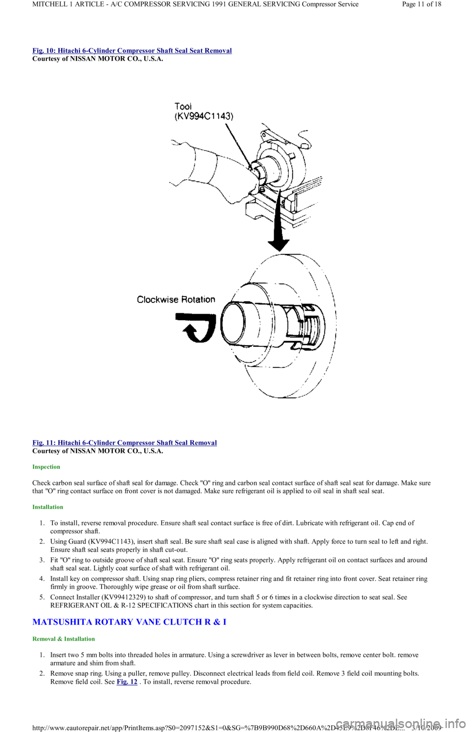
Fig. 10: Hitachi 6-Cylinder Compressor Shaft Seal Seat Removal
Courtesy of NISSAN MOTOR CO., U.S.A.
Fig. 11: Hitachi 6
-Cylinder Compressor Shaft Seal Removal
Courtesy of NISSAN MOTOR CO., U.S.A.
Inspection
Check carbon seal surface of shaft seal for damage. Check "O" ring and carbon seal contact surface of shaft seal seat for damage. Make sure
that "O" ring contact surface on front cover is not damaged. Make sure refrigerant oil is applied to oil seal in shaft seal seat.
Installation
1. To install, reverse removal procedure. Ensure shaft seal contact surface is free of dirt. Lubricate with refrigerant oil. Cap end of
compressor shaft.
2. Using Guard (KV994C1143), insert shaft seal. Be sure shaft seal case is aligned with shaft. Apply force to turn seal to left and right.
Ensure shaft seal seats properly in shaft cut-out.
3. Fit "O" ring to outside groove of shaft seal seat. Ensure "O" ring seats properly. Apply refrigerant oil on contact surfaces and around
shaft seal seat. Lightly coat surface of shaft with refrigerant oil.
4. Install key on compressor shaft. Using snap ring pliers, compress retainer ring and fit retainer ring into front cover. Seat retainer ring
firmly in groove. Thoroughly wipe grease or oil from shaft surface.
5. Connect Installer (KV99412329) to shaft of compressor, and turn shaft 5 or 6 times in a clockwise direction to seat seal. See
REFRIGERANT OIL & R-12 SPECIFICATIONS chart in this section for system capacities.
MATSUSHITA ROTARY VANE CLUTCH R & I
Removal & Installation
1. Insert two 5 mm bolts into threaded holes in armature. Using a screwdriver as lever in between bolts, remove center bolt. remove
armature and shim from shaft.
2. Remove snap ring. Using a puller, remove pulley. Disconnect electrical leads from field coil. Remove 3 field coil mounting bolts.
Remove field coil. See Fig. 12
. To install, reverse removal procedure.
Page 11 of 18 MITCHELL 1 ARTICLE - A/C COMPRESSOR SERVICING 1991 GENERAL SERVICING Compressor Service
3/10/2009 http://www.eautorepair.net/app/PrintItems.asp?S0=2097152&S1=0&SG=%7B9B990D68%2D660A%2D45E9%2D8F46%2DE
...
Page 343 of 454
Back To Article
1991 GENERAL SERVICING
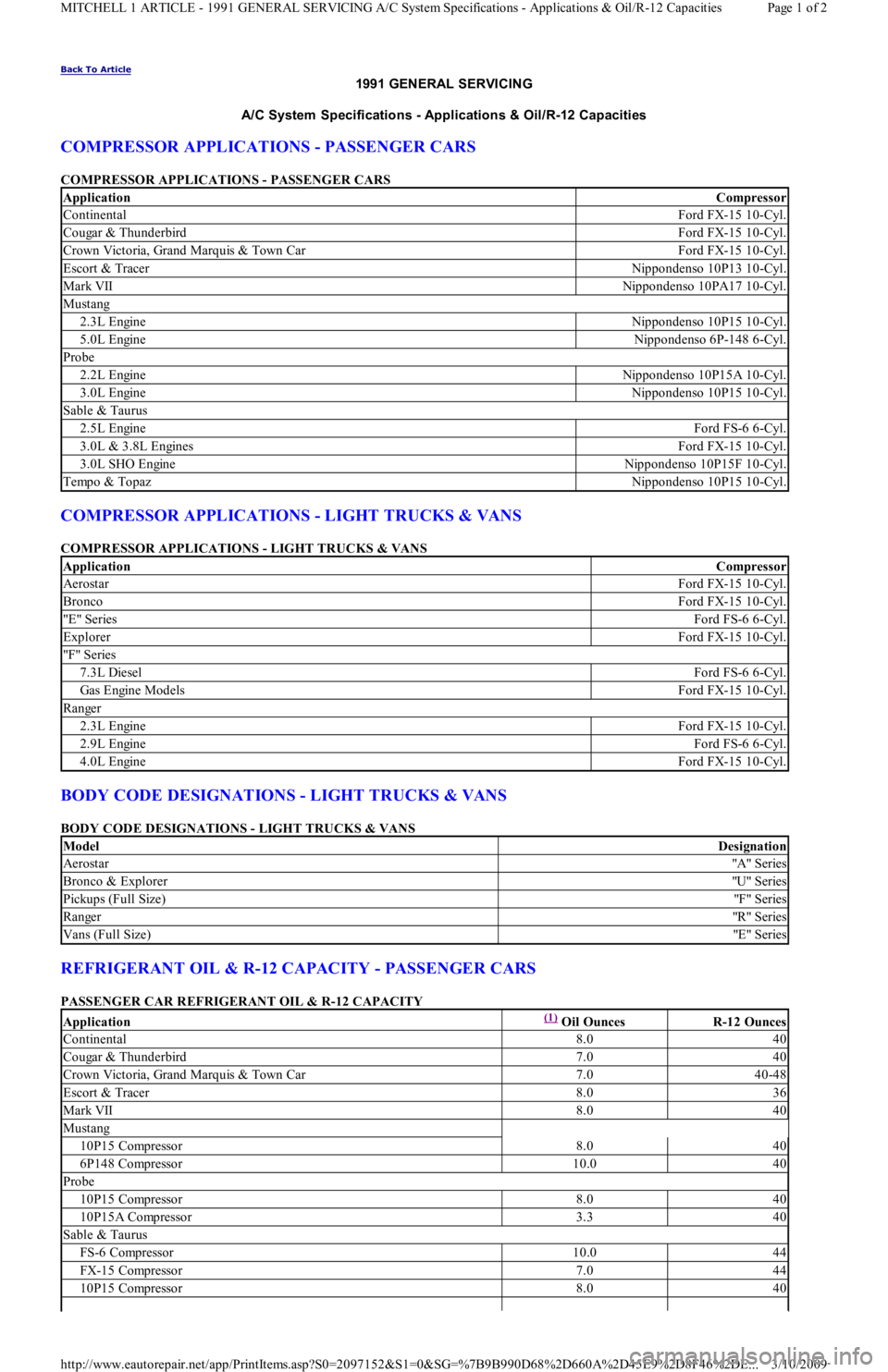
A/C System Specifications - Applications & Oil/R-12 Capacities
COMPRESSOR APPLICATIONS - PASSENGER CARS
COMPRESSOR APPLICATIONS - PASSENGER CARS
COMPRESSOR APPLICATIONS - LIGHT TRUCKS & VANS
COMPRESSOR APPLICATIONS - LIGHT TRUCKS & VANS
BODY CODE DESIGNATIONS - LIGHT TRUCKS & VANS
BODY CODE DESIGNATIONS - LIGHT TRUCKS & VANS
REFRIGERANT OIL & R-12 CAPACITY - PASSENGER CARS
PASSENGER CAR REFRIGERANT OIL & R-12 CAPACITY
ApplicationCompressor
ContinentalFord FX-15 10-Cyl.
Cougar & ThunderbirdFord FX-15 10-Cyl.
Crown Victoria, Grand Marquis & Town CarFord FX-15 10-Cyl.
Escort & TracerNippondenso 10P13 10-Cyl.
Mark VIINippondenso 10PA17 10-Cyl.
Mustang
2.3L EngineNippondenso 10P15 10-Cyl.
5.0L EngineNippondenso 6P-148 6-Cyl.
Probe
2.2L EngineNippondenso 10P15A 10-Cyl.
3.0L EngineNippondenso 10P15 10-Cyl.
Sable & Taurus
2.5L EngineFord FS-6 6-Cyl.
3.0L & 3.8L EnginesFord FX-15 10-Cyl.
3.0L SHO EngineNippondenso 10P15F 10-Cyl.
Tempo & TopazNippondenso 10P15 10-Cyl.
ApplicationCompressor
AerostarFord FX-15 10-Cyl.
BroncoFord FX-15 10-Cyl.
"E " SeriesFord FS-6 6-Cyl.
ExplorerFord FX-15 10-Cyl.
"F" Series
7.3L DieselFord FS-6 6-Cyl.
Gas Engine ModelsFord FX-15 10-Cyl.
Ranger
2.3L EngineFord FX-15 10-Cyl.
2.9L EngineFord FS-6 6-Cyl.
4.0L EngineFord FX-15 10-Cyl.
ModelDesignation
Aerostar"A" Series
Bronco & Explorer"U" Series
Pickups (Full Size)"F" Series
Ranger"R" Series
Vans (Full Size)"E " Series
Application(1) Oil OuncesR-12 Ounces
Continental8.040
Cougar & Thunderbird7.040
Crown Victoria, Grand Marquis & Town Car7.040-48
Escort & Tracer8.036
Mark VII8.040
Mustang
10P15 Compressor8.040
6P148 Compressor10.040
Probe
10P15 Compressor8.040
10P15A Compressor3.340
Sable & Taurus
FS-6 Compressor10.044
FX-15 Compressor7.044
10P15 Compressor8.040
Page 1 of 2 MITCHELL 1 ARTICLE - 1991 GENERAL SERVICING A/C System Specifications - Applications & Oil/R-12 Capacities
3/10/2009 http://www.eautorepair.net/app/PrintItems.asp?S0=2097152&S1=0&SG=%7B9B990D68%2D660A%2D45E9%2D8F46%2DE
...
Page 344 of 454
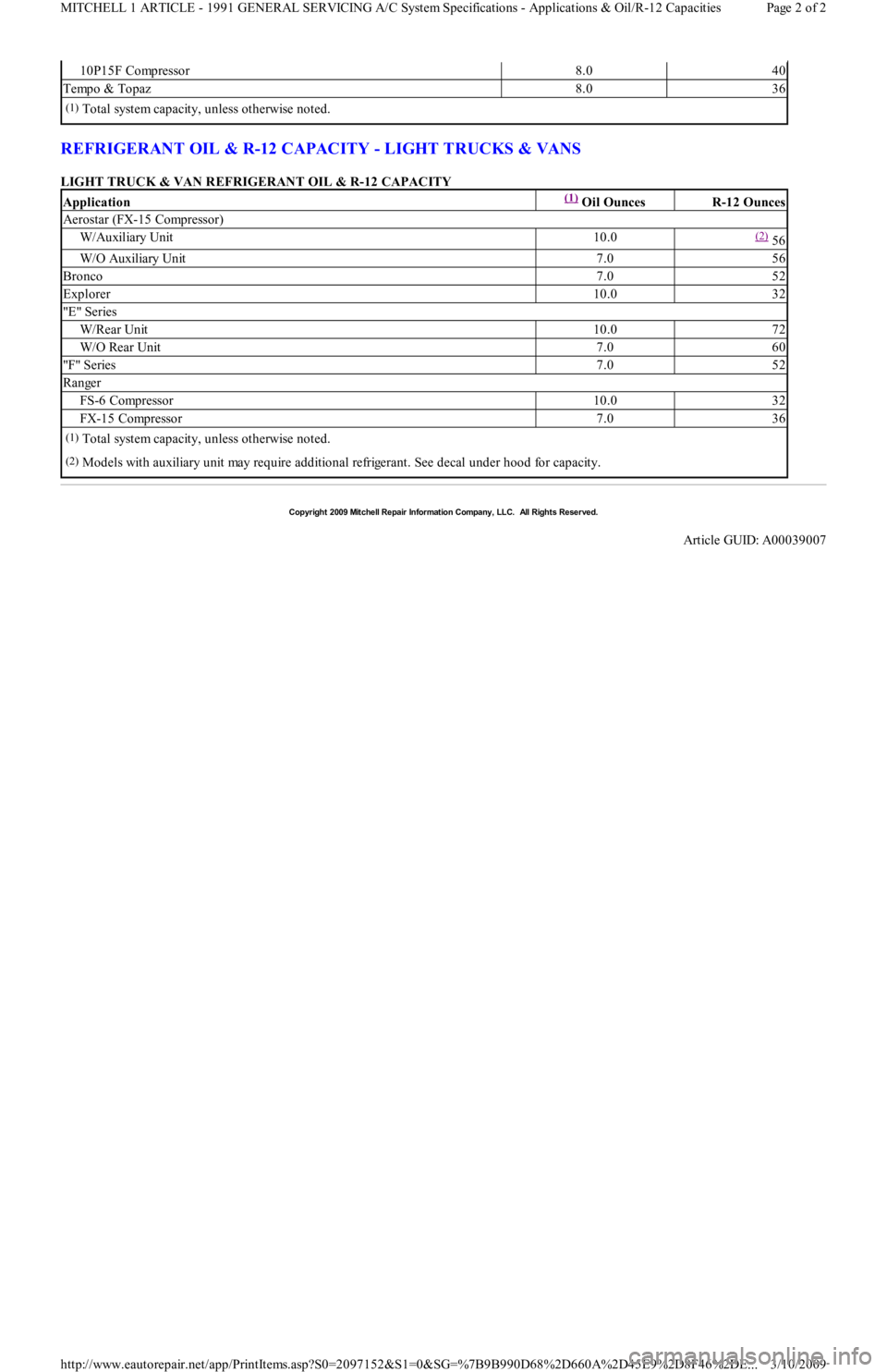
REFRIGERANT OIL & R-12 CAPACITY - LIGHT TRUCKS & VANS
LIGHT TRUCK & VAN REFRIGERANT OIL & R-12 CAPACITY
10P15F Compressor8.040
Tempo & Topaz8.036
(1)Total system capacity, unless otherwise noted.
Application(1) Oil OuncesR-12 Ounces
Aerostar (FX-15 Compressor)
W/Auxiliary Unit10.0(2) 56
W/O Auxiliary Unit7.056
Bronco7.052
Explorer10.032
"E " Series
W/Rear Unit10.072
W/O Rear Unit7.060
"F" Series7.052
Ranger
FS-6 Compressor10.032
FX-15 Compressor7.036
(1)Total system capacity, unless otherwise noted.
(2)Models with auxiliary unit may require additional refrigerant. See decal under hood for capacity.
Copyr ight 2009 Mitchell Repair Information Company, LLC. All Rights Reserved.
Article GUID: A00039007
Page 2 of 2 MITCHELL 1 ARTICLE - 1991 GENERAL SERVICING A/C System Specifications - Applications & Oil/R-12 Capacities
3/10/2009 http://www.eautorepair.net/app/PrintItems.asp?S0=2097152&S1=0&SG=%7B9B990D68%2D660A%2D45E9%2D8F46%2DE
...
Page 436 of 454
Back To Article
T RANSMISSION SERVICING - A/T
1988-93 T RANSMISSION SERVICING Ford Motor Co. Autom atic T ransm ission
IDENTIFICATION
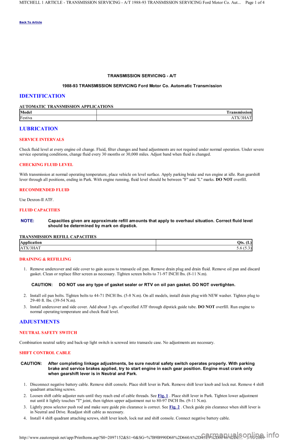
AUTOMATIC TRANSMISSION APPLICATIONS
LUBRICATION
SERVICE INTERVALS
Check fluid level at every engine oil change. Fluid, filter changes and band adjustments are not required under normal operation. Under severe
service operating conditions, change fluid every 30 months or 30,000 miles. Adjust band when fluid is changed.
CHECKING FLUID LEVEL
With transmission at normal operating temperature, place vehicle on level surface. Apply parking brake and run engine at idle. Run gearshift
lever through all positions, ending in Park. With engine running, fluid level should be between "F" and "L" marks. DO NOT overfill.
RECOMMENDED FLUID
Use Dexron-II ATF.
FLUID CAPACITIES
TRANSMISSION REFILL CAPACITIES
DRAINING & REFILLING
1. Remove undercover and side cover to gain access to transaxle oil pan. Remove drain plug and drain fluid. Remove oil pan and discard
gasket. Clean or replace filter screen as necessary. Tighten screen bolts to 71-97 INCH lbs. (8-11 N.m).
2. Install oil pan bolts. Tighten bolts to 44-71 INCH lbs. (5-8 N.m). On all models, install drain plug with NEW washer. Tighten plug to
29-40 ft. lbs. (39-54 N.m).
3. Install undercover and side cover. Add about 3 qts. of specified ATF through dipstick guide tube. DO NOT overfill. Run engine to
normal operating temperature and check fluid level.
ADJUSTMENTS
NEUTRAL SAFETY SWITCH
Combination neutral safety and back-up light switch is screwed into transaxle case. No adjustments are necessary.
SHIFT CONTROL CABLE
1. Disconnect negative battery cable. Remove shift console. Place shift lever in Park. Remove shift lever knob and lock nut. Remove 4 shift
quadrant attaching screws.
2. Loosen shift cable adjuster nuts until they reach end of cable threads. See Fig. 1
. Place shift lever in Park. Tighten lower adjustment
nut until it lightly touches "T" joint, then tighten upper adjustment nut to 80-97 INCH lbs. (9-11 N.m).
3. Lightly press selector push rod and make sure guide pin clearance is correct. See Fig. 2
. Check guide pin clearance when shift lever is
in Neutral and Drive. Readjust shift cable as necessary.
4. Install 4 shift quadrant attaching screws, shift lever knob, lock nut and shift console. Connect negative battery cable.
ModelTransmission
FestivaATX/3HAT
NOTE:Capacities given are approxim ate refill am ounts that apply to overhaul situation. Correct fluid level
should be determ ined by m ark on dipstick.
ApplicationQts. (L)
ATX/3HAT5.6 (5.3)
CAUT ION: DO NOT use any type of gasket sealer or RT V on oil pan gasket. DO NOT overtighten.
CAUT ION: After com pleting linkage adjustm ents, be sure neutral safety switch operates properly. With parking
brake and service brakes applied, try to start engine in each gear position. Engine m ust crank only
when gearshift lever is in Neutral and Park.
Page 1 of 4 MITCHELL 1 ARTICLE - TRANSMISSION SERVICING - A/T 1988-93 TRANSMISSION SERVICING Ford Motor Co. Aut
...
3/10/2009 http://www.eautorepair.net/app/PrintItems.asp?S0=2097152&S1=0&SG=%7B9B990D68%2D660A%2D45E9%2D8F46%2DE
...