1991 FORD FESTIVA stop start
[x] Cancel search: stop startPage 30 of 454
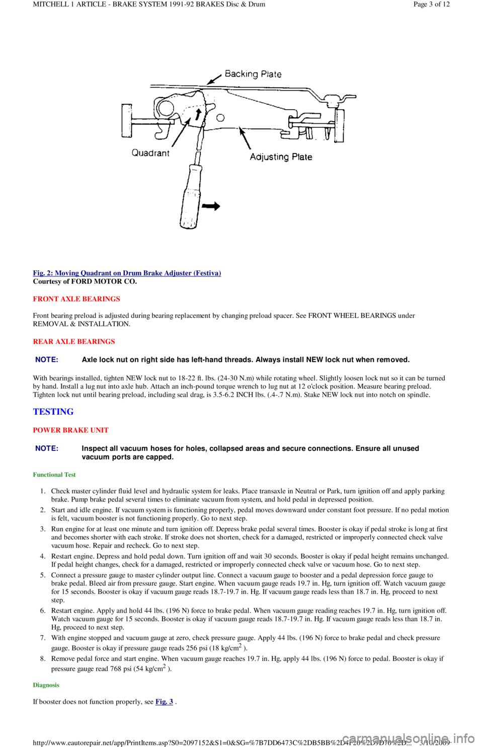
Fig. 2: Moving Quadrant on Drum Brake Adjuster (Festiva)
Courtesy of FORD MOTOR CO.
FRONT AXLE BEARINGS
Front bearing preload is adjusted during bearing replacement by changing preload spacer. See FRONT WHEEL BEARINGS under
REMOVAL & INSTALLATION.
REAR AXLE BEARINGS
With bearings installed, tighten NEW lock nut to 18-22 ft. lbs. (24-30 N.m) while rotating wheel. Slightly loosen lock nut so it can be turned
by hand. Install a lug nut into axle hub. Attach an inch-pound torque wrench to lug nut at 12 o'clock position. Measure bearing preload.
Tighten lock nut until bearing preload, including seal drag, is 3.5-6.2 INCH lbs. (.4-.7 N.m). Stake NEW lock nut into notch on spindle.
TESTING
POWER BRAKE UNIT
Functional Test
1. Check master cylinder fluid level and hydraulic system for leaks. Place transaxle in Neutral or Park, turn ignition off and apply parking
brake. Pump brake pedal several times to eliminate vacuum from system, and hold pedal in depressed position.
2. Start and idle engine. If vacuum system is functioning properly, pedal moves downward under constant foot pressure. If no pedal motion
is felt, vacuum booster is not functioning properly. Go to next step.
3. Run engine for at least one minute and turn ignition off. Depress brake pedal several times. Booster is okay if pedal stroke is long at first
and becomes shorter with each stroke. If stroke does not shorten, check for a damaged, restricted or improperly connected check va l ve
vacuum hose. Repair and recheck. Go to next step.
4. Restart engine. Depress and hold pedal down. Turn ignition off and wait 30 seconds. Booster is okay if pedal height remains unchanged.
If pedal height changes, check for a damaged, restricted or improperly connected check valve or vacuum hose. Go to next step.
5. Connect a pressure gauge to master cylinder output line. Connect a vacuum gauge to booster and a pedal depression force gauge to
brake pedal. Bleed air from pressure gauge. Start engine. When vacuum gauge reads 19.7 in. Hg, turn ignition off. Watch vacuum ga u ge
for 15 seconds. Booster is okay if vacuum gauge reads 18.7-19.7 in. Hg. If vacuum gauge reads less than 18.7 in. Hg, proceed to next
step.
6. Restart engine. Apply and hold 44 lbs. (196 N) force to brake pedal. When vacuum gauge reading reaches 19.7 in. Hg, turn ignition off.
Watch vacuum gauge for 15 seconds. Booster is okay if vacuum gauge reads 18.7-19.7 in. Hg. If vacuum gauge reads less than 18.7 in.
Hg, proceed to next step.
7. With engine stopped and vacuum gauge at zero, check pressure gauge. Apply 44 lbs. (196 N) force to brake pedal and check pressure
gauge. Booster is okay if pressure gauge reads 256 psi (18 kg/cm
2 ).
8. Remove pedal force and start engine. When vacuum gauge reaches 19.7 in. Hg, apply 44 lbs. (196 N) force to pedal. Booster is okay if
pressure gauge read 768 psi (54 kg/cm
2 ).
Diagnosis
If booster does not function properly, see Fig. 3 .
NOTE:Axle lock nut on right side has left-hand threads. Always install NEW lock nut when rem oved.
NOTE:Inspect all vacuum hoses for holes, collapsed areas and secure connections. Ensure all unused
vacuum ports are capped.
Page 3 of 12 MITCHELL 1 ARTICLE - BRAKE SYSTEM 1991-92 BRAKES Disc & Drum
3/10/2009 http://www.eautorepair.net/app/PrintItems.asp?S0=2097152&S1=0&SG=%7B7DD6473C%2DB5BB%2D4F20%2D9D70%2D
...
Page 51 of 454
CATALYTIC CONVERTER
Continued operation of vehicle with a severe malfunction could cause converter to overheat, resulting in possible damage to converter and
ve h ic l e .
Any modification to the exhaust system on turbo models, which reduces exhaust backpressure, will lead to lean fuel mixtures and excessive
spark advance. This could cause serious engine damage.
ELECTROSTATIC DISCHARGE SENSITIVE (ESD) PARTS
ENGINE OIL
FUEL PUMP SHUTOFF SWITCH
This switch stops flow of fuel to engine after a collision. The impact does not have to be great for switch to be triggered. Switch must be reset
after collision. Switch is located under left rear speaker in luggage compartment. Press button to reset switch.
FUEL SYSTEM SERVICE
HALOGEN BULBS
PASSIVE RESTRAINTS
RADIATOR CAP
RADIATOR FAN WARNING:Many solid state electrical com ponents can be dam aged by static electricity (ESD). Som e will display a
warning label, but m any will not. Discharge personal static electricity by touching a m etal ground point
on the vehicle prior to servicing any ESD sensitive com ponent.
CAUT ION: Never use non-detergent or straight m ineral oil.
WARNING:Relieve fuel system pressure prior to servicing any fuel system com ponent (fuel injection m odels).
WARNING:Halogen bulbs contain pressurized gas which m ay explode if overheated. DO NOT touch glass portion
of bulb with bare hands. Eye protection should be worn when handling or working around halogen
bulbs.
CAUT ION: Before operating vehicle, securely fasten passive shoulder restraints to the em ergency release buckles.
T he buckle fits in only one way. Ensure to position it properly.
CAUT ION: Always disconnect the fan m otor when working near the radiator fan. T he fan is tem perature controlled
and could start at any tim e even when the ignition key is in the OFF position. DO NOT loosen or rem ove
radiator cap when cooling system is hot.
WARNING:Keep hands away from radiator fan. Fan is controlled by a therm ostatic switch which m ay com e on or
run for up to 15 m inutes even after engine is turned off.
Copyr ight 2009 Mitchell Repair Information Company, LLC. All Rights Reserved.
Article GUID: A00058075
Page 3 of 3 MITCHELL 1 ARTICLE - FUSES & CIRCUIT BREAKERS Fuses & Circuit Breakers 1988-93 Festiva
3/10/2009 http://www.eautorepair.net/app/PrintItems.asp?S0=2097152&S1=0&SG=%7B7DD6473C%2DB5BB%2D4F20%2D9D70%2D
...
Page 68 of 454

Shift Lock ActuatorShift Interlock Systems
Side Marker LightsExterior Lights
SIR Coil Assembly (Clockspring)Air Bag Restraint System
Slip Ring (Clockspring)Air Bag Restraint System; Steering Column Switches
SRS Control ModuleAir Bag Restraint System
Starter MotorStarters
Starter Interrupt RelayStarters
Starter SolenoidStarters
Starter RelayStarters
Steering Wheel Position SensorAnti-Lock Brakes
StoplightsExterior Lights
Stoplight SwitchEngine Performance; Cruise Control Systems; Anti-Lock Brakes
Sun Roof ECUPower Sun Roof
Sun Roof MotorPower Sun Roof
Sun Roof Position SensorPower Sun Roof
TaillightsExterior Lights
Throttle Position (TP) SensorEngine Performance
Torque Converter Clutch Solenoid/SwitchEngine Performance
Traction Control SwitchAnti-Lock Brakes
Trailer Tow ConnectorExterior Lights
Trailer Tow RelayExterior Lights
Transmission/TransaxleEngine Performance
Transmission Control Module (TCM)Engine Performance; Starters
Transmission Range SensorStarters; Back-Up Lights; Engine Performance
Transmission Range SwitchBack-Up Lights; Engine Performance; Anti-Theft System
Turn Signal FlasherExterior Lights
Tu r n S ign a l Ligh t sExterior Lights
Twilight Sentinel SwitchHeadlight Systems; Daytime Running Lights
Vapor Canister Leak Detection PumpEngine Performance
Vehicle Control Module (VCM)Engine Performance
Vehicle Dynamic ModuleElectronic Suspension
Vehicle Speed Control ServoCruise Control Systems
Vehicle Speed SensorData Link Connectors; Analog Instrument Panels; Cruise Control
Systems; Electronic Suspension
Voltage RegulatorGenerators & Regulators
Water-In-Fuel SensorEngine Performance; Analog Instrument Panels
Wheel Speed SensorsAnti-Lock Brakes
Window Timer ModulePower Convertible Top
Windshield Intermittent Wiper RelayWiper/Washer Systems
Windshield Washer MotorWiper/Washer Systems
Wiper MotorWiper/Washer Systems
Copyr ight 2009 Mitchell Repair Information Company, LLC. All Rights Reserved.
Article GUID: A00130983
Page 6 of 6 MITCHELL 1 ARTICLE - GENERAL INFORMATION Using Mitchell1's Wiring Diagrams
3/10/2009 http://www.eautorepair.net/app/PrintItems.asp?S0=2097152&S1=0&SG=%7B959286D2%2D3A85%2D4BFC%2D9C5C%2D
...
Page 69 of 454
Back To Article
WIRING DIAGRAMS
1991 WIRING DIAGRAMS Ford Motor Co.
IDENTIFICATION
COMPONENT LOCATION MENU
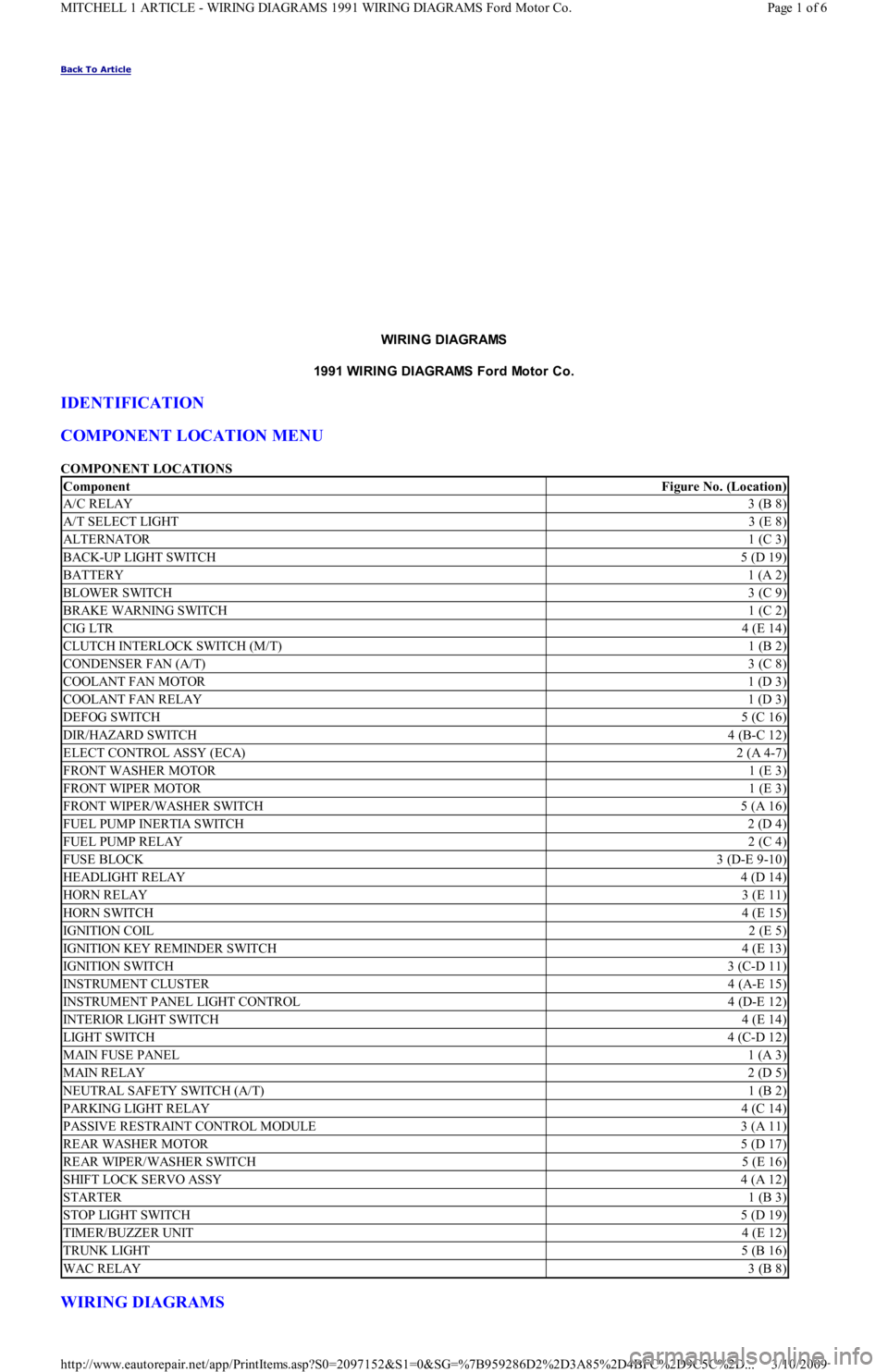
COMPONENT LOCATIONS
WIRING DIAGRAMS
ComponentFigure No. (Location)
A/C RELAY3 (B 8)
A/T SELECT LIGHT3 (E 8)
ALTERNATOR1 (C 3)
BACK-UP LIGHT SWITCH5 (D 19)
BATTERY1 (A 2)
BLOWER SWITCH3 (C 9)
BRAKE WARNING SWITCH1 (C 2)
CIG LTR4 (E 14)
CLUTCH INTERLOCK SWITCH (M/T)1 (B 2)
CONDENSER FAN (A/T)3 (C 8)
COOLANT FAN MOTOR1 (D 3)
COOLANT FAN RELAY1 (D 3)
DEFOG SWITCH5 (C 16)
DIR/HAZARD SWITCH4 (B-C 12)
ELECT CONTROL ASSY (ECA)2 (A 4-7)
FRONT WASHER MOTOR1 (E 3)
FRONT WIPER MOTOR1 (E 3)
FRONT WIPER/WASHER SWITCH5 (A 16)
FUEL PUMP INERTIA SWITCH2 (D 4)
FUEL PUMP RELAY2 (C 4)
FUSE BLOCK3 (D-E 9-10)
HEADLIGHT RELAY4 (D 14)
HORN RELAY3 (E 11)
HORN SWITCH4 (E 15)
IGNITION COIL2 (E 5)
IGNITION KEY REMINDER SWITCH4 (E 13)
IGNITION SWITCH3 (C-D 11)
INSTRUMENT CLUSTER4 (A-E 15)
INSTRUMENT PANEL LIGHT CONTROL4 (D-E 12)
INTERIOR LIGHT SWITCH4 (E 14)
LIGHT SWITCH4 (C-D 12)
MAIN FUSE PANEL1 (A 3)
MAIN RELAY2 (D 5)
NEUTRAL SAFETY SWITCH (A/T)1 (B 2)
PARKING LIGHT RELAY4 (C 14)
PASSIVE RESTRAINT CONTROL MODULE3 (A 11)
REAR WASHER MOTOR5 (D 17)
REAR WIPER/WASHER SWITCH5 (E 16)
SHIFT LOCK SERVO ASSY4 (A 12)
STARTER1 (B 3)
STOP LIGHT SWITCH5 (D 19)
TIMER/BUZZER UNIT4 (E 12)
TRUNK LIGHT5 (B 16)
WAC RELAY3 (B 8)
Page 1 of 6 MITCHELL 1 ARTICLE - WIRING DIAGRAMS 1991 WIRING DIAGRAMS Ford Motor Co.
3/10/2009 http://www.eautorepair.net/app/PrintItems.asp?S0=2097152&S1=0&SG=%7B959286D2%2D3A85%2D4BFC%2D9C5C%2D
...
Page 129 of 454
Back To Article
D - ADJUSTMENTS
1991 ENGINE PERFORMANCE Ford/Mercury - On-Vehicle Adjustm ents
ADJUSTMENTS
ENGINE MECHANICAL
Before beginning any on-vehicle adjustments to fuel or ignition systems, ensure engine mechanical condition is okay.
VALVE CLEARANCE
IGNITION TIMING
CAPRI
1. Place automatic transmission in Park or manual transmission in Neutral. Disconnect and plug hoses attached to vacuum diaphragm
assembly on distributor. Connect tachometer and timing light. Turn off all electrical loads.
2. Start engine, and warm it to operating temperature. Ensure idle speed is set to specification, adjusting if necessary. See IDLE SPEED &
MIXTURE . Determine initial timing. See IGNITION TIMING table. If base timing is not correct, loosen distributor mounting bolts
and rotate distributor until marks align. Tighten bolts to 14-18 ft. lbs. (19-25 N.m).
3. Increase engine RPM while observing timing light. Verify ignition timing advances. For Turbo models, go to step 5). For non-Turbo
models, continue with step 4).
4. On non-Turbo models, apply 16 in. Hg vacuum to chamber "A". Verify timing advances by 26-30 degrees. Remove vacuum source from
chamber "A". Apply 8 in. Hg vacuum to chamber "B" while observing timing. Verify timing advances by 3-7 degrees. Stop engine, and
remove test equipment.
5. On Turbo models, apply 20 in. Hg vacuum to advance diaphragm. Verify timing advances by 13-17 degrees. Disconnect vacuum source.
Apply 8 psi (.6 kg/cm
2 ) pressure to advance diaphragm. Verify timing retards by 3-7 degrees. Stop engine, and remove test equipment.
FESTIVA
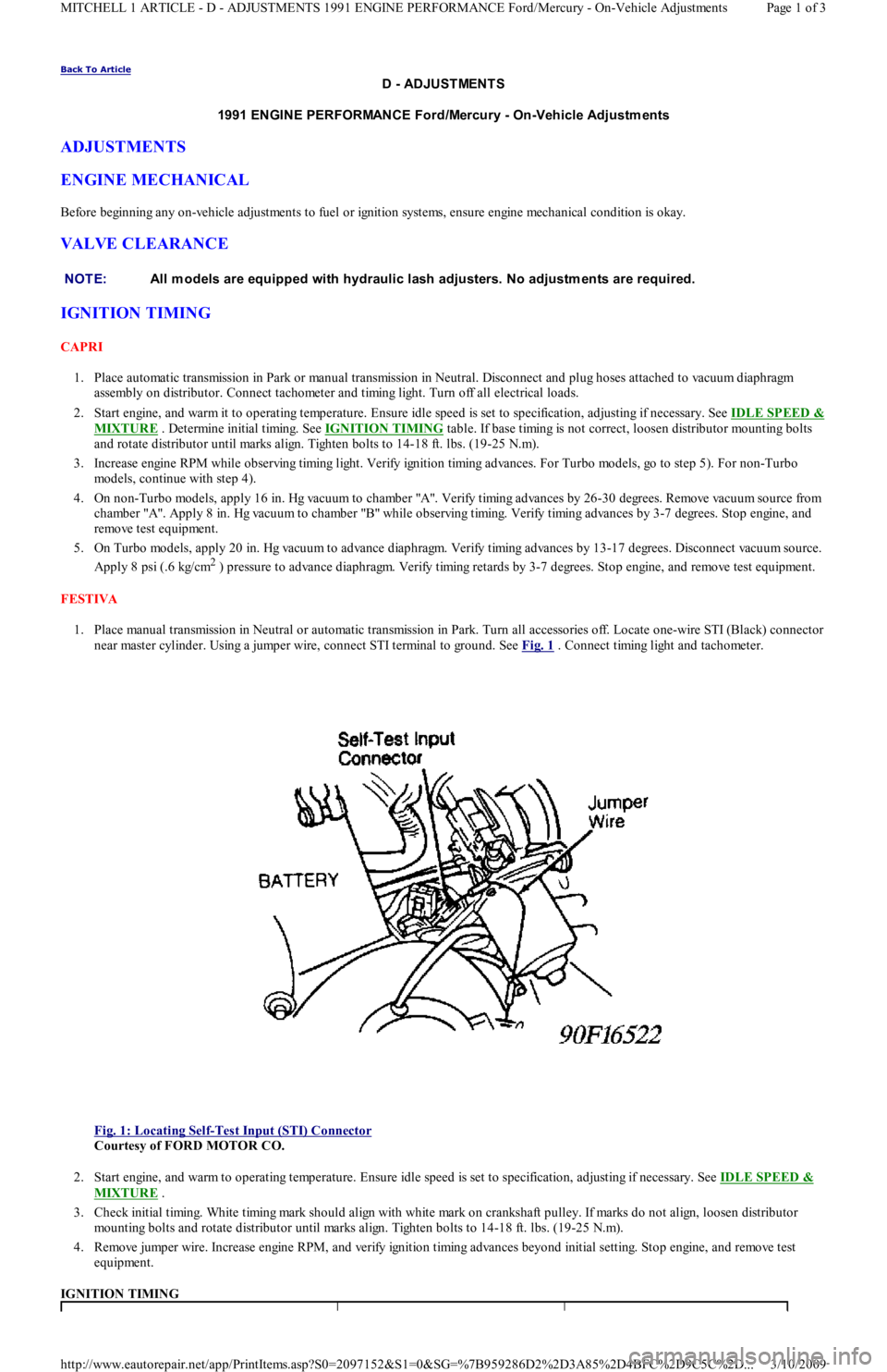
1. Place manual transmission in Neutral or automatic transmission in Park. Turn all accessories off. Locate one-wire STI (Black) connector
near master cylinder. Using a jumper wire, connect STI terminal to ground. See Fig. 1
. Connect timing light and tachometer.
Fig. 1: Locating Self
-Test Input (STI) Connector
Courtesy of FORD MOTOR CO.
2. Start engine, and warm to operating temperature. Ensure idle speed is set to specification, adjusting if necessary. See IDLE SPEED &
MIXTURE .
3. Check initial timing. White timing mark should align with white mark on crankshaft pulley. If marks do not align, loosen distributor
mounting bolts and rotate distributor until marks align. Tighten bolts to 14-18 ft. lbs. (19-25 N.m).
4. Remove jumper wire. Increase engine RPM, and verify ignition timing advances beyond initial setting. Stop engine, and remove test
equipment.
IGNITION TIMING NOTE:All m odels are equipped with hydraulic lash adjusters. No adjustm ents are required.
Page 1 of 3 MITCHELL 1 ARTICLE - D - ADJUSTMENTS 1991 ENGINE PERFORMANCE Ford/Mercury - On-Vehicle Adjustments
3/10/2009 http://www.eautorepair.net/app/PrintItems.asp?S0=2097152&S1=0&SG=%7B959286D2%2D3A85%2D4BFC%2D9C5C%2D
...
Page 163 of 454

POWER STEERING PRESSURE SWITCH
1. Start engine and run it at idle. Remove connector from switch. Connect ohmmeter to switch terminals. Turn steering wheel from side to
side while observing ohmmeter.
2. Replace power steering switch if continuity does not exist with front wheels turned, or if continuity exists with wheels straight ahead.
THROTTLE POSITION SENSOR (1.6L)
Unplug connector from sensor. Connect ohmmeter to sensor terminals TP and SIGRTN (Orange and Blue/Yellow wires on mating connector).
Measure resistance at each throttle opening specified in THROTTLE POSITION SENSOR RESISTANCE
. Replace sensor if resistance is
not within specification.
THROTTLE POSITION SENSOR RESISTANCE
THROTTLE POSITION SWITCH (1.3L)
1. Ensure idle speed and ignition timing are adjusted to specification. Stop engine. Disconnect negative battery cable.
2. Unplug TPS connector at throttle body. Insert appropriate feeler gauge between throttle stop screw and stop lever. Check for continuity
between specified terminals on TPS connector. See ON-VEHICLE ADJUSTMENTS article and TPS CONTINUITY table.
TPS CONTINUITY
VANE AIRFLOW (VAF) METER
1. Check all wiring, harnesses, connectors and components for evidence of damage, overheating, shorting or looseness. If any defect exists,
repair as necessary.
2. Inspect vane airflow meter for damage and ensure measuring plate moves smoothly. Install BOB. Turn ignition on. Measure voltage
between BOB test pins VAF and ground on 1.3L, or between VAF and SIGRTN on 1.6L. Voltage measurements must be as specified in
VANE AIRFLOW METER VOLTAG
.
VANE AIRFLOW METER VOLTAGE
VANE AIR TEMPERATURE (VAT) SENSOR
1. Unplug connector from VAF meter. On 1.3L, connect ohmmeter to terminals VAT and ground (Green/Black and Black wires on mating
connector). On 1.6L, connect ohmmeter to VAF meter terminals VAT and SIGRTN (Brown and Blue/Yellow wires on mating
connector).
2. Measure intake air temperature. Measure resistance between specified terminals. See VANE AIR TEMPERATURE RESISTANCE
.
Replace VAF if resistance is not as specified.
Throttle Opening(1) Ohms
1/8989
1/41104
3/81278
1/21462
5/81480
3/41459
7/81144
Fully Open1072
(1)Resistance may vary by plus or minus 15 percent.
CAUT ION: DO NOT tam per with throttle stop screw at throttle lever. Doing so m ay result in dam age to the
throttle body.
Test Condition (1) Cont. Between IDL-TLCont. Between PSW-TL
.02" (.5 mm)YesNo
.03" (.7 mm)NoNo
Wide Open ThrottleNoYes
(1)Insert specified feeler gauge between throttle adjustment screw and stop lever.
Door Opening(1) Volts: 1.3L(1) Volts: 1.6L
Fully Closed.5-1.5(2) *
1/8.593.24
1/41.195.60
3/81.785.62
1/22.385.83
5/82.976.02
3/43.566.57
7/84.167.48
Fully Open4.5-5.07.87
(1)Voltage may vary by plus or minus 15 percent.
(2)Voltage not specified.
Page 3 of 7 MITCHELL 1 ARTICLE - I - SYSTEM/COMPONENT TESTS 1991 ENGINE PERFORMANCE Ford Motor Co. - Ford/Merc
...
3/10/2009 http://www.eautorepair.net/app/PrintItems.asp?S0=2097152&S1=0&SG=%7B7DD6473C%2DB5BB%2D4F20%2D9D70%2D
...
Page 166 of 454
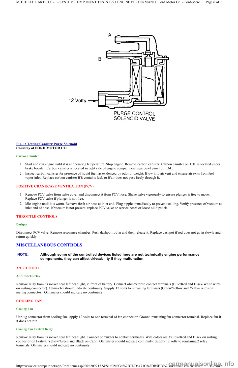
Fig. 1: Testing Canister Purge Solenoid
Courtesy of FORD MOTOR CO.
Carbon Canister
1. Start and run engine until it is at operating temperature. Stop engine. Remove carbon canister. Carbon canister on 1.3L is located under
brake booster. Carbon canister is located in right side of engine compartment near cowl panel on 1.6L.
2. Inspect carbon canister for presence of liquid fuel, as evidenced by odor or weight. Blow into air vent and ensure air exits fro m fu el
vapor inlet. Replace carbon canister if it contains fuel, or if air does not pass freely through it.
POSITIVE CRANKCASE VENTILATION (PCV)
1. Remove PCV valve from valve cover and disconnect it from PCV h o se . S h a ke va l ve vigo r o u sl y t o e n su r e p l u n ge r is fr e e t o mo ve .
Replace PCV valve if plunger is not free.
2. Idle engine until it is warm. Remove fresh air hose at inlet end. Plug nipple immediately to prevent stalling. Verify presence of vacuum at
inlet end of hose. If vacuum is not present, replace PCV valve or service hoses or loose oil dipstick.
THROTTLE CONTROLS
Dashpot
Disconnect PCV valve. Remove resonance chamber. Push dashpot rod in and then release it. Replace dashpot if rod does not go in slowly and
return quickly.
MISCELLANEOUS CONTROLS
A/C CLUTCH
A/C Clutch Relay
Remove relay from its socket near left headlight, in front of battery. Connect ohmmeter to contact terminals (Blue/Red and Black/White wires
on mating connector). Ohmmeter should indicate continuity. Supply 12 volts to remaining terminals (Green/Yellow and Yellow wires on
mating connector). Ohmmeter should indicate no continuity.
COOLING FAN
Cooling Fan
Unplug connector from cooling fan. Apply 12 volts to one terminal of fan connector. Ground remaining fan connector terminal. Replace fan if
it does not run.
Cooling Fan Control Relay
Remove relay from its socket near left headlight. Connect ohmmeter to contact terminals. Wire colors are Yellow/Red and Black on mating
connector on Festiva; Yellow/Green and Black on Capri. Ohmmeter should indicate continuity. Supply 12 volts to remaining 2 relay
terminals. Ohmmeter should indicate no continuity.
NOTE:Although som e of the controlled devices listed here are not technically engine perform ance
com ponents, they can affect driveability if they m alfunction.
Page 6 of 7 MITCHELL 1 ARTICLE - I - SYSTEM/COMPONENT TESTS 1991 ENGINE PERFORMANCE Ford Motor Co. - Ford/Merc
...
3/10/2009 http://www.eautorepair.net/app/PrintItems.asp?S0=2097152&S1=0&SG=%7B7DD6473C%2DB5BB%2D4F20%2D9D70%2D
...
Page 252 of 454
Back To Article
GENERAL INFORMATION
Com puter Relearn Procedures
COMPUTER RELEARN PROCEDURES
Vehicles equipped with engine or transmission computers may require a relearn procedure after vehicle battery is disconnected. Many vehicle
computers memorize and store vehicle operation patterns for optimum driveability and performance. When vehicle battery is disconnected,
this memory is lost. The computer will use default data until new data from each key start is stored. As computer memorizes vehicle operation
for each new key start, driveability is restored. Vehicle computers may memorize vehicles operation patterns for 40 of more key starts.
Customers often complain of driveability problems during relearn stage because vehicle acts differently then before being serviced. Depending
on type and make of vehicle and how it is equipped, the following complaints (driveability problems) may exist:
Harsh Or Poor Shift Quality
Rough Or Unstable Idle
Hesitation Or Stumble
Rich Or Lean Running
Poor Fuel Mileage
These symptoms and complaints should disappear after a number of drive cycles have been memorized. To reduce the possibility of
complaints, after any service which requires battery power to be disconnected, vehicle should be road tested.
GENERIC COMPUTER RELEARN PROCEDURES
Some manufacturers identify a specific relearn procedure which will help establish suitable driveability during relearn stage. These procedures
are especially important if vehicle is equipped with and electronically controlled automatic transmission or transaxle. Always complete
procedure before returning vehicle to customer. The following general procedures are to be used if driveability problems are encountered after
power loss or battery has been disconnected. These procedures may provide an aid in eliminating these problems.
Automatic Transmission
Set parking brake, start engine in "P" or "N" position. Warm-up vehicle to normal operating temperature or until cooling fan cycles.
Allow vehicle to idle for one minute in "N" position. Select "D" and allow engine to idle for one minute.
Accelerate at normal throttle position (20-50%) until vehicle shifts into top gear.
Cruise at light to medium throttle.
Decelerate to a stop, allowing vehicle to downshift, and use brakes normally.
Process may be repeated as necessary.
Manual Transmission
Place transmission in Neutral position.
Ensure emergency brake has been set and all accessories are turned off.
Start engine and bring to normal operating temperature.
Allow vehicle to idle in Neutral for one minute.
Initial relearn is complete, and process will be completed during normal driving.
Copyr ight 2009 Mitchell Repair Information Company, LLC. All Rights Reserved.
Article GUID: A00012612
Page 1 of 1 MITCHELL 1 ARTICLE - GENERAL INFORMATION Computer Relearn Procedures
3/10/2009 http://www.eautorepair.net/app/PrintItems.asp?S0=2097152&S1=0&SG=%7B9B990D68%2D660A%2D45E9%2D8F46%2DE
...