1991 FORD FESTIVA radiator cap
[x] Cancel search: radiator capPage 6 of 454
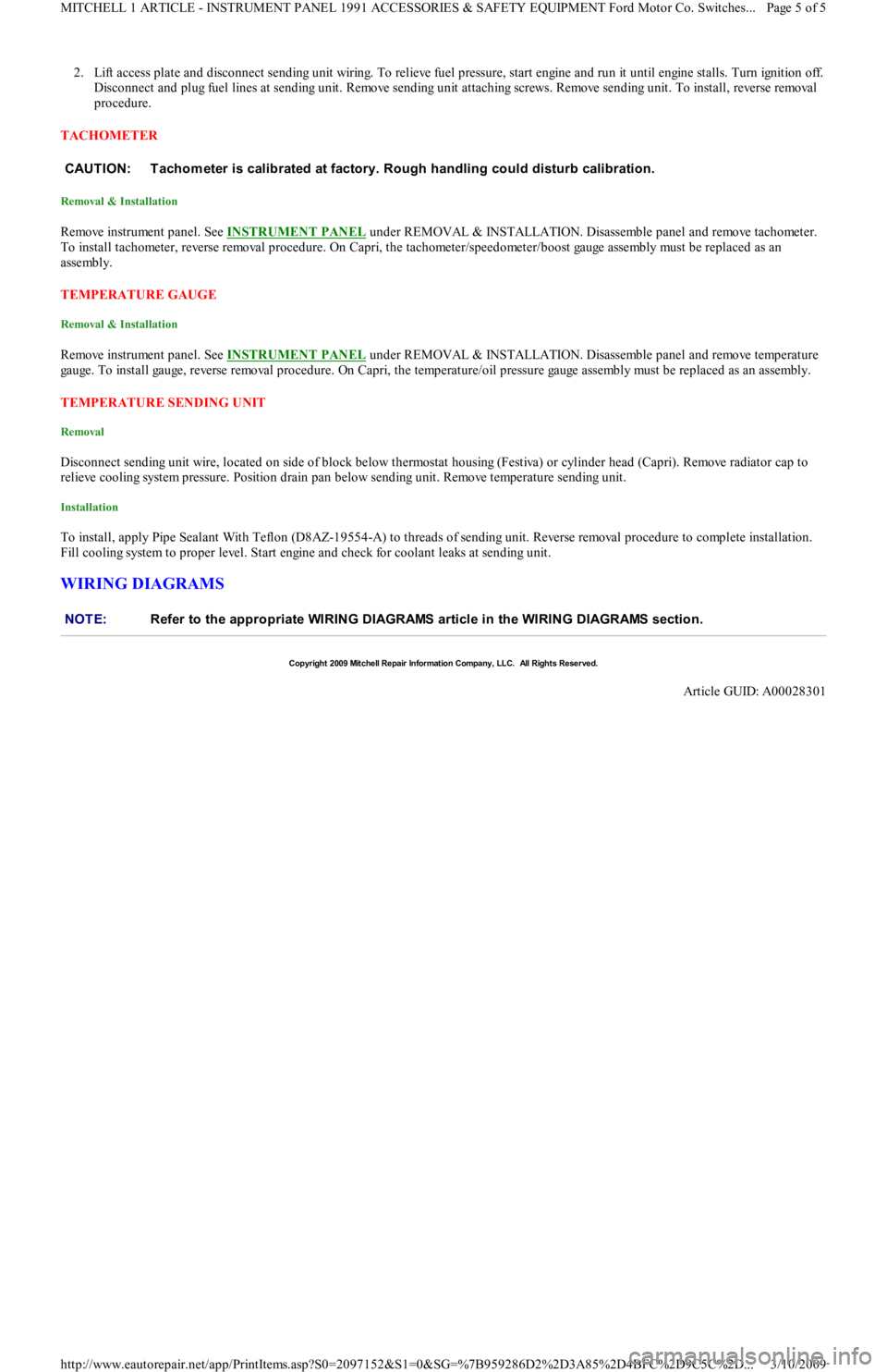
2. Lift access plate and disconnect sending unit wiring. To relieve fuel pressure, start engine and run it until engine stalls. Turn ignition off.
Disconnect and plug fuel lines at sending unit. Remove sending u n it a t t a c h in g sc r e ws. R e mo ve se n d in g u n it . To in st a l l , r e ve r se removal
procedure.
TACHOMETER
Removal & Installation
Remo ve in st ru men t p an el . See INSTRUMENT PANEL under REMOVAL & INSTALLATION. Disassemble panel and remove tachometer.
To install tachometer, reverse removal procedure. On Capri, the tachometer/speedometer/boost gauge assembly must be replaced as an
assembly.
TEMPERATURE GAUGE
Removal & Installation
Remo ve in st ru men t p an el . See INSTRUMENT PANEL under REMOVAL & INSTALLATION. Disassemble panel and remove temperature
gauge. To install gauge, reverse removal procedure. On Capri, the temperature/oil pressure gauge assembly must be replaced as an assembly.
TEMPERATURE SENDING UNIT
Removal
Disconnect sending unit wire, located on side of block below thermostat housing (Festiva) or cylinder head (Capri). Remove radiator cap to
relieve cooling system pressure. Position drain pan below sending unit. Remove temperature sending unit.
Installation
To install, apply Pipe Sealant With Teflon (D8AZ-19554-A) to threads of sending unit. Reverse removal procedure to complete installation.
Fill cooling system to proper level. Start engine and check for coolant leaks at sending unit.
WIRING DIAGRAMS
CAUT ION: T achom eter is calibrated at factory. Rough handling could disturb calibration.
NOTE:Refer to the appropriate WIRING DIAGRAMS article in the WIRING DIAGRAMS section.
Copyr ight 2009 Mitchell Repair Information Company, LLC. All Rights Reserved.
Article GUID: A00028301
Page 5 of 5 MITCHELL 1 ARTICLE - INSTRUMENT PANEL 1991 ACCESSORIES & SAFETY EQUIPMENT Ford Motor Co. Switches
...
3/10/2009 http://www.eautorepair.net/app/PrintItems.asp?S0=2097152&S1=0&SG=%7B959286D2%2D3A85%2D4BFC%2D9C5C%2D
...
Page 51 of 454
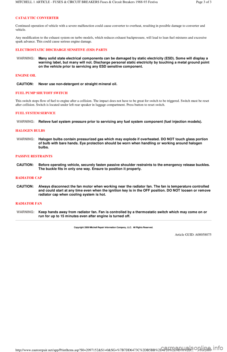
CATALYTIC CONVERTER
Continued operation of vehicle with a severe malfunction could cause converter to overheat, resulting in possible damage to converter and
ve h ic l e .
Any modification to the exhaust system on turbo models, which reduces exhaust backpressure, will lead to lean fuel mixtures and excessive
spark advance. This could cause serious engine damage.
ELECTROSTATIC DISCHARGE SENSITIVE (ESD) PARTS
ENGINE OIL
FUEL PUMP SHUTOFF SWITCH
This switch stops flow of fuel to engine after a collision. The impact does not have to be great for switch to be triggered. Switch must be reset
after collision. Switch is located under left rear speaker in luggage compartment. Press button to reset switch.
FUEL SYSTEM SERVICE
HALOGEN BULBS
PASSIVE RESTRAINTS
RADIATOR CAP
RADIATOR FAN WARNING:Many solid state electrical com ponents can be dam aged by static electricity (ESD). Som e will display a
warning label, but m any will not. Discharge personal static electricity by touching a m etal ground point
on the vehicle prior to servicing any ESD sensitive com ponent.
CAUT ION: Never use non-detergent or straight m ineral oil.
WARNING:Relieve fuel system pressure prior to servicing any fuel system com ponent (fuel injection m odels).
WARNING:Halogen bulbs contain pressurized gas which m ay explode if overheated. DO NOT touch glass portion
of bulb with bare hands. Eye protection should be worn when handling or working around halogen
bulbs.
CAUT ION: Before operating vehicle, securely fasten passive shoulder restraints to the em ergency release buckles.
T he buckle fits in only one way. Ensure to position it properly.
CAUT ION: Always disconnect the fan m otor when working near the radiator fan. T he fan is tem perature controlled
and could start at any tim e even when the ignition key is in the OFF position. DO NOT loosen or rem ove
radiator cap when cooling system is hot.
WARNING:Keep hands away from radiator fan. Fan is controlled by a therm ostatic switch which m ay com e on or
run for up to 15 m inutes even after engine is turned off.
Copyr ight 2009 Mitchell Repair Information Company, LLC. All Rights Reserved.
Article GUID: A00058075
Page 3 of 3 MITCHELL 1 ARTICLE - FUSES & CIRCUIT BREAKERS Fuses & Circuit Breakers 1988-93 Festiva
3/10/2009 http://www.eautorepair.net/app/PrintItems.asp?S0=2097152&S1=0&SG=%7B7DD6473C%2DB5BB%2D4F20%2D9D70%2D
...
Page 101 of 454
Back To Article
ENGINE OVERHAUL
1991-92 FORD MOT OR CO. ENGINES 1.3L & 1.6L 4-Cylinder
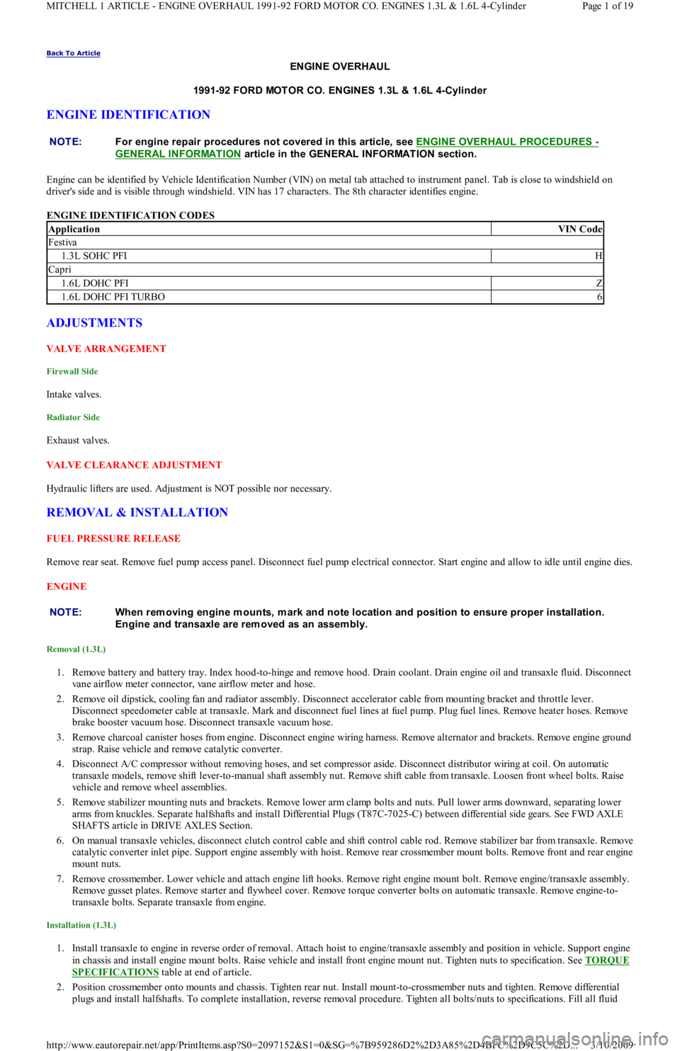
ENGINE IDENTIFICATION
Engine can be identified by Vehicle Identification Number (VIN) on metal tab attached to instrument panel. Tab is close to windshield on
driver's side and is visible through windshield. VIN has 17 characters. The 8th character identifies engine.
ENGINE IDENTIFICATION CODES
ADJUSTMENTS
VALVE ARRANGEMENT
Firewall Side
In t ake val ves.
Radiator Side
Exhaust valves.
VALVE CLEARANCE ADJUSTMENT
Hydraulic lifters are used. Adjustment is NOT possible nor necessary.
REMOVAL & INSTALLATION
FUEL PRESSURE RELEASE
Remove rear seat. Remove fuel pump access panel. Disconnect fuel pump electrical connector. Start engine and allow to idle until engine dies.
ENGINE
Removal (1.3L)
1. Remove battery and battery tray. Index hood-to-hinge and remove hood. Drain coolant. Drain engine oil and transaxle fluid. Disconnect
vane airflow meter connector, vane airflow meter and hose.
2. Remove oil dipstick, cooling fan and radiator assembly. Disconnect accelerator cable from mounting bracket and throttle lever.
Disconnect speedometer cable at transaxle. Mark and disconnect fuel lines at fuel pump. Plug fuel lines. Remove heater hoses. Remove
brake booster vacuum hose. Disconnect transaxle vacuum hose.
3. Remove charcoal canister hoses from engine. Disconnect engine wiring harness. Remove alternator and brackets. Remove engine ground
strap. Raise vehicle and remove catalytic converter.
4. Disconnect A/C compressor without removing hoses, and set compressor aside. Disconnect distributor wiring at coil. On automatic
transaxle models, remove shift lever-to-manual shaft assembly nut. Remove shift cable from transaxle. Loosen front wheel bolts. Raise
vehicle and remove wheel assemblies.
5. Remove stabilizer mounting nuts and brackets. Remove lower arm clamp bolts and nuts. Pull lower arms downward, separating lower
arms from knuckles. Separate halfshafts and install Differential Plugs (T87C-7025-C) between differential side gears. See FWD AXLE
SHAFTS article in DRIVE AXLES Section.
6. On manual transaxle vehicles, disconnect clutch control cable and shift control cable rod. Remove stabilizer bar from transaxle. Remove
catalytic converter inlet pipe. Support engine assembly with hoist. Remove rear crossmember mount bolts. Remove front and rear engine
mount nuts.
7. Remove crossmember. Lower vehicle and attach engine lift hooks. Remove right engine mount bolt. Remove engine/transaxle assembly.
Remove gusset plates. Remove starter and flywheel cover. Remove torque converter bolts on automatic transaxle. Remove engine-to-
transaxle bolts. Separate transaxle from engine.
Installation (1.3L)
1. Install transaxle to engine in reverse order of removal. Attach hoist to engine/transaxle assembly and position in vehicle. Support engine
in chassis and install engine mount bolts. Raise vehicle and install front engine mount nut. Tighten nuts to specification. See TORQUE
SPECIFICATIONS table at end of article.
2. Position crossmember onto mounts and chassis. Tighten rear nut. Install mount-to-crossmember nuts and tighten. Remove differential
plugs and install halfshafts. To complete installation, reverse removal procedure. Tighten all bolts/nuts to specifications. Fill all fluid NOTE:For engine repair procedures not covered in this article, see ENGINE OVERHAUL PROCEDURES
-
GENERAL INFORMATION
article in the GENERAL INFORMAT ION section.
ApplicationVIN Code
Festiva
1.3L SOHC PFIH
Capri
1.6L DOHC PFIZ
1.6L DOHC PFI TURBO6
NOTE:When rem oving engine m ounts, m ark and note location and position to ensure proper installation.
Engine and transaxle are rem oved as an assem bly.
Page 1 of 19 MITCHELL 1 ARTICLE - ENGINE OVERHAUL 1991-92 FORD MOTOR CO. ENGINES 1.3L & 1.6L 4-Cylinder
3/10/2009 http://www.eautorepair.net/app/PrintItems.asp?S0=2097152&S1=0&SG=%7B959286D2%2D3A85%2D4BFC%2D9C5C%2D
...
Page 102 of 454

levels to proper level.
Removal (1.6L & 1.6L Turbo)
1. Relieve fuel pressure and discharge air conditioning system (if equipped). See FUEL PRESSURE RELEASE under REMOVAL &
INSTALLATION. Disconnect and remove battery, battery tray and battery tray support bracket.
2. Release wiring harness retaining straps from battery support tray. Disconnect windshield washer supply hose between fluid reservoir and
hood. Mark hinge locations and remove hood.
3. Disconnect intake air tube and wiring to ignition coil and vane airflow meter. Remove air cleaner/vane airflow meter assembly. Remove
air cleaner assembly support brackets. Disconnect intercooler hoses from turbocharger (if equipped).
4. Drain engine coolant and remove radiator. Disconnect accelerator cable, and remove retaining bracket from cam cover. Position cable to
one side.
5. Disconnect and plug fuel lines at fuel filter and pressure regulator. Disconnect power brake booster manifold vacuum hose from
manifold. Disconnect heater hoses at heater core tubes. Label and remove vacuum hoses located at throttle body.
6. For manual transaxle turbocharged vehicles, disconnect clutch cable and remove support bracket and cable from transmission. On non-
turbo vehicles, disconnect clutch slave hydraulic line. For automatic transaxle, remove transaxle cooler lines.
7. Disconnect starter wiring at starter. Remove harness from locating strap on bracket. Disconnect alternator wiring. Disconnect wiring
from engine coolant sensors located on rear of engine block. Remove ground connection at bracket on thermostat cover. Disconnect O2
sensor wire, main wiring harness connector, TPS connector (turbocharged only), knock sensor connector, distributor wiring and
transaxle wiring. Disconnect ground wire and strap at front of engine, and reinstall lifting eye.
8. Remove engine oil dipstick and retaining clip. Remove power steering pump from mounting bracket. Remove power steering pump
mounting bracket. With hoses attached, position pump aside. Remove upper air conditioning compressor retaining bolts (if equipped).
9. Raise vehicle on hoist. Drain engine oil and cooling system. On vehicles with air conditioning, remove lower air conditioning
compressor mounting bolts, and position compressor out of way.
10. Remove front wheels and tires. Remove front ball joints-to-ste e r in g kn u c kl e s r e t a in in g b o l t s. R e mo ve sp l a sh gu a r d s. Dr a in t ransmission
oil and remove half shafts from differential. Remove front exhaust pipe bracket located on lower side of engine. Disconnect front
exhaust pipe from exhaust manifold, or turbocharger (if equipped).
11. Remove frame support bar-to-engine support bolt. Loosen right control arm bolt and, pivot support bar downward. Disengage rubber
exhaust hangers located directly behind catalytic converter. Allow exhaust system to hang down 6 inches, and support system with
mechanic's wire. Unbolt shift linkage and stabilizer bar at transaxle. Remove nuts from front and rear engine mounts, and lower vehicle.
12. Attach chains onto lift eyes at ends of cylinder head, and support engine with hoist. Remove RH engine mount through bolt. Raise
engine off mounts and slightly pivot engine/transaxle assembly. Disconnect oil pressure sensor and route starter/alternator wiring
harness from engine. Carefully lift engine/transaxle assembly, turn assembly while raising to clear brake master cylinder, shift linkage
universal joint, radiator support and air conditioning lines (if equipped).
13. Remove intake manifold support bracket. Remove gusset plate(s) (if equipped). Remove starter. Remove transaxle-to-engine retaining
bolts. Identify bolts to ensure correct installation. Separate transaxle from engine. On manual transaxle, remove pressure plate, clutch
disc and flywheel. On automatic transaxle, remove flexplate.
Installation (1.6L & 1.6L Turbo)
1. Install transaxle to engine in reverse order of removal. Attach hoist to engine/transaxle assembly and position assembly in vehicle.
Before engine contacts mounts, route starter, alternator and oil pressure sensor wiring, and connect oil pressure sensor. Lower engine
until front mount seats on crossmember. Install through bolt on RH engine mount. DO NOT tighten bolt.
2. Remove hoist. Raise vehicle and support with jackstands. Align rear engine mount to crossmember, and install retaining nuts to front
and rear engine mounts. Tighten nuts to specification. See TORQUE SPECIFICATIONS
table at end of article.
3. On manual transaxles, connect shift coupling and stabilizer. Tighten to specification. On automatic transaxles, connect shift linkage and
oil cooler lines. Tighten linkage retaining bolt, shift cable pivot and oil cooler hose clamps to specification. Connect front exhaust pipe
to manifold (or turbocharger). Install exhaust pipe to support bracket. Tighten bolts to specification. Tighten manifold (or turbocharger)
to specification. Attach rubber exhaust hangers. Position cross brace. Tighten retaining nut and bolt and right control arm front bolt.
4. Install drive axles. Install ball joint retaining bolts and tighten to specification. Mount A/C Compressor to engine (if equipped). Tighten
lower retaining bolts to specification. Install splash guards. Install tire and wheel assemblies. Tighten retaining nuts to specification.
5. Lower vehicle. Install upper A/C compressor retaining bolts (if equipped). Tighten bolts to specification. Tighten RH engine mo u n t
through bolt to specification. Connect alternator wiring.
6. Position power steering pump bracket on stud. Lower pump into engine compartment. Install power steering pump bracket retaining
bolts and nut. Tighten to specification. Install power steering pump and belt. Tighten adjustment nut and pivot bolt to specification.
7. Install engine oil dipstick and retaining clip. Install ground strap and ground wire to cylinder head. Install clutch cable (if equipped).
Connect clutch hydraulic line if equipped with manual transaxle or naturally aspirated. Connect transmission electrical connectors.
Connect fuel lines to fuel filter and pressure regulator. Install intake air tube to throttle body.
8. Install intercooler hoses on turbocharged models. Install air cleaner assembly brackets. Install air cleaner assembly with airflow meter
attached. Install intake air tube. Install coil and airflow meter connectors. Connect coolant crankcase and air bypass hoses. Install
vacuum hoses as noted in disassembly.
9. Connect accelerator cable. Install retaining bracket. Install power brake booster hose. Remove speedometer cable from transaxle. Fill
transaxle to specification. See CAPACITIES in SERVICE & ADJUSTMENT SPECIFICATIONS article. Install speedometer cable.
Connect speedometer cable connector. Fill engine oil to capacity.
10. Install radiator/fan assembly. Tighten bracket retaining bolts to specification. Connect coolant hoses and fan electrical connector. Fill
coolant to specification.
11. Install hood and connect washer hose. Install battery tray support, battery tray, battery and battery hold-down. Connect battery
terminal. Evacuate and charge air conditioning system (if equipped). Road test vehicle and inspect for leaks.
INTAKE MANIFOLD
Removal (1.3L)
CAUT ION: DO NOT allow com pressor to hang by hoses. T ie up com pressor with m echanic's wire.
Page 2 of 19 MITCHELL 1 ARTICLE - ENGINE OVERHAUL 1991-92 FORD MOTOR CO. ENGINES 1.3L & 1.6L 4-Cylinder
3/10/2009 http://www.eautorepair.net/app/PrintItems.asp?S0=2097152&S1=0&SG=%7B959286D2%2D3A85%2D4BFC%2D9C5C%2D
...
Page 104 of 454

1. Position new gasket on exhaust manifold, and install turbocharger onto studs. Install 4 retaining nuts and tighten to specification. See
TORQUE SPECIFICATIONS
table at end of article.
2. Remove oil supply line from turbocharger. Position new (2-piece) exhaust gasket on cylinder head with heavy gasket installed first .
Carefully position turbocharger assembly in engine compartment and slide exhaust manifold on studs. Position heater tube bracket onto
exhaust stud. Install 11 retaining nuts onto exhaust manifold and tighten to specification. See TORQUE SPECIFICATIONS
table at
end of article. Tighten heater tube clamp bolt securely.
3. Raise vehicle. Position new gasket and install 2 retaining bolts on heater tube outlet. Install 2 retaining bolts into turbocharger support
bracket and tighten bolts to specification.
4. Connect coolant return hose. Connect oil return hose and secure with clamp. Position exhaust pipe onto turbocharger, and start nuts
and washers. Install 2 retaining bolts on exhaust hanger at engine. Slide on 2 rubber exhaust hangers at catalytic converter. Tighten
exhaust pipe retaining nuts to specification. Lower vehicle.
5. Install retaining bolt and brass washers on oil supply line, carefully position oil line into vehicle and hand-start bolt into engine block.
Connect and finger tighten oil line to turbocharger. Tighten oil line bolt and oil supply line on turbocharger to specification.
6. Connect coolant supply hose. Position air cleaner duct tube on turbocharger and tighten clamp. Install 2 screws retaining air cleaner
duct tube. Position power steering pump bracket on engine, and install 2 retaining bolts and one retaining nut. Tighten to specification.
Position power steering pump on mounting bracket, and install though bolt and adjuster. Connect lower radiator hose. Install power
steering belt. Position upper heat shield and install 2 retaining bolts finger tight.
7. Position lower heat shield and install three retaining bolts finger tight. Tighten all heat shield bolts to specification. Connect O2 sensor
and install connector into its retaining clip. See TORQUE SPECIFICATIONS
table at end of article. Position intercooler hose on
turbocharger and secure with clamp. Install throttle body air intake tube. Connect negative battery cable. Refill cooling system.
CYLINDER HEAD
Removal (1.3L)
1. Disconnect battery ground cable. Mark and disconnect fuel lines at fuel pump. Remove accessory belts, water pump pulley, crankshaft
pulley, timing belt covers, timing belt tensioner, timing belt, valve cover and exhaust and intake manifolds. Drain cooling system.
2. Mark and remove electrical connectors and vacuum hoses. Remove spark plug wires from spark plugs, and remove spark plugs. Remove
distributor cap. Disconnect vacuum hoses and distributor wiring.
3. Index distributor-to-mount position and remove hold-down bolt. Remove distributor assembly. Remove engine ground strap. Remove
front and rear engine lifting hooks. Remove upper radiator hose, by-pass hose and bracket.
4. Remove bolts retaining rocker arm shaft. Remove rocker arm assemblies. Remove cylinder head bolts. Remove head and gasket.
Inspection (1.3L)
1. Thoroughly clean and check gasket mating surface of cylinder head and block. Check cylinder for cracks, nicks, burrs or damage. Using
a straightedge and feeler gauge, check warpage over entire gasket area. Ensure cylinder head and/or block warpage does not
exceed .006" (.15 mm).
2. If warpage exceeds .006" (.15 mm), machine cylinder head and/or block gasket surface. Maximum machining allowed is .008" (.20 mm).
If more machining is required, replace block and/or cylinder head.
Installation (1.3L)
1. Place new head gasket properly on block. Carefully place cylinder head in position on block. Install head bolts. Tighten bolts in
sequence and in 2 steps. See Fig. 1
.
2. While tightening rocker arm shaft, slide shaft springs away from retaining bolt to prevent pinching springs. Tighten rocker arm shaft bolts
in sequence and to specification. See Fig. 5
. To complete installation, reverse removal procedure. Tighten all bolts/nuts to
specification. Fill all fluids to proper levels. NOTE:T urbocharger-to-exhaust m anifold m ounting nuts are of special quality. Ensure correct nuts are
used.
NOTE:Ensure one brass washer is positioned on each side of oil line fitting.
NOTE:Feed O2 sensor wire through upper heat shield. Install wire retainer under LH bolt.
NOTE:If turbocharger was replaced: Disconnect ignition coil, crank engine for 20 seconds, connect ignition
coil, start engine and run at idle for 30 seconds and check for leaks.
NOTE:If original tim ing belt is being reused, m ark direction of rotation for installation reference.
Page 4 of 19 MITCHELL 1 ARTICLE - ENGINE OVERHAUL 1991-92 FORD MOTOR CO. ENGINES 1.3L & 1.6L 4-Cylinder
3/10/2009 http://www.eautorepair.net/app/PrintItems.asp?S0=2097152&S1=0&SG=%7B959286D2%2D3A85%2D4BFC%2D9C5C%2D
...
Page 116 of 454
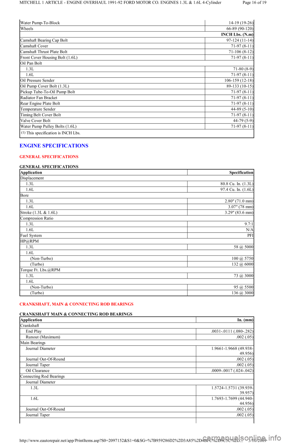
ENGINE SPECIFICATIONS
GENERAL SPECIFICATIONS
GENERAL SPECIFICATIONS
CRANKSHAFT, MAIN & CONNECTING ROD BEARINGS
CRANKSHAFT MAIN & CONNECTING ROD BEARINGS
Water Pump-To-Block14-19 (19-26)
Wheels66-89 (90-120)
INCH Lbs. (N.m)
Camshaft Bearing Cap Bolt97-124 (11-14)
Camshaft Cover71-97 (8-11)
Camshaft Thrust Plate Bolt71-106 (8-12)
Front Cover Housing Bolt (1.6L)71-97 (8-11)
Oil Pan Bolt
1.3L71-80 (8-9)
1.6L71-97 (8-11)
Oil Pressure Sender106-159 (12-18)
Oil Pump Cover Bolt (1.3L)89-133 (10-15)
Pickup Tube-To-Oil Pump Bolt71-97 (8-11)
Radiator Fan Bracket71-97 (8-11)
Rear Engine Plate Bolt71-97 (8-11)
Temperature Sender44-89 (5-10)
Timing Belt Cover Bolt71-97 (8-11)
Valve Cover Bolt44-79 (5-9)
Water Pump Pulley Bolts (1.6L)71-97 (8-11)
(1)This specification is INCH Lbs.
ApplicationSpecification
Displacement
1.3L80.8 Cu. In. (1.3L)
1.6L97.4 Cu. In. (1.6L)
Bore
1.3L2.80" (71.0 mm)
1.6L3.07" (78 mm)
Stroke (1.3L & 1.6L)3.29" (83.6 mm)
Compression Ratio
1.3L9.7:1
1.6LN/A
Fuel SystemPFI
HP@RPM
1.3L58 @ 5000
1.6L
(Non-Turbo)100 @ 5750
(Turbo)132 @ 6000
Torque Ft. Lbs.@RPM
1.3L73 @ 3000
1.6L
(Non-Turbo)95 @ 5500
(Turbo)136 @ 3000
ApplicationIn. (mm)
Crankshaft
End Play.0031-.0111 (.080-.282)
Runout (Maximum).002 (.05)
Main Bearings
Journal Diameter1.9661-1.9668 (49.938-
49.956)
Journal Out-Of-Round.002 (.05)
Journal Taper.002 (.05)
Oil Clearance.0009-.0017 (.024-.042)
Connecting Rod Bearings
Journal Diameter
1.3L1.5724-1.5731 (39.939-
39.957)
1.6L1.7693-1.7699 (44.940-
44.956)
Journal Out-Of-Round.002 (.05)
Journal Taper.002 (.05)
Page 16 of 19 MITCHELL 1 ARTICLE - ENGINE OVERHAUL 1991-92 FORD MOTOR CO. ENGINES 1.3L & 1.6L 4-Cylinder
3/10/2009 http://www.eautorepair.net/app/PrintItems.asp?S0=2097152&S1=0&SG=%7B959286D2%2D3A85%2D4BFC%2D9C5C%2D
...
Page 222 of 454
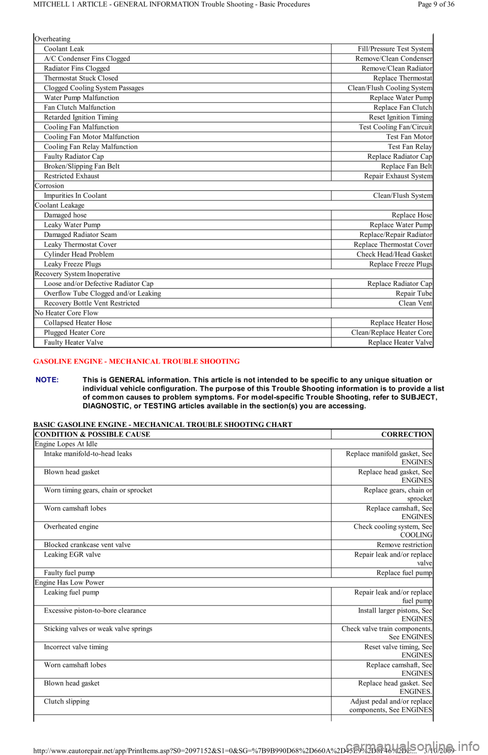
GASOLINE ENGINE - MECHANICAL TROUBLE SHOOTING
BASIC GASOLINE ENGINE - MECHANICAL TROUBLE SHOOTING CHART
Overheating
Coolant LeakFill/Pressure Test System
A/C Condenser Fins CloggedRemove/Clean Condenser
Radiator Fins CloggedRemove/Clean Radiator
Thermostat Stuck ClosedReplace Thermostat
C l o gge d C o o l in g S yst e m P a ssa ge sClean/Flush Cooling System
Water Pump MalfunctionReplace Water Pump
Fan Clutch MalfunctionReplace Fan Clutch
Retarded Ignition TimingReset Ignition Timing
Cooling Fan MalfunctionTest Cooling Fan/Circuit
Cooling Fan Motor MalfunctionTest Fan Motor
Cooling Fan Relay MalfunctionTest Fan Relay
Faulty Radiator CapReplace Radiator Cap
Broken/Slipping Fan BeltReplace Fan Belt
Restricted ExhaustRepair Exhaust System
Corrosion
Impurities In CoolantClean/Flush System
Coolant Leakage
Damaged hoseReplace Hose
Leaky Water PumpReplace Water Pump
Damaged Radiator SeamReplace/Repair Radiator
Leaky Thermostat CoverReplace Thermostat Cover
Cylinder Head ProblemCheck Head/Head Gasket
Leaky Freeze PlugsReplace Freeze Plugs
Recovery System Inoperative
Loose and/or Defective Radiator CapReplace Radiator Cap
Overflow Tube Clogged and/or LeakingRepair Tube
Recovery Bottle Vent RestrictedClean Vent
No Heater Core Flow
Collapsed Heater HoseReplace Heater Hose
Pl u gge d He a t e r C o r eClean/Replace Heater Core
Faulty Heater ValveReplace Heater Valve
NOTE:This is GENERAL inform ation. This article is not intended to be specific to any unique situation or
individual vehicle configuration. T he purpose of this T rouble Shooting inform ation is to provide a list
of com m on causes to problem sym ptom s. For m odel-specific T rouble Shooting, refer to SUBJECT ,
DIAGNOST IC, or T EST ING articles available in the section(s) you are accessing.
CONDITION & POSSIBLE CAUSECORRECTION
Engine Lopes At Idle
In t ake man ifo l d -t o -h ead l eaksReplace manifold gasket, See
ENGINES
Blown head gasketReplace head gasket, See
ENGINES
Worn timing gears, chain or sprocketReplace gears, chain or
sprocket
Worn camshaft lobesReplace camshaft, See
ENGINES
Overheated engineCheck cooling system, See
COOLING
Blocked crankcase vent valveRemove restriction
Le a kin g E GR va l veRepair leak and/or replace
va l ve
Faulty fuel pumpReplace fuel pump
Engine Has Low Power
Leaking fuel pumpRepair leak and/or replace
fu el p u mp
Excessive piston-to-bore clearanceInstall larger pistons, See
ENGINES
Sticking valves or weak valve springsCheck valve train components,
See ENGINES
Incorrect valve timingReset valve timing, See
ENGINES
Worn camshaft lobesReplace camshaft, See
ENGINES
Blown head gasketReplace head gasket. See
ENGINES.
Clutch slippingAdjust pedal and/or replace
components, See ENGINES
Page 9 of 36 MITCHELL 1 ARTICLE - GENERAL INFORMATION Trouble Shooting - Basic Procedures
3/10/2009 http://www.eautorepair.net/app/PrintItems.asp?S0=2097152&S1=0&SG=%7B9B990D68%2D660A%2D45E9%2D8F46%2DE
...
Page 360 of 454
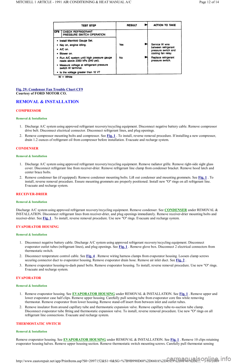
Fig. 29: Condensor Fan Trouble Chart CF9
Courtesy of FORD MOTOR CO.
REMOVAL & INSTALLATION
COMPRESSOR
Removal & Installation
1. Discharge A/C system using approved refrigerant recovery/recycling equipment. Disconnect negative battery cable. Remove compressor
drive belt. Disconnect electrical connector. Disconnect refrigerant lines, and plug openings.
2. Remove compressor mounting bolts and compressor. See Fig. 1
. To install, reverse removal procedure. If installing a new compressor,
drain 1.2 ounces of refrigerant oil from compressor before installation. Evacuate and recharge system.
CONDENSER
Removal & Installation
1. Discharge A/C system using approved refrigerant recovery/recycling equipment. Remove radiator grille. Remove right-side sight glass
cover. Disconnect refrigerant line from receiver-drier. Remove refrigerant line clamp from condenser bracket. Remove hood latch and
center brace bolts.
2. Remove condenser fan (if equipped). Remove condenser mounting bolts. Lift out condenser and mounting grommets. See Fig. 1
. To
install, reverse removal procedure. Ensure mounting grommets are properly positioned. Install new "O" rings on all refrigerant line.
Evacuate and recharge system.
RECEIVER-DRIER
Removal & Installation
Discharge A/C system using approved refrigerant recovery/recycling equipment. Remove condenser. See CONDENSER under REMOVAL &
INSTALLATION. Disconnect refrigerant lines from receiver-drier, and plug openings immediately. Remove receiver-drier mounting bolts and
receiver-drier. See Fig. 1
. To install, reverse removal procedure. Use new "O" rings. Evacuate and recharge system.
EVAPORATOR HOUSING
Removal & Installation
1. Disconnect negative battery cable. Discharge A/C system using approved refrigerant recovery/recycling equipment. Disconnect
evaporator outlet tubes (refrigerant lines), and plug openings. See Fig. 1
. Remove glove box. Disconnect 2 electrical connectors from
thermostatic switch.
2. Disconnect temperature control cable. See Fig. 4
. Remove wiring harness clamps from evaporator housing. Loosen clamp screws
securing connector duct to evaporator housing. Remove evaporator drain hose. Remove air inlet duct. See Fig. 2
.
3. Remove evaporator housing-to-dash panel bolts. Remove evaporator housing. To install, reverse removal procedure. Use new "O" rings.
Evacuate and recharge system.
EVAPORATOR
Removal & Installation
1. Remove evaporator housing. See EVAPORATOR HOUSING under REMOVAL & INSTALLATION. See Fig. 1 . Remove upper and
lower evaporator case half clips. Remove upper housing. Carefully pull sensing tube from evaporator core fins while removing
thermostat. Remove evaporator from lower housing. Remove stand-off insert from between inlet and outlet tubes.
2. Remove insulator from around capillary tube and thermostatic expansion valve. Remove capillary tube-to-suction tube clamp.
Disconnect evaporator tube fitting and thermostatic expansion valve. To install, reverse removal procedure. Use new "O" rings on all
refrigerant line connections. Evacuate and recharge system.
THERMOSTATIC SW ITCH
Removal & Installation
Remove evaporator housing. See EVAPORATOR HOUSING under REMOVAL & INSTALLATION. See Fig. 1. Remove 10 clips retaining
evaporator housing halves. Remove upper housing section. Remove thermostatic switch mounting screws. Carefully pull thermostat sensing
Page 12 of 14 MITCHELL 1 ARTICLE - 1991 AIR CONDITIONING & HEAT MANUAL A/C
3/10/2009 http://www.eautorepair.net/app/PrintItems.asp?S0=2097152&S1=0&SG=%7B9B990D68%2D660A%2D45E9%2D8F46%2DE
...