1991 FORD FESTIVA tow bar
[x] Cancel search: tow barPage 391 of 454

Back To Article
SUSPENSION - FRONT
1991-92 SUSPENSION Front
DESCRIPTION
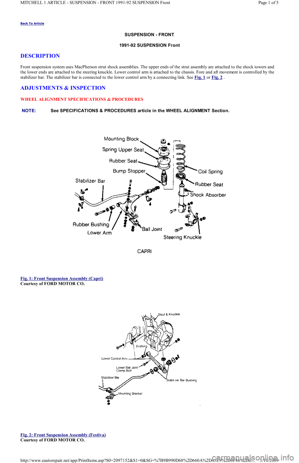
Front suspension system uses MacPherson strut shock assemblies. The upper ends of the strut assembly are attached to the shock towers and
the lower ends are attached to the steering knuckle. Lower control arm is attached to the chassis. Fore and aft movement is controlled by the
stabilizer bar. The stabilizer bar is connected to the lower control arm by a connecting link. See Fig. 1
or Fig. 2 .
ADJUSTMENTS & INSPECTION
WHEEL ALIGNMENT SPECIFICATIONS & PROCEDURES
Fig. 1: Front Suspension Assembly (Capri)
Courtesy of FORD MOTOR CO.
Fig. 2: Front Suspension Assembly (Festiva)
Courtesy of FORD MOTOR CO. NOTE:See SPECIFICAT IONS & PROCEDURES article in the WHEEL ALIGNMENT Section.
Page 1 of 5 MITCHELL 1 ARTICLE - SUSPENSION - FRONT 1991-92 SUSPENSION Front
3/10/2009 http://www.eautorepair.net/app/PrintItems.asp?S0=2097152&S1=0&SG=%7B9B990D68%2D660A%2D45E9%2D8F46%2DE
...
Page 392 of 454

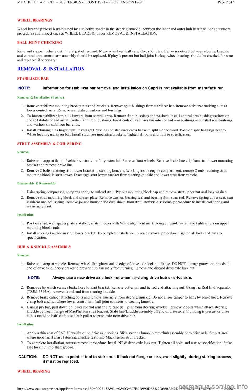
WHEEL BEARINGS
Wheel bearing preload is maintained by a selective spacer in the steering knuckle, between the inner and outer hub bearings. For adjustment
procedures and inspection, see WHEEL BEARING under REMOVAL & INSTALLATION.
BALL JOINT CHECKING
Raise and support vehicle until tire is just off ground. Move wheel vertically and check for play. If play is noticed between steering knuckle
and control arm, control arm assembly should be replaced. If play is present but ball joint is okay, wheel bearings should be checked for wear
and replaced if necessary.
REMOVAL & INSTALLATION
STABILIZER BAR
Removal & Installation (Festiva)
1. Remove stabilizer mounting bracket nuts and brackets. Remove split bushings from stabilizer bar. Remove stabilizer bushing nuts at
lower control arms. Remove rear dished washers and bushings.
2. To loosen stabilizer bar, pull forward from control arms. Remove front bushings and washers. Install control arm bushing washers on
ends of stabilizer and install control arm front bushings. Insert ends of stabilizer bar into control arm bushings and install rear bushings
and washers on stabilizer bar ends.
3. Install retaining nuts finger tight. Install split bushings on stabilizer cross bar with split side forward. Position split bushings next to
White locating marks on bar. Install stabilizer mounting brackets. Tighten all bolts and nuts to specification.
STRUT ASSEMBLY & COIL SPRING
Removal
1. Raise and support front of vehicle so struts are fully extended. Remove front wheels. Remove brake line clip from strut lower mounting
bracket and remove brake line.
2. Remove 2 bolts retaining strut lower bracket to steering knuckle. Working inside engine compartment, remove 2 nuts retaining strut
mounting block in strut tower. Disengage strut lower bracket from steering knuckle and lower strut from vehicle.
Disassembly & Reassembly
1. Using spring compressor, compress spring to unload strut. Pry out mounting block cap and remove strut upper nut and lock washer.
2. Remove strut mounting block and spacer plate. Remove washer, bearing seal and bearing from strut rod. Remove spring upper seat, seat
insulator and coil spring. Remove jounce bumper and dust shield from strut. Reverse disassembly procedure to install coil spring a n d
reassemble strut.
Installation
1. Position strut, with spacer plate installed, in strut tower with White alignment mark facing outward. Install and tighten nuts on upper
mounting block studs.
2. Install steering knuckle in strut lower bracket. To complete installation, reverse removal procedure. Tighten all bolts and nuts to
specification.
HUB & KNUCKLE ASSEMBLY
Removal
1. Raise and support vehicle. Remove wheel. Straighten staked edge of drive axle lock nut flange. DO NOT damage groove or threads in
end of drive axle. Apply brakes to prevent hub assembly from turning. Remove and discard drive axle lock nut.
2. Remove clip which secures brake hose to strut bracket. Remove cotter pin and tie rod end attaching nut. Using Tie Rod End Separator
(T85M-3395A), remove tie rod end from steering knuckle.
3. Remove brake caliper attaching bolts and remove assembly from steering knuckle. Do not allow caliper to hang by brake hose. Remove
clamp bolt and nut where lower control arm ball joint connects to steering knuckle.
4. Using a pry bar, pull down on lower control arm and release ball joint from steering knuckle. Remove 2 bolts which attach steering
knuckle between flanges of MacPherson strut bracket. Slide hub/knuckle assembly off end of drive axle. If binding is present or drive
hub is rusted to half-shaft, use a hub puller to push axle from drive hub.
Installation
1. Apply a thin coat of SAE 30 weight oil to drive axle splines. Slide steering knuckle/rotor/hub assembly onto drive axle. Stop at area
where uppermost arm of steering knuckle seats into MacPherson strut bracket.
2. To complete installation, reverse removal procedure. Install NEW drive axle lock nut. Tighten all bolts and nuts to specification. Stake
axle lock nut into shaft groove.
WHEEL BEARING NOTE:Inform ation for stabilizer bar rem oval and installation on Capri is not available from m anufacturer.
NOTE:Always use a new drive axle lock nut when servicing drive hub or drive axle.
CAUT ION: DO NOT use a pointed tool to stake nut. If lock nut flange cracks, even slightly, during staking process,
it m ust be replaced.
Page 2 of 5 MITCHELL 1 ARTICLE - SUSPENSION - FRONT 1991-92 SUSPENSION Front
3/10/2009 http://www.eautorepair.net/app/PrintItems.asp?S0=2097152&S1=0&SG=%7B9B990D68%2D660A%2D45E9%2D8F46%2DE
...
Page 395 of 454

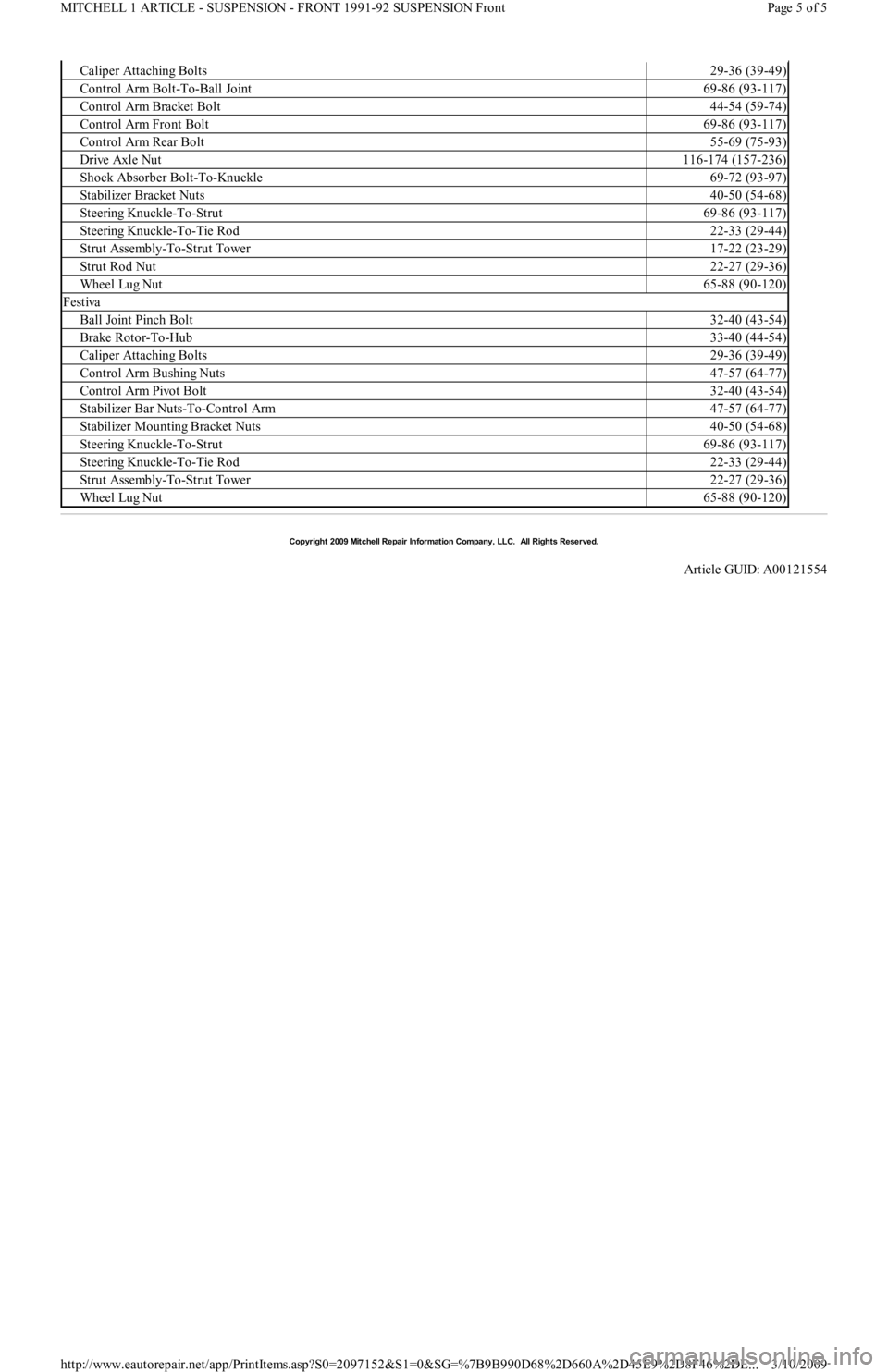
Caliper Attaching Bolts29-36 (39-49)
Control Arm Bolt-To-Ball Joint69-86 (93-117)
Control Arm Bracket Bolt44-54 (59-74)
Control Arm Front Bolt69-86 (93-117)
Control Arm Rear Bolt55-69 (75-93)
Drive Axle Nut116-174 (157-236)
Shock Absorber Bolt-To-Knuckle69-72 (93-97)
Stabilizer Bracket Nuts40-50 (54-68)
Steering Knuckle-To-Strut69-86 (93-117)
Steering Knuckle-To-Tie Rod22-33 (29-44)
Strut Assembly-To-Strut Tower17-22 (23-29)
Strut Rod Nut22-27 (29-36)
Wheel Lug Nut65-88 (90-120)
Festiva
Ball Joint Pinch Bolt32-40 (43-54)
Brake Rotor-To-Hub33-40 (44-54)
Caliper Attaching Bolts29-36 (39-49)
Control Arm Bushing Nuts47-57 (64-77)
Control Arm Pivot Bolt32-40 (43-54)
Stabilizer Bar Nuts-To-Control Arm47-57 (64-77)
Stabilizer Mounting Bracket Nuts40-50 (54-68)
Steering Knuckle-To-Strut69-86 (93-117)
Steering Knuckle-To-Tie Rod22-33 (29-44)
Strut Assembly-To-Strut Tower22-27 (29-36)
Wheel Lug Nut65-88 (90-120)
Copyr ight 2009 Mitchell Repair Information Company, LLC. All Rights Reserved.
Article GUID: A00121554
Page 5 of 5 MITCHELL 1 ARTICLE - SUSPENSION - FRONT 1991-92 SUSPENSION Front
3/10/2009 http://www.eautorepair.net/app/PrintItems.asp?S0=2097152&S1=0&SG=%7B9B990D68%2D660A%2D45E9%2D8F46%2DE
...