1991 FORD FESTIVA key battery
[x] Cancel search: key batteryPage 21 of 454
3. Position Steering Wheel Remover (T67L-3600-A) on steering wheel. Tighten bolt on remover until steering wheel is loose. Remove
steering wheel puller, steering wheel retaining bolt, and steering wheel.
Installation
1. Ensure front wheels are in straight-ahead position. Route clockspring wiring harness through steering wheel opening. Position steering
wheel on steering shaft and align reference marks.
2. Ensure clockspring wire is not pinched when positioning steering wheel. Install new steering wheel retaining bolt and tighten to
specification. See TORQUE SPECIFICATIONS table at end of article. Connect horn and speed control wiring connectors (if equipped)
to steering wheel.
3. Connect air bag module-to-clockspring connector. Install air bag module. Tighten air bag module retaining nuts to specification.
Activate SRS. See SAFETY PRECAUTIONS. Check AIR BAG light to ensure system is functioning properly.
Removal (Festiva)
From back of steering wheel, remove 2 screws securing horn pad. Disconnect horn wire from horn pad and remove pad. Remove steering
wheel nut. Scribe reference mark on steering shaft and steering wheel hub for reassembly. Using Steering Wheel Puller (T67L-3600-A),
remove steering wheel.
Installation
Position steering wheel on steering shaft and align reference marks. Be sure cutouts in rear cover engage turn signal canceling cam. To
complete installation, reverse removal procedure.
COMBINATION SW ITCH
Removal (Capri)
1. Disconnect negative battery cable. Remove lower steering column cover. Remove center access panel and trim cover under steering
column. Remove left side defroster connector tube. Remove steering column upper retaining bolts. Column will pivot downward and
rest on instrument panel brace.
2. Remove 2 switch retaining screws and remove switch. Grasp switch and lever and pull lever out of switch. Disconnect switch electrical
connectors and remove switch.
Installation
Align key with slot and install lever in switch assembly. Position switch on steering column and install retaining screws. To complete
installation, reverse removal procedure.
Removal (Festiva)
1. Disconnect negative battery cable. Remove steering wheel. See STEERING WHEEL & HORN PAD under REMOVAL &
INSTALLATION. Remove 4 screws from upper half of lower steering column cover and remove cover. Remove upper steering column
cover. Remove 5 clips from lower half of lower steering column cover and remove cover.
2. Release wiring harness clip and unplug 4 harness connectors from back of combination switch. From below steering column, loosen
band clamp securing switch hub to steering column jacket. Pull switch assembly from steering column.
Installation
Slide combination switch assembly onto steering column. Make sure switch assembly is seated and level against end of column jacket. To
complete installation, reverse removal procedure.
HEADLIGHT SWITCH
Removal & Installation (Capri)
1. Headlight off/on switch is located on left side of instrument panel bezel. Disconnect negative battery cable. Pull out center storage
compartment. Remove 2 upper screws, 2 lower screws and heater/radio bezel. Pull outward and remove trim covers located on both
sides of steering column.
2. Remove retaining screws and carefully pull instrument panel bezel partially away from dash. Disconnect electrical connector from
headlight switch. Depress tangs on both sides of switch and remove switch from bezel. To install, reverse removal procedure.
IGNITION SWITCH & LOCK CYLINDER
Removal (Capri)
1. Disconnect negative battery cable. Remove lower steering column cover. Remove center access panel and trim cover under steering
column. Remove left side defroster connector tube. Remove steering column upper retaining bolts. Column will pivot downward and
rest on instrument panel brace. steering colum n.
CAUT ION: Rem ove steering wheel carefully to avoid dam aging clockspring wiring, air bag m odule connector, or
accidentally turning clockspring. After steering wheel rem oval, tape clockspring in position to prevent
dam age and keep it from being turned accidentally.
CAUTION: Ensure that no wiring is pinched beneath steering colum n when lowered.
Page 4 of 5 MITCHELL 1 ARTICLE - STEERING COLUMN SWITCHES 1991 ACCESSORIES & SAFETY EQUIPMENT Ford Motor C
...
3/10/2009 http://www.eautorepair.net/app/PrintItems.asp?S0=2097152&S1=0&SG=%7B7DD6473C%2DB5BB%2D4F20%2D9D70%2D
...
Page 22 of 454
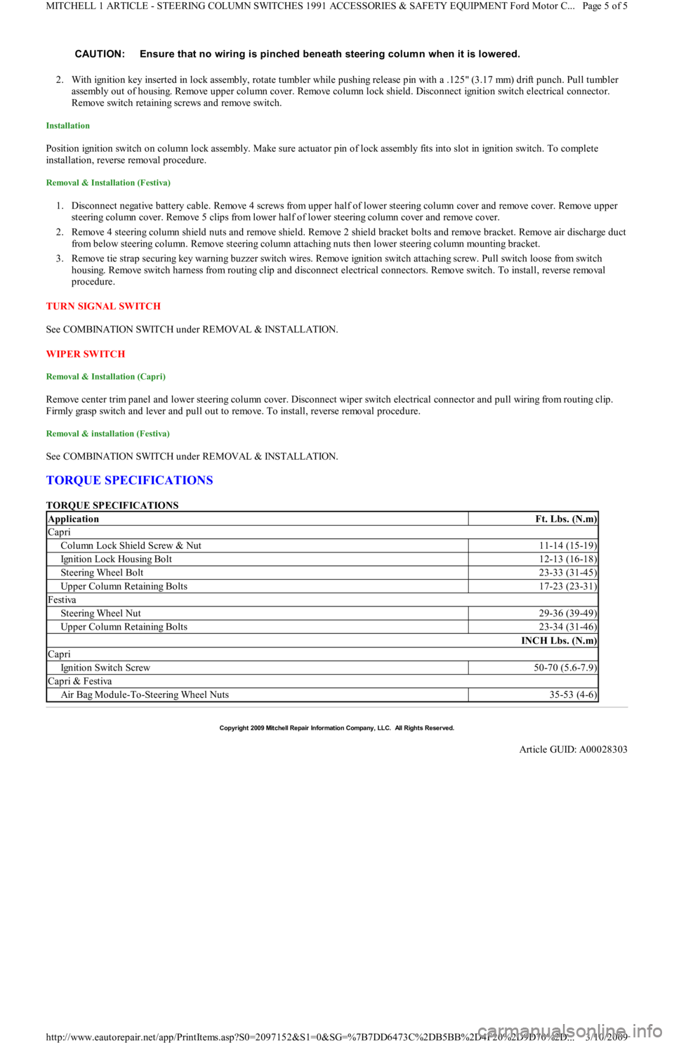
2. With ignition key inserted in lock assembly, rotate tumbler while pushing release pin with a .125" (3.17 mm) drift punch. Pull tumbler
assembly out of housing. Remove upper column cover. Remove column lock shield. Disconnect ignition switch electrical connector.
Remove switch retaining screws and remove switch.
Installation
Position ignition switch on column lock assembly. Make sure actuator pin of lock assembly fits into slot in ignition switch. To complete
installation, reverse removal procedure.
Removal & Installation (Festiva)
1. Disconnect negative battery cable. Remove 4 screws from upper half of lower steering column cover and remove cover. Remove upper
steering column cover. Remove 5 clips from lower half of lower steering column cover and remove cover.
2. Remove 4 steering column shield nuts and remove shield. Remove 2 shield bracket bolts and remove bracket. Remove air discharge duct
from below steering column. Remove steering column attaching nuts then lower steering column mounting bracket.
3. Remove tie strap securing key warning buzzer switch wires. Remove ignition switch attaching screw. Pull switch loose from switch
housing. Remove switch harness from routing clip and disconnect electrical connectors. Remove switch. To install, reverse removal
procedure.
TURN SIGNAL SWITCH
See COMBINATION SWITCH under REMOVAL & INSTALLATION.
WIPER SWITCH
Removal & Installation (Capri)
Remove center trim panel and lower steering column cover. Disconnect wiper switch electrical connector and pull wiring from routing clip.
Firmly grasp switch and lever and pull out to remove. To install, reverse removal procedure.
Removal & installation (Festiva)
See COMBINATION SWITCH under REMOVAL & INSTALLATION.
TORQUE SPECIFICATIONS
TORQUE SPECIFICATIONS CAUTION: Ensure that no wiring is pinched beneath steering colum n when it is lowered.
ApplicationFt. Lbs. (N.m)
Capri
Column Lock Shield Screw & Nut11-14 (15-19)
Ignition Lock Housing Bolt12-13 (16-18)
Steering Wheel Bolt23-33 (31-45)
Upper Column Retaining Bolts17-23 (23-31)
Festiva
Steering Wheel Nut29-36 (39-49)
Upper Column Retaining Bolts23-34 (31-46)
INCH Lbs. (N.m)
Capri
Ign it io n Swit ch Screw50-70 (5.6-7.9)
Capri & Festiva
Air Bag Module-To-Steering Wheel Nuts35-53 (4-6)
Copyr ight 2009 Mitchell Repair Information Company, LLC. All Rights Reserved.
Article GUID: A00028303
Page 5 of 5 MITCHELL 1 ARTICLE - STEERING COLUMN SWITCHES 1991 ACCESSORIES & SAFETY EQUIPMENT Ford Motor C
...
3/10/2009 http://www.eautorepair.net/app/PrintItems.asp?S0=2097152&S1=0&SG=%7B7DD6473C%2DB5BB%2D4F20%2D9D70%2D
...
Page 50 of 454
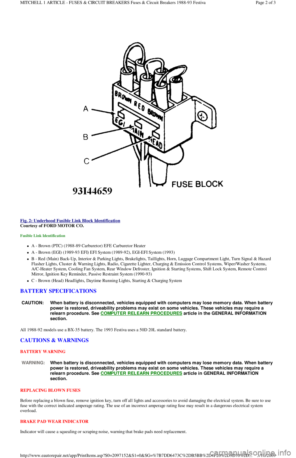
Fig. 2: Underhood Fusible Link Block Identification
Courtesy of FORD MOTOR CO.
Fusible Link Identification
A - Brown (PTC) (1988-89 Carburetor) EFE Carburetor Heater
A - Brown (EGI) (1989-93 EFI) EFI System (1989-92), EGI-EFI System (1993)
B - Red (Main) Back-Up, Interior & Parking Lights, Brakelights, Taillights, Horn, Luggage Compartment Light, Turn Signal & Hazard
F l a sh e r Ligh t s, C l u st e r & Wa r n in g Ligh t s, R a d io , C iga r e t t e Ligh t e r , C h a r gin g & E missio n C o n t r o l S yst e ms, Wip e r / Wa sh e r S yst e ms,
A/C-Heater System, Cooling Fan System, Rear Window Defroster, Ignition & Starting Systems, Shift Lock System, Remote Control
Mirror, Ignition Key Reminder, Passive Restraint System (1990-93)
C - Brown (Head) Headlights, Daytime Running Lights, Starting & Charging System
BATTERY SPECIFICATIONS
All 1988-92 models use a BX-35 battery. The 1993 Festiva uses a 50D 20L standard battery.
CAUTIONS & WARNINGS
BATTERY WARNING
REPLACING BLOWN FUSES
Before replacing a blown fuse, remove ignition key, turn off all lights and accessories to avoid damaging the electrical system. Be sure to use
fuse with the correct indicated amperage rating. The use of an incorrect amperage rating fuse may result in a dangerous electrical system
overload.
BRAKE PAD WEAR INDICATOR
Indicator will cause a squealing or scraping noise, warning that brake pads need replacement.
CAUT ION: When battery is disconnected, vehicles equipped with com puters m ay lose m em ory data. When battery
power is restored, driveability problem s m ay exist on som e vehicles. T hese vehicles m ay require a
relearn procedure. See COMPUTER RELEARN PROCEDURES
article in the GENERAL INFORMAT ION
section.
WARNING:When battery is disconnected, vehicles equipped with com puters m ay lose m em ory data. When battery
power is restored, driveability problem s m ay exist on som e vehicles. T hese vehicles m ay require a
relearn procedure. See COMPUTER RELEARN PROCEDURES
article in GENERAL INFORMAT ION
section.
Page 2 of 3 MITCHELL 1 ARTICLE - FUSES & CIRCUIT BREAKERS Fuses & Circuit Breakers 1988-93 Festiva
3/10/2009 http://www.eautorepair.net/app/PrintItems.asp?S0=2097152&S1=0&SG=%7B7DD6473C%2DB5BB%2D4F20%2D9D70%2D
...
Page 66 of 454

Autolamp Control RelayHeadlight Systems; Daytime Running Lights
Automatic Shutdown (ASD) RelayEngine Performance; Generators & Regulators
Autostick SwitchEngine Performance
Auxiliary Battery RelayGenerators & Regulators
Back-Up LightsBack-Up Lights; Exterior Lights
Barometric (BARO) Pressure SensorEngine Performance
BatteryPower Distribution
Battery Temperature SensorEngine Performance
Body Control ModuleBody Control Computer; Anti-Theft System; Daytime Running
Lights; Engine Performance; Headlight Systems; Warning Systems
Boost Control SolenoidEngine Performance
Boost SensorEngine Performance
Brake Fluid Level SwitchAnalog Instrument Panels
Brake On/Off (BOO) SwitchCruise Control Systems; Engine Performance; Shift Interlock
Systems
Buzzer ModuleWarning Systems
Camshaft Position (CMP) SensorEngine Performance
Central Control ModuleAnti-Theft System
ClockspringAir Bag Restraint System; Cruise Control Systems; Steering
Column Switches
Clutch Pedal Position SwitchStarters
Clutch Start SwitchStarters
Combination MeterAnalog Instrument Panels
Constant Control Relay Module (CCRM)Engine Performance; Electric Cooling Fans
Convenience CenterPower Distribution; Illumination/Interior Lights
Convertible Top MotorPower Convertible Top
Convertible Top SwitchPower Convertible Top
Crankshaft Position (CKP) SensorEngine Performance
Cruise Control ModuleCruise Control Systems
Cruise Control SwitchCruise Control Systems
Condenser Fan Relay(s)Electric Cooling Fans
Data Link Connector (DLC)Engine Performance
Da yt ime R u n n in g Ligh t s M o d u l eDaytime Running Lights; Exterior Lights
Defogger RelayRear Window Defogger
Diagnostic Energy Reserve Module (DERM)Air Bag Restraint System
Discriminating Sensor (Air Bag)Air Bag Restraint System
DistributorEngine Performance
Door Lock ActuatorsPower Door Locks; Remote Keyless Entry
Door Lock Relay(s)Power Door Locks
Electrochromic MirrorPower Mirrors
Electronic Level Control (ELC) Height SensorElectronic Suspension
Electronic Level Control (ELC) ModuleElectronic Suspension
Engine Coolant Temperature (ECT) Sending UnitAnalog Instrument Panels
Engine Coolant Temperature (ECT) SensorEngine Performance
Engine Control ModuleEngine Performance; Generators & Regulators; Starters
ETACS ECUWarning Systems; Power Windows; Remote Keyless Entry
Evaporative (EVAP) Emissions CanisterEngine Performance
EVAP Canister Purge SolenoidEngine Performance
EVAP Canister Vent SolenoidEngine Performance
Exhaust Gas Recirculation (EGR) ValveEngine Performance
Fuel Tank Vacuum SensorEngine Performance
F o g Ligh t sHeadlight Systems; Daytime Running Lights
F o g Ligh t R e l a yHeadlight Systems; Daytime Running Lights
Fuel Door Release SolenoidPower Fuel Door Release
Fuel Gauge Sending UnitAnalog Instrument Panels
Fuel InjectorsEngine Performance
Fuel PumpEngine Performance
Fuel Pump RelayEngine Performance; Power Distribution
Fuse/Relay BlockPower Distribution
Fusible LinksPower Distribution; Generators & Regulators; Starters
GeneratorGenerators & Regulators; Engine Performance; Power Distribution
Generic Electronic Module (GEM)Body Control Modules; Electronic Suspension
Glow Plug RelayEngine Performance
Glow PlugsEngine Performance
GroundsGround Distribution
Headlight Door ModuleHeadlight Doors
Headlight RelayHeadlight Systems; Daytime Running Lights
HeadlightsHeadlight Systems; Daytime Running Lights
Heated Oxygen Sensor(s) (HO2S)Engine Performance
Heated Windshield Control ModuleHeated Windshields
Page 4 of 6 MITCHELL 1 ARTICLE - GENERAL INFORMATION Using Mitchell1's Wiring Diagrams
3/10/2009 http://www.eautorepair.net/app/PrintItems.asp?S0=2097152&S1=0&SG=%7B959286D2%2D3A85%2D4BFC%2D9C5C%2D
...
Page 69 of 454
Back To Article
WIRING DIAGRAMS
1991 WIRING DIAGRAMS Ford Motor Co.
IDENTIFICATION
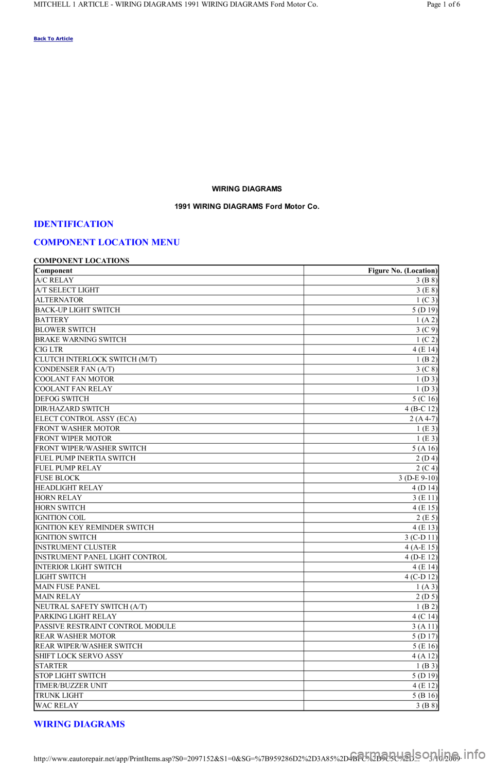
COMPONENT LOCATION MENU
COMPONENT LOCATIONS
WIRING DIAGRAMS
ComponentFigure No. (Location)
A/C RELAY3 (B 8)
A/T SELECT LIGHT3 (E 8)
ALTERNATOR1 (C 3)
BACK-UP LIGHT SWITCH5 (D 19)
BATTERY1 (A 2)
BLOWER SWITCH3 (C 9)
BRAKE WARNING SWITCH1 (C 2)
CIG LTR4 (E 14)
CLUTCH INTERLOCK SWITCH (M/T)1 (B 2)
CONDENSER FAN (A/T)3 (C 8)
COOLANT FAN MOTOR1 (D 3)
COOLANT FAN RELAY1 (D 3)
DEFOG SWITCH5 (C 16)
DIR/HAZARD SWITCH4 (B-C 12)
ELECT CONTROL ASSY (ECA)2 (A 4-7)
FRONT WASHER MOTOR1 (E 3)
FRONT WIPER MOTOR1 (E 3)
FRONT WIPER/WASHER SWITCH5 (A 16)
FUEL PUMP INERTIA SWITCH2 (D 4)
FUEL PUMP RELAY2 (C 4)
FUSE BLOCK3 (D-E 9-10)
HEADLIGHT RELAY4 (D 14)
HORN RELAY3 (E 11)
HORN SWITCH4 (E 15)
IGNITION COIL2 (E 5)
IGNITION KEY REMINDER SWITCH4 (E 13)
IGNITION SWITCH3 (C-D 11)
INSTRUMENT CLUSTER4 (A-E 15)
INSTRUMENT PANEL LIGHT CONTROL4 (D-E 12)
INTERIOR LIGHT SWITCH4 (E 14)
LIGHT SWITCH4 (C-D 12)
MAIN FUSE PANEL1 (A 3)
MAIN RELAY2 (D 5)
NEUTRAL SAFETY SWITCH (A/T)1 (B 2)
PARKING LIGHT RELAY4 (C 14)
PASSIVE RESTRAINT CONTROL MODULE3 (A 11)
REAR WASHER MOTOR5 (D 17)
REAR WIPER/WASHER SWITCH5 (E 16)
SHIFT LOCK SERVO ASSY4 (A 12)
STARTER1 (B 3)
STOP LIGHT SWITCH5 (D 19)
TIMER/BUZZER UNIT4 (E 12)
TRUNK LIGHT5 (B 16)
WAC RELAY3 (B 8)
Page 1 of 6 MITCHELL 1 ARTICLE - WIRING DIAGRAMS 1991 WIRING DIAGRAMS Ford Motor Co.
3/10/2009 http://www.eautorepair.net/app/PrintItems.asp?S0=2097152&S1=0&SG=%7B959286D2%2D3A85%2D4BFC%2D9C5C%2D
...
Page 171 of 454
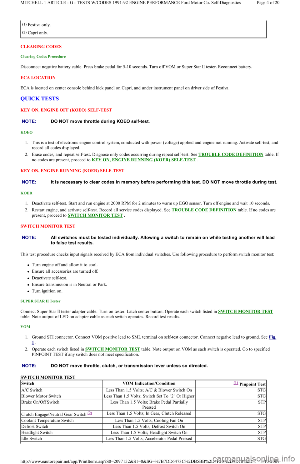
CLEARING CODES
Clearing Codes Procedure
Disconnect negative battery cable. Press brake pedal for 5-10 seconds. Turn off VOM or Super Star II tester. Reconnect battery.
ECA LOCATION
ECA is located on center console behind kick panel on Capri, and under instrument panel on driver side of Festiva.
QUICK TESTS
KEY ON, ENGINE OFF (KOEO) SELF-TEST
KOEO
1. This is a test of electronic engine control system, conducted with power (voltage) applied and engine not running. Activate self-test, and
record all codes displayed.
2. Erase codes, and repeat self-test. Diagnose only codes occurring during repeat self-test. See TROUBLE CODE DEFINITION
table. If
no codes are present, proceed to KEY ON, ENGINE RUNNING (KOER) SELF
-TEST .
KEY ON, ENGINE RUNNING (KOER) SELF-TEST
KOER
1. Deactivate self-test. Start and run engine at 2000 RPM for 2 minutes to warm up EGO sensor. Turn off engine and wait 10 seconds.
2. Restart engine, and activate self-test. Record all service codes displayed. See TROUBLE CODE DEFINITION
table. If no codes are
present, proceed to SWITCH MONITOR TEST
.
SWITCH MONITOR TEST
This test procedure checks input signals received by ECA from individual switches. Use following procedure to perform switch monitor test:
Turn engine off and allow it to cool.
Ensure all accessories are turned off.
Deactivate self-test.
Ensure transmission is in Neutral or Park.
Turn ignition on.
SUPER STAR II Tester
Connect Super Star II tester adapter cable. Turn on tester. Latch center button. Operate each switch listed in SWITCH MONITOR TEST
table. Note output of LED on adapter cable as each switch operates. Record test results.
VOM
1. Ground STI connector. Connect VOM positive lead to SML terminal on self-test connector. Connect negative lead to ground. See Fig.
1 .
2. Operate each switch listed in SWITCH MONITOR TEST
table. Note output on VOM as each switch is operated. Go to specified
PINPOINT TEST if any switch does not meet specification.
SWITCH MONITOR TEST
(1)Festiva only.
(2)Capri only.
NOTE:DO NOT m ove throttle during KOEO self-test.
NOTE:It is necessary to clear codes in m em ory before perform ing this test. DO NOT m ove throttle during test.
NOTE:All switches m ust be tested individually. Allowing a switch to rem ain on while testing another will lead
to false test results.
NOTE:DO NOT m ove throttle, clutch, or transm ission lever unless so directed.
SwitchVOM Indication/Condition(1) Pinpoint Test
A/C SwitchLess Than 1.5 Volts; A/C & Blower Switch OnSTG
Blower Motor SwitchLess Than 1.5 Volts; Switch Set To "2" Or HigherSTG
Brake On/Off SwitchLess Than 1.5 Volts; Brake Pedal Partially
PressedSTP
Clutch Engage/Neutral Gear Switch (2) Less Than 1.5 Volts; In Gear, Clutch ReleasedSTG
Coolant Temperature SwitchLess Than 1.5 Volts; Cooling Fan OnSTP
Defrost SwitchLess Than 1.5 Volts; Defrost Switch OnSTP
Headlight SwitchLess Than 1.5 Volts; Headlight Switch OnSTP
Id l e Swit chLess Than 1.5 Volts; Accelerator Pedal PressedSTG
Page 4 of 20 MITCHELL 1 ARTICLE - G - TESTS W/CODES 1991-92 ENGINE PERFORMANCE Ford Motor Co. Self-Diagnostics
3/10/2009 http://www.eautorepair.net/app/PrintItems.asp?S0=2097152&S1=0&SG=%7B7DD6473C%2DB5BB%2D4F20%2D9D70%2D
...
Page 219 of 454
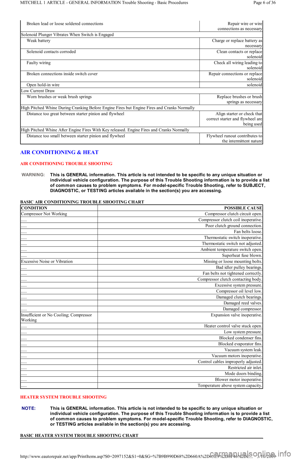
AIR CONDITIONING & HEAT
AIR CONDITIONING TROUBLE SHOOTING
BASIC AIR CONDITIONING TROUBLE SHOOTING CHART
HEATER SYSTEM TROUBLE SHOOTING
BASIC HEATER SYSTEM TROUBLE SHOOTING CHART
Broken lead or loose soldered connectionsRepair wire or wire
connections as necessary
Solenoid Plunger Vibrates When Switch is Engaged
Weak batteryCharge or replace battery as
necessary
Solenoid contacts corrodedClean contacts or replace
solenoid
Faulty wiringCheck all wiring leading to
solenoid
Broken connections inside switch coverRepair connections or replace
solenoid
Open hold-in wiresolenoid
Low Current Draw
Worn brushes or weak brush springsReplace brushes or brush
springs as necessary
High Pitched Whine During Cranking Before Engine Fires but Engine Fires and Cranks Normally
Distance too great between starter pinion and flywheelAlign starter or check that
correct starter and flywheel are
being used
High Pitched Whine After Engine Fires With Key released. Engine Fires and Cranks Normally
Distance too small between starter pinion and flywheelFlywheel runout contributes to
the intermittent nature
WARNING:This is GENERAL inform ation. This article is not intended to be specific to any unique situation or
individual vehicle configuration. T he purpose of this T rouble Shooting inform ation is to provide a list
of com m on causes to problem sym ptom s. For m odel-specific T rouble Shooting, refer to SUBJECT ,
DIAGNOST IC, or T EST ING articles available in the section(s) you are accessing.
CONDITIONPOSSIBLE CAUSE
Compressor Not WorkingCompressor clutch circuit open.
.....Compressor clutch coil inoperative.
.....Poor clutch ground connection.
.....Fan belts loose.
.....Thermostatic switch inoperative.
.....Thermostatic switch not adjusted.
.....Ambient temperature switch open.
.....Superheat fuse blown.
Excessive Noise or VibrationMissing or loose mounting bolts.
.....Bad idler pulley bearings.
.....Fan belts not tightened correctly.
.....Compressor clutch contacting body.
.....Excessive system pressure.
.....Compressor oil level low.
.....Damaged clutch bearings.
.....Damaged reed valves.
.....Damaged compressor.
In su fficien t o r No Co o l in g; Co mp resso r
WorkingExpansion valve inoperative.
.....Heater control valve stuck open.
.....Low system pressure.
.....Blocked condenser fins.
.....Blocked evaporator fins.
.....Vacuum system leak.
.....Vacuum motors inoperative.
.....Control cables improperly adjusted.
.....Restricted air inlet.
.....Mode doors binding.
.....Blower motor inoperative.
.....Temperature above system capacity.
NOTE:This is GENERAL inform ation. This article is not intended to be specific to any unique situation or
individual vehicle configuration. T he purpose of this T rouble Shooting inform ation is to provide a list
of com m on causes to problem sym ptom s. For m odel-specific T rouble Shooting, refer to DIAGNOST IC,
or T EST ING articles available in the section(s) you are accessing.
Page 6 of 36 MITCHELL 1 ARTICLE - GENERAL INFORMATION Trouble Shooting - Basic Procedures
3/10/2009 http://www.eautorepair.net/app/PrintItems.asp?S0=2097152&S1=0&SG=%7B9B990D68%2D660A%2D45E9%2D8F46%2DE
...
Page 234 of 454
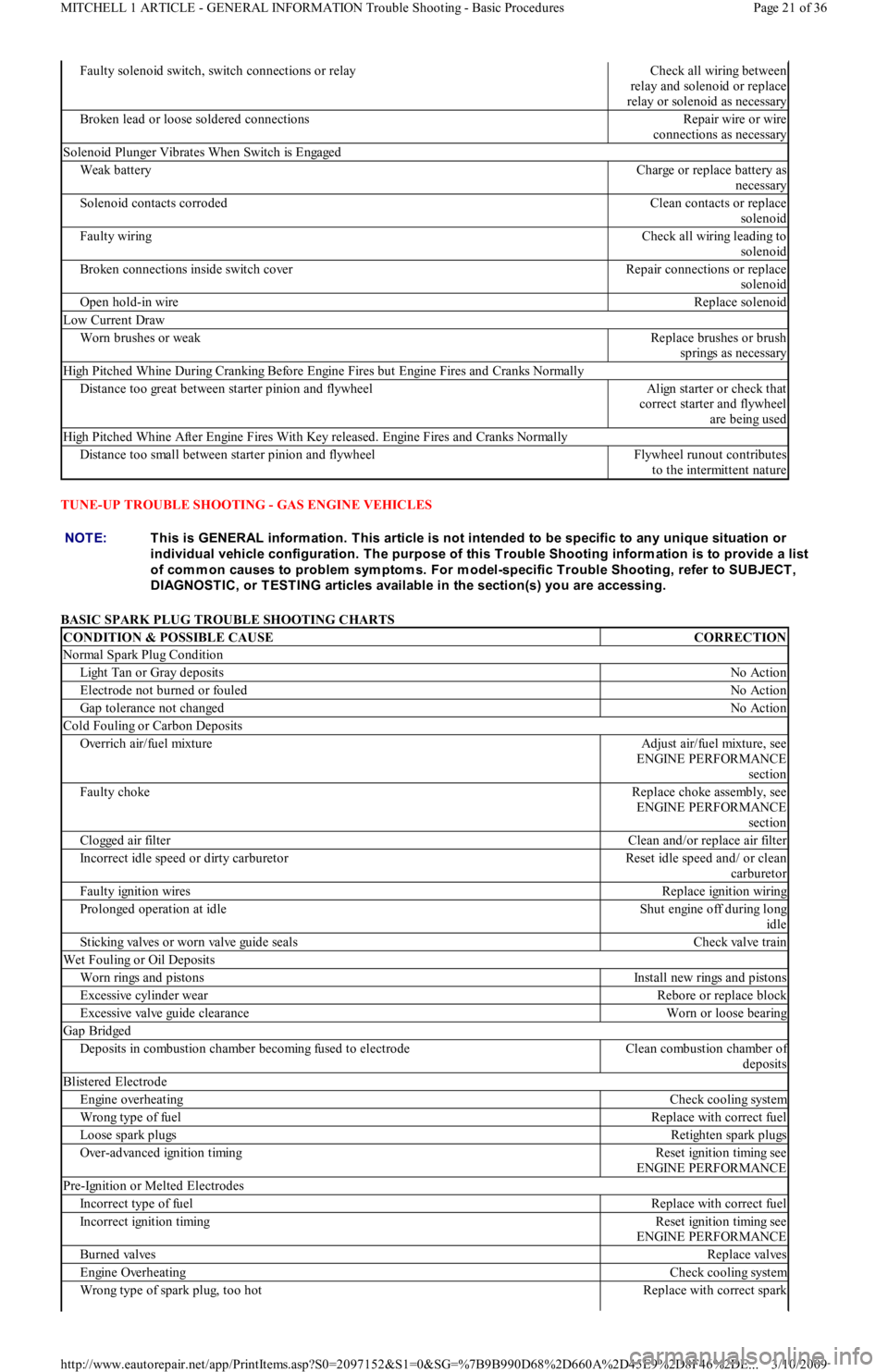
TUNE-UP TROUBLE SHOOTING - GAS ENGINE VEHICLES
BASIC SPARK PLUG TROUBLE SHOOTING CHARTS
Faulty solenoid switch, switch connections or relayCheck all wiring between
relay and solenoid or replace
relay or solenoid as necessary
Broken lead or loose soldered connectionsRepair wire or wire
connections as necessary
Solenoid Plunger Vibrates When Switch is Engaged
Weak batteryCharge or replace battery as
necessary
Solenoid contacts corrodedClean contacts or replace
solenoid
Faulty wiringCheck all wiring leading to
solenoid
Broken connections inside switch coverRepair connections or replace
solenoid
Open hold-in wireReplace solenoid
Low Current Draw
Worn brushes or weakReplace brushes or brush
springs as necessary
High Pitched Whine During Cranking Before Engine Fires but Engine Fires and Cranks Normally
Distance too great between starter pinion and flywheelAlign starter or check that
correct starter and flywheel
are being used
High Pitched Whine After Engine Fires With Key released. Engine Fires and Cranks Normally
Distance too small between starter pinion and flywheelFlywheel runout contributes
to the intermittent nature
NOTE:This is GENERAL inform ation. This article is not intended to be specific to any unique situation or
individual vehicle configuration. T he purpose of this T rouble Shooting inform ation is to provide a list
of com m on causes to problem sym ptom s. For m odel-specific T rouble Shooting, refer to SUBJECT ,
DIAGNOST IC, or T EST ING articles available in the section(s) you are accessing.
CONDITION & POSSIBLE CAUSECORRECTION
Normal Spark Plug Condition
Light Tan or Gray depositsNo Action
Electrode not burned or fouledNo Action
Gap tolerance not changedNo Action
Cold Fouling or Carbon Deposits
Overrich air/fuel mixtureAdjust air/fuel mixture, see
ENGINE PERFORMANCE
section
Faulty chokeReplace choke assembly, see
ENGINE PERFORMANCE
section
Clogged air filterClean and/or replace air filter
Incorrect idle speed or dirty carburetorReset idle speed and/ or clean
carburetor
Faulty ignition wiresReplace ignition wiring
Prolonged operation at idleShut engine off during long
idle
Sticking valves or worn valve guide sealsCheck valve train
Wet Fouling or Oil Deposits
Worn rings and pistonsInstall new rings and pistons
Excessive cylinder wearRebore or replace block
Excessive valve guide clearanceWorn or loose bearing
Gap Bridged
Deposits in combustion chamber becoming fused to electrodeClean combustion chamber of
deposits
Blistered Electrode
Engine overheatingCheck cooling system
Wrong type of fuelReplace with correct fuel
Loose spark plugsRetighten spark plugs
Over-advanced ignition timingReset ignition timing see
ENGINE PERFORMANCE
Pre-Ignition or Melted Electrodes
Incorrect type of fuelReplace with correct fuel
Incorrect ignition timingReset ignition timing see
ENGINE PERFORMANCE
Burned valvesReplace valves
Engine OverheatingCheck cooling system
Wrong type of spark plug, too hotReplace with correct spark
Page 21 of 36 MITCHELL 1 ARTICLE - GENERAL INFORMATION Trouble Shooting - Basic Procedures
3/10/2009 http://www.eautorepair.net/app/PrintItems.asp?S0=2097152&S1=0&SG=%7B9B990D68%2D660A%2D45E9%2D8F46%2DE
...