1991 FORD FESTIVA alternator belt
[x] Cancel search: alternator beltPage 43 of 454
Back To Article
ALTERNATOR & REGULATOR
1991 ELECT RICAL Alternators & Regulators
DESCRIPTION
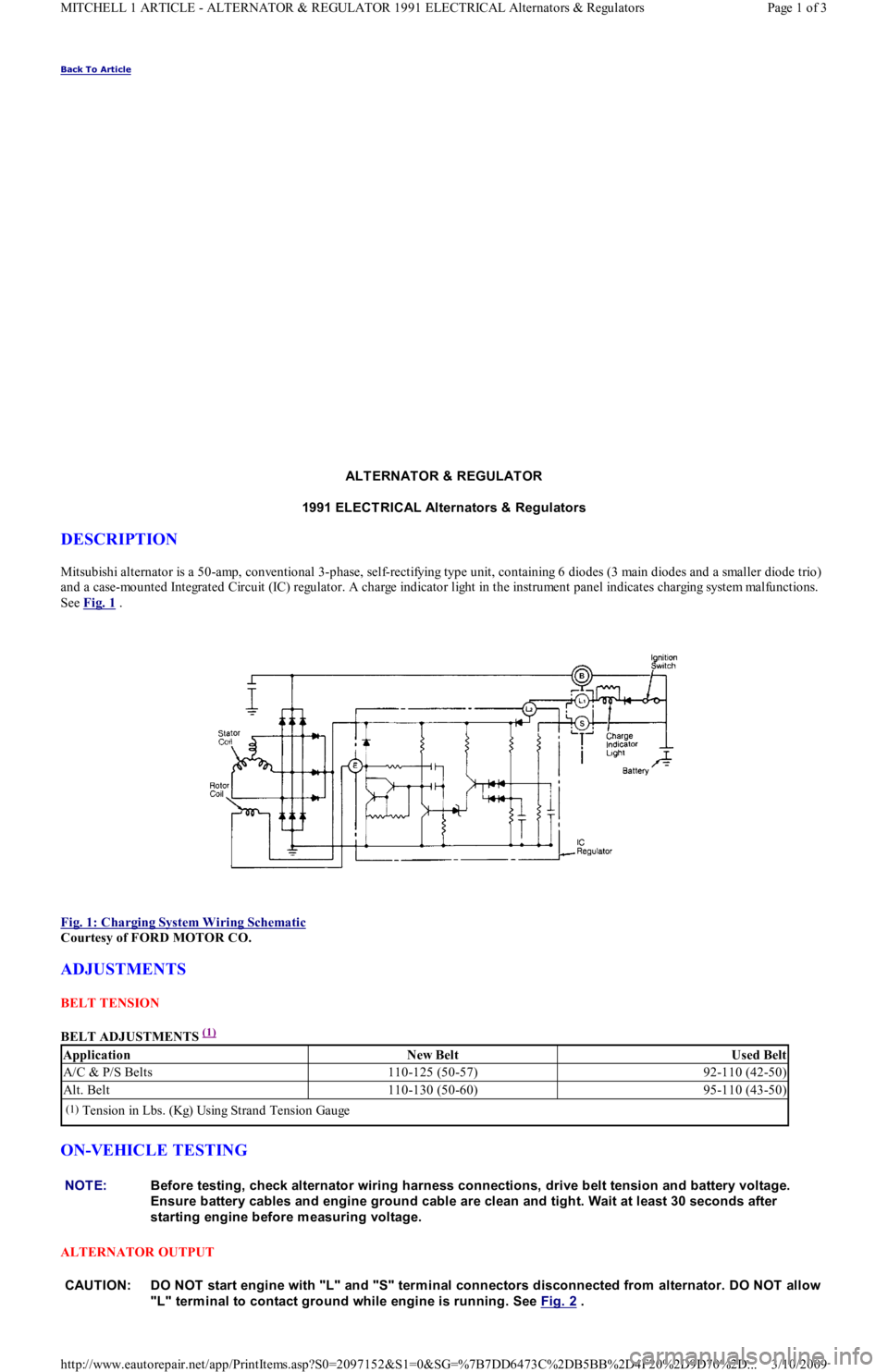
Mitsubishi alternator is a 50-amp, conventional 3-phase, self-rectifying type unit, containing 6 diodes (3 main diodes and a smaller diode trio)
and a case-mounted Integrated Circuit (IC) regulator. A charge indicator light in the instrument panel indicates charging system mal fu n ct io n s.
See Fig. 1
.
Fig. 1: Charging System Wiring Schematic
Courtesy of FORD MOTOR CO.
ADJUSTMENTS
BELT TENSION
BELT ADJUSTMENTS
(1)
ON-VEHICLE TESTING
ALTERNATOR OUTPUT
ApplicationNew BeltUsed Belt
A/C & P/S Belts110-125 (50-57)92-110 (42-50)
Alt. Belt110-130 (50-60)95-110 (43-50)
(1)Tension in Lbs. (Kg) Using Strand Tension Gauge
NOTE:Before testing, check alternator wiring harness connections, drive belt tension and battery voltage.
Ensure battery cables and engine ground cable are clean and tight. Wait at least 30 seconds after
starting engine before m easuring voltage.
CAUT ION: DO NOT start engine with "L" and "S" term inal connectors disconnected from alternator. DO NOT allow
"L" term inal to contact ground while engine is running. See Fig. 2
.
Page 1 of 3 MITCHELL 1 ARTICLE - ALTERNATOR & REGULATOR 1991 ELECTRICAL Alternators & Regulators
3/10/2009 http://www.eautorepair.net/app/PrintItems.asp?S0=2097152&S1=0&SG=%7B7DD6473C%2DB5BB%2D4F20%2D9D70%2D
...
Page 75 of 454
Back To Article
DRIVE BELT ROUTING
1991-92 ENGINE COOLING BELT ROUT ING
BELT ADJUSTMENT
Tensioners may be used to automatically adjust belt tension to specification. Check belt for fraying. If fraying exists, ensure both belt and
tensioner are properly aligned. See Fig. 1
. Tensioners may contain a belt-wear indicator. See Fig. 2 . If tensioner reaches travel limit, as
indicated by marks on tensioner, replace belt. Ensure serpentine belts are properly installed. See Fig. 3
-Fig. 7 . On models without
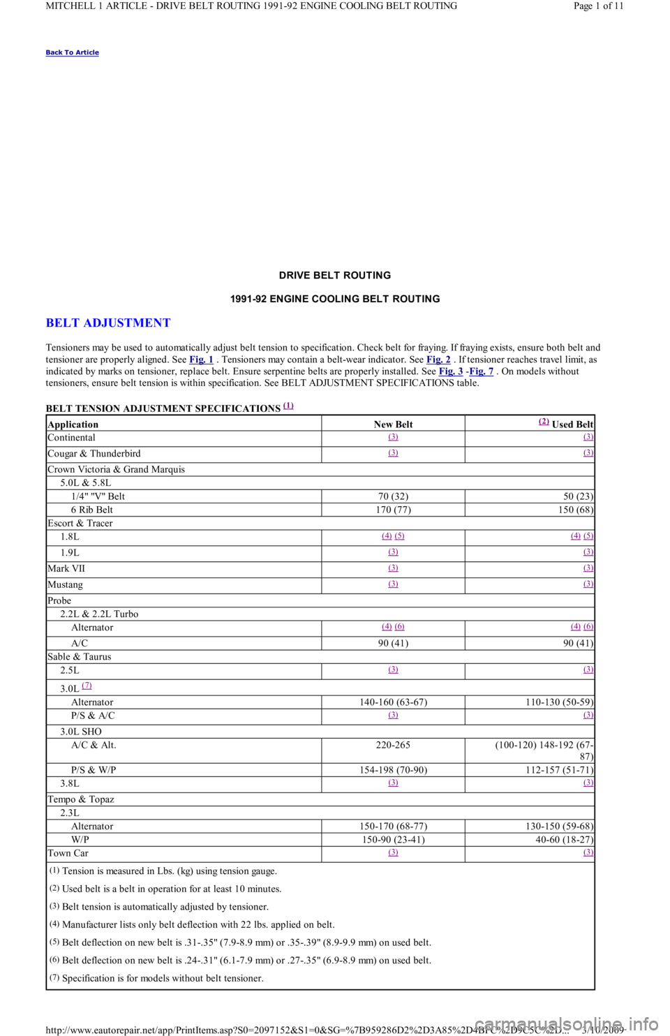
tensioners, ensure belt tension is within specification. See BELT ADJUSTMENT SPECIFICATIONS table.
BELT TENSION ADJUSTMENT SPECIFICATIONS
(1)
ApplicationNew Belt(2) Used Belt
Continental(3) (3)
Cougar & Thunderbird(3) (3)
Crown Victoria & Grand Marquis
5.0L & 5.8L
1/4" "V" Belt70 (32)50 (23)
6 Rib Belt170 (77)150 (68)
Escort & Tracer
1.8L(4) (5) (4) (5)
1.9L(3) (3)
Mark VII(3) (3)
Mustang(3) (3)
Probe
2.2L & 2.2L Turbo
Alternator(4) (6) (4) (6)
A/C90 (41)90 (41)
Sable & Taurus
2.5L(3) (3)
3.0L (7)
Alternator140-160 (63-67)110-130 (50-59)
P/S & A/C(3) (3)
3.0L SHO
A/C & Alt.220-265(100-120) 148-192 (67-
87)
P/S & W/P154-198 (70-90)112-157 (51-71)
3.8L(3) (3)
Tempo & Topaz
2.3L
Alternator150-170 (68-77)130-150 (59-68)
W/P150-90 (23-41)40-60 (18-27)
Town Car(3) (3)
(1)Tension is measured in Lbs. (kg) using tension gauge.
(2)Used belt is a belt in operation for at least 10 minutes.
(3)Belt tension is automatically adjusted by tensioner.
(4)Manufacturer lists only belt deflection with 22 lbs. applied on belt.
(5)Belt deflection on new belt is .31-.35" (7.9-8.9 mm) or .35-.39" (8.9-9.9 mm) on used belt.
(6)Belt deflection on new belt is .24-.31" (6.1-7.9 mm) or .27-.35" (6.9-8.9 mm) on used belt.
(7)Specification is for models without belt tensioner.
Page 1 of 11 MITCHELL 1 ARTICLE - DRIVE BELT ROUTING 1991-92 ENGINE COOLING BELT ROUTING
3/10/2009 http://www.eautorepair.net/app/PrintItems.asp?S0=2097152&S1=0&SG=%7B959286D2%2D3A85%2D4BFC%2D9C5C%2D
...
Page 90 of 454
Back To Article
DRIVE BELT ROUTING
1991-92 ENGINE COOLING BELT ROUT ING
BELT ADJUSTMENT
Tensioners may be used to automatically adjust belt tension to specification. Check belt for fraying. If fraying exists, ensure both belt and
tensioner are properly aligned. See Fig. 1
. Tensioners may contain a belt-wear indicator. See Fig. 2 . If tensioner reaches travel limit, as
indicated by marks on tensioner, replace belt. Ensure serpentine belts are properly installed. See Fig. 3
-Fig. 7 . On models without
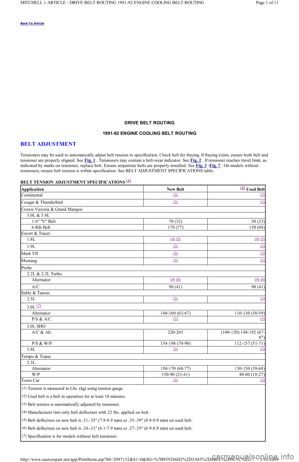
tensioners, ensure belt tension is within specification. See BELT ADJUSTMENT SPECIFICATIONS table.
BELT TENSION ADJUSTMENT SPECIFICATIONS
(1)
ApplicationNew Belt(2) Used Belt
Continental(3) (3)
Cougar & Thunderbird(3) (3)
Crown Victoria & Grand Marquis
5.0L & 5.8L
1/4" "V" Belt70 (32)50 (23)
6 Rib Belt170 (77)150 (68)
Escort & Tracer
1.8L(4) (5) (4) (5)
1.9L(3) (3)
Mark VII(3) (3)
Mustang(3) (3)
Probe
2.2L & 2.2L Turbo
Alternator(4) (6) (4) (6)
A/C90 (41)90 (41)
Sable & Taurus
2.5L(3) (3)
3.0L (7)
Alternator140-160 (63-67)110-130 (50-59)
P/S & A/C(3) (3)
3.0L SHO
A/C & Alt.220-265(100-120) 148-192 (67-
87)
P/S & W/P154-198 (70-90)112-157 (51-71)
3.8L(3) (3)
Tempo & Topaz
2.3L
Alternator150-170 (68-77)130-150 (59-68)
W/P150-90 (23-41)40-60 (18-27)
Town Car(3) (3)
(1)Tension is measured in Lbs. (kg) using tension gauge.
(2)Used belt is a belt in operation for at least 10 minutes.
(3)Belt tension is automatically adjusted by tensioner.
(4)Manufacturer lists only belt deflection with 22 lbs. applied on belt.
(5)Belt deflection on new belt is .31-.35" (7.9-8.9 mm) or .35-.39" (8.9-9.9 mm) on used belt.
(6)Belt deflection on new belt is .24-.31" (6.1-7.9 mm) or .27-.35" (6.9-8.9 mm) on used belt.
(7)Specification is for models without belt tensioner.
Page 1 of 11 MITCHELL 1 ARTICLE - DRIVE BELT ROUTING 1991-92 ENGINE COOLING BELT ROUTING
3/10/2009 http://www.eautorepair.net/app/PrintItems.asp?S0=2097152&S1=0&SG=%7B959286D2%2D3A85%2D4BFC%2D9C5C%2D
...
Page 102 of 454

levels to proper level.
Removal (1.6L & 1.6L Turbo)
1. Relieve fuel pressure and discharge air conditioning system (if equipped). See FUEL PRESSURE RELEASE under REMOVAL &
INSTALLATION. Disconnect and remove battery, battery tray and battery tray support bracket.
2. Release wiring harness retaining straps from battery support tray. Disconnect windshield washer supply hose between fluid reservoir and
hood. Mark hinge locations and remove hood.
3. Disconnect intake air tube and wiring to ignition coil and vane airflow meter. Remove air cleaner/vane airflow meter assembly. Remove
air cleaner assembly support brackets. Disconnect intercooler hoses from turbocharger (if equipped).
4. Drain engine coolant and remove radiator. Disconnect accelerator cable, and remove retaining bracket from cam cover. Position cable to
one side.
5. Disconnect and plug fuel lines at fuel filter and pressure regulator. Disconnect power brake booster manifold vacuum hose from
manifold. Disconnect heater hoses at heater core tubes. Label and remove vacuum hoses located at throttle body.
6. For manual transaxle turbocharged vehicles, disconnect clutch cable and remove support bracket and cable from transmission. On non-
turbo vehicles, disconnect clutch slave hydraulic line. For automatic transaxle, remove transaxle cooler lines.
7. Disconnect starter wiring at starter. Remove harness from locating strap on bracket. Disconnect alternator wiring. Disconnect wiring
from engine coolant sensors located on rear of engine block. Remove ground connection at bracket on thermostat cover. Disconnect O2
sensor wire, main wiring harness connector, TPS connector (turbocharged only), knock sensor connector, distributor wiring and
transaxle wiring. Disconnect ground wire and strap at front of engine, and reinstall lifting eye.
8. Remove engine oil dipstick and retaining clip. Remove power steering pump from mounting bracket. Remove power steering pump
mounting bracket. With hoses attached, position pump aside. Remove upper air conditioning compressor retaining bolts (if equipped).
9. Raise vehicle on hoist. Drain engine oil and cooling system. On vehicles with air conditioning, remove lower air conditioning
compressor mounting bolts, and position compressor out of way.
10. Remove front wheels and tires. Remove front ball joints-to-ste e r in g kn u c kl e s r e t a in in g b o l t s. R e mo ve sp l a sh gu a r d s. Dr a in t ransmission
oil and remove half shafts from differential. Remove front exhaust pipe bracket located on lower side of engine. Disconnect front
exhaust pipe from exhaust manifold, or turbocharger (if equipped).
11. Remove frame support bar-to-engine support bolt. Loosen right control arm bolt and, pivot support bar downward. Disengage rubber
exhaust hangers located directly behind catalytic converter. Allow exhaust system to hang down 6 inches, and support system with
mechanic's wire. Unbolt shift linkage and stabilizer bar at transaxle. Remove nuts from front and rear engine mounts, and lower vehicle.
12. Attach chains onto lift eyes at ends of cylinder head, and support engine with hoist. Remove RH engine mount through bolt. Raise
engine off mounts and slightly pivot engine/transaxle assembly. Disconnect oil pressure sensor and route starter/alternator wiring
harness from engine. Carefully lift engine/transaxle assembly, turn assembly while raising to clear brake master cylinder, shift linkage
universal joint, radiator support and air conditioning lines (if equipped).
13. Remove intake manifold support bracket. Remove gusset plate(s) (if equipped). Remove starter. Remove transaxle-to-engine retaining
bolts. Identify bolts to ensure correct installation. Separate transaxle from engine. On manual transaxle, remove pressure plate, clutch
disc and flywheel. On automatic transaxle, remove flexplate.
Installation (1.6L & 1.6L Turbo)
1. Install transaxle to engine in reverse order of removal. Attach hoist to engine/transaxle assembly and position assembly in vehicle.
Before engine contacts mounts, route starter, alternator and oil pressure sensor wiring, and connect oil pressure sensor. Lower engine
until front mount seats on crossmember. Install through bolt on RH engine mount. DO NOT tighten bolt.
2. Remove hoist. Raise vehicle and support with jackstands. Align rear engine mount to crossmember, and install retaining nuts to front
and rear engine mounts. Tighten nuts to specification. See TORQUE SPECIFICATIONS
table at end of article.
3. On manual transaxles, connect shift coupling and stabilizer. Tighten to specification. On automatic transaxles, connect shift linkage and
oil cooler lines. Tighten linkage retaining bolt, shift cable pivot and oil cooler hose clamps to specification. Connect front exhaust pipe
to manifold (or turbocharger). Install exhaust pipe to support bracket. Tighten bolts to specification. Tighten manifold (or turbocharger)
to specification. Attach rubber exhaust hangers. Position cross brace. Tighten retaining nut and bolt and right control arm front bolt.
4. Install drive axles. Install ball joint retaining bolts and tighten to specification. Mount A/C Compressor to engine (if equipped). Tighten
lower retaining bolts to specification. Install splash guards. Install tire and wheel assemblies. Tighten retaining nuts to specification.
5. Lower vehicle. Install upper A/C compressor retaining bolts (if equipped). Tighten bolts to specification. Tighten RH engine mo u n t
through bolt to specification. Connect alternator wiring.
6. Position power steering pump bracket on stud. Lower pump into engine compartment. Install power steering pump bracket retaining
bolts and nut. Tighten to specification. Install power steering pump and belt. Tighten adjustment nut and pivot bolt to specification.
7. Install engine oil dipstick and retaining clip. Install ground strap and ground wire to cylinder head. Install clutch cable (if equipped).
Connect clutch hydraulic line if equipped with manual transaxle or naturally aspirated. Connect transmission electrical connectors.
Connect fuel lines to fuel filter and pressure regulator. Install intake air tube to throttle body.
8. Install intercooler hoses on turbocharged models. Install air cleaner assembly brackets. Install air cleaner assembly with airflow meter
attached. Install intake air tube. Install coil and airflow meter connectors. Connect coolant crankcase and air bypass hoses. Install
vacuum hoses as noted in disassembly.
9. Connect accelerator cable. Install retaining bracket. Install power brake booster hose. Remove speedometer cable from transaxle. Fill
transaxle to specification. See CAPACITIES in SERVICE & ADJUSTMENT SPECIFICATIONS article. Install speedometer cable.
Connect speedometer cable connector. Fill engine oil to capacity.
10. Install radiator/fan assembly. Tighten bracket retaining bolts to specification. Connect coolant hoses and fan electrical connector. Fill
coolant to specification.
11. Install hood and connect washer hose. Install battery tray support, battery tray, battery and battery hold-down. Connect battery
terminal. Evacuate and charge air conditioning system (if equipped). Road test vehicle and inspect for leaks.
INTAKE MANIFOLD
Removal (1.3L)
CAUT ION: DO NOT allow com pressor to hang by hoses. T ie up com pressor with m echanic's wire.
Page 2 of 19 MITCHELL 1 ARTICLE - ENGINE OVERHAUL 1991-92 FORD MOTOR CO. ENGINES 1.3L & 1.6L 4-Cylinder
3/10/2009 http://www.eautorepair.net/app/PrintItems.asp?S0=2097152&S1=0&SG=%7B959286D2%2D3A85%2D4BFC%2D9C5C%2D
...
Page 107 of 454
Remove timing belt covers, See TIMING BELT COVER procedure to remove timing belt from this engine.
Installation (1.6L)
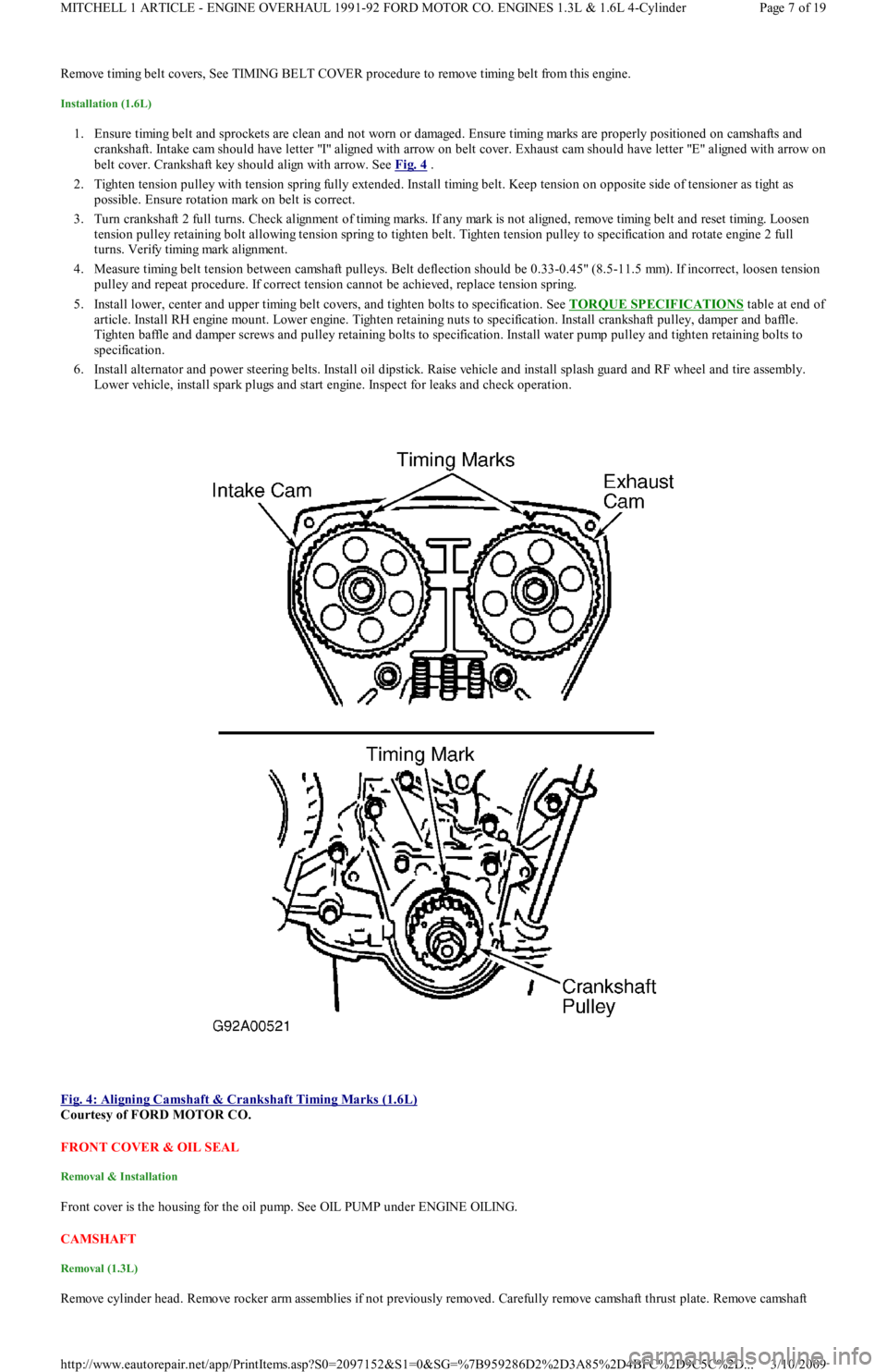
1. Ensure timing belt and sprockets are clean and not worn or damaged. Ensure timing marks are properly positioned on camshafts and
crankshaft. Intake cam should have letter "I" aligned with arrow on belt cover. Exhaust cam should have letter "E" aligned with arrow on
belt cover. Crankshaft key should align with arrow. See Fig. 4
.
2. Tighten tension pulley with tension spring fully extended. Install timing belt. Keep tension on opposite side of tensioner as tight as
possible. Ensure rotation mark on belt is correct.
3. Turn crankshaft 2 full turns. Check alignment of timing marks. If any mark is not aligned, remove timing belt and reset timing. Lo o se n
tension pulley retaining bolt allowing tension spring to tighten belt. Tighten tension pulley to specification and rotate engine 2 full
turns. Verify timing mark alignment.
4. Measure timing belt tension between camshaft pulleys. Belt deflection should be 0.33-0.45" (8.5-11.5 mm). If incorrect, loosen tension
pulley and repeat procedure. If correct tension cannot be achieved, replace tension spring.
5. Install lower, center and upper timing belt covers, and tighten bolts to specification. See TORQUE SPECIFICATIONS
table at end of
article. Install RH engine mount. Lower engine. Tighten retaining nuts to specification. Install crankshaft pulley, damper and baffle.
Tighten baffle and damper screws and pulley retaining bolts to specification. Install water pump pulley and tighten retaining bolts to
specification.
6. Install alternator and power steering belts. Install oil dipstick. Raise vehicle and install splash guard and RF wheel and tire assembly.
Lower vehicle, install spark plugs and start engine. Inspect for leaks and check operation.
Fig. 4: Aligning Camshaft & Crankshaft Timing Marks (1.6L)
Courtesy of FORD MOTOR CO.
FRONT COVER & OIL SEAL
Removal & Installation
Front cover is the housing for the oil pump. See OIL PUMP under ENGINE OILING.
CAMSHAFT
Removal (1.3L)
Remove cylinder head. Remove rocker arm assemblies if not previously removed. Carefully remove camshaft thrust plate. Remove camsh aft
Page 7 of 19 MITCHELL 1 ARTICLE - ENGINE OVERHAUL 1991-92 FORD MOTOR CO. ENGINES 1.3L & 1.6L 4-Cylinder
3/10/2009 http://www.eautorepair.net/app/PrintItems.asp?S0=2097152&S1=0&SG=%7B959286D2%2D3A85%2D4BFC%2D9C5C%2D
...
Page 153 of 454
Back To Article
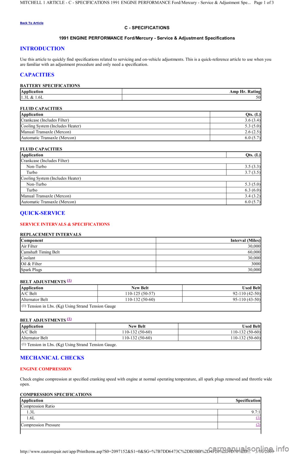
C - SPECIFICATIONS
1991 ENGINE PERFORMANCE Ford/Mercury - Service & Adjustm ent Specifications
INTRODUCTION
Use this article to quickly find specifications related to servicing and on-vehicle adjustments. This is a quick-reference article to use when you
are familiar with an adjustment procedure and only need a specification.
CAPACITIES
BATTERY SPECIFICATIONS
FLUID CAPACITIES
FLUID CAPACITIES
QUICK-SERVICE
SERVICE INTERVALS & SPECIFICATIONS
REPLACEMENT INTERVALS
BELT ADJUSTMENTS
(1)
BELT ADJUSTMENTS
(1)
MECHANICAL CHECKS
ENGINE COMPRESSION
Check engine compression at specified cranking speed with engine at normal operating temperature, all spark plugs removed and throttle wide
open.
COMPRESSION SPECIFICATIONS
ApplicationAmp Hr. Rating
1.3L & 1.6L50
ApplicationQts. (L)
Crankcase (Includes Filter)3.6 (3.4)
Cooling System (Includes Heater)5.3 (5.0)
Manual Transaxle (Mercon)2.6 (2.5)
Automatic Transaxle (Mercon)6.0 (5.7)
ApplicationQts. (L)
Crankcase (Includes Filter)
Non-Turbo3.5 (3.3)
Turbo3.7 (3.5)
Cooling System (Includes Heater)
Non-Turbo5.3 (5.0)
Turbo6.3 (6.0)
Manual Transaxle (Mercon)3.4 (3.2)
Automatic Transaxle (Mercon)6.0 (5.7)
ComponentInterval (Miles)
Air Filter30,000
Camsh aft Timin g Bel t60,000
Coolant30,000
Oil & Filter3000
Spark Plugs30,000
ApplicationNew BeltUsed Belt
A/C Belt110-125 (50-57)92-110 (42-50)
Alternator Belt110-132 (50-60)95-110 (43-50)
(1)Tension in Lbs. (Kg) Using Strand Tension Gauge
ApplicationNew BeltUsed Belt
A/C Belt110-132 (50-60)110-132 (50-60)
Alternator Belt110-132 (50-60)110-132 (50-60)
(1)Tension in Lbs. (Kg) Using Strand Tension Gauge.
ApplicationSpecification
Compression Ratio
1.3L9.7:1
1.6L(1)
Compression Pressure(2)
Page 1 of 3 MITCHELL 1 ARTICLE - C - SPECIFICATIONS 1991 ENGINE PERFORMANCE Ford/Mercury - Service & Adjustment Spe
...
3/10/2009 http://www.eautorepair.net/app/PrintItems.asp?S0=2097152&S1=0&SG=%7B7DD6473C%2DB5BB%2D4F20%2D9D70%2D
...
Page 214 of 454
Back To Article
GENERAL INFORMATION
T rouble Shooting - Basic Procedures
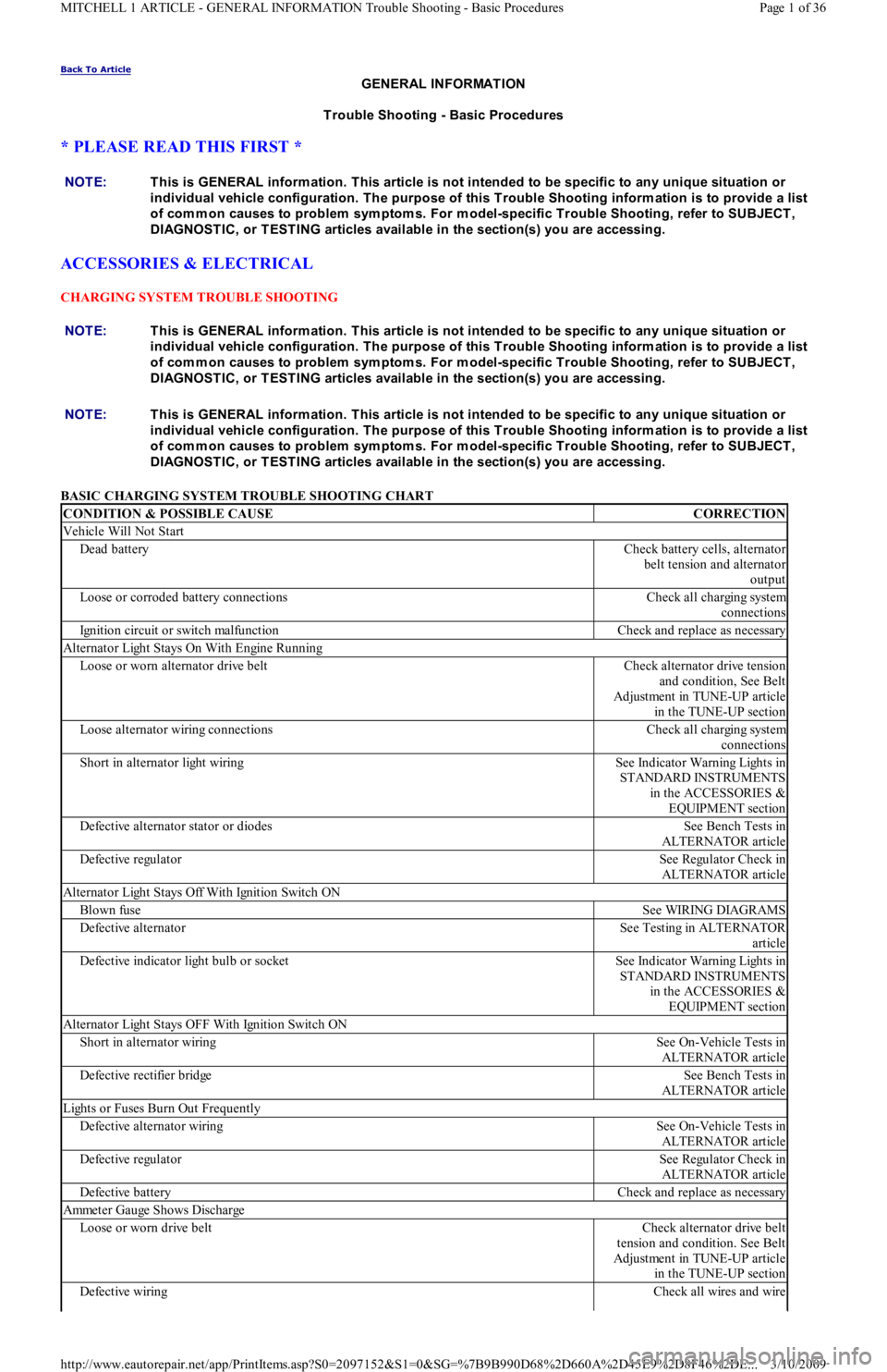
* PLEASE READ THIS FIRST *
ACCESSORIES & ELECTRICAL
CHARGING SYSTEM TROUBLE SHOOTING
BASIC CHARGING SYSTEM TROUBLE SHOOTING CHART NOTE:This is GENERAL inform ation. This article is not intended to be specific to any unique situation or
individual vehicle configuration. T he purpose of this T rouble Shooting inform ation is to provide a list
of com m on causes to problem sym ptom s. For m odel-specific T rouble Shooting, refer to SUBJECT ,
DIAGNOST IC, or T EST ING articles available in the section(s) you are accessing.
NOTE:This is GENERAL inform ation. This article is not intended to be specific to any unique situation or
individual vehicle configuration. T he purpose of this T rouble Shooting inform ation is to provide a list
of com m on causes to problem sym ptom s. For m odel-specific T rouble Shooting, refer to SUBJECT ,
DIAGNOST IC, or T EST ING articles available in the section(s) you are accessing.
CONDITION & POSSIBLE CAUSECORRECTION
Vehicle Will Not Start
Dead batteryCheck battery cells, alternator
belt tension and alternator
output
Loose or corroded battery connectionsCheck all charging system
connections
Ignition circuit or switch malfunctionCheck and replace as necessary
Alternator Light Stays On With Engine Running
Loose or worn alternator drive beltCheck alternator drive tension
and condition, See Belt
Adjustment in TUNE-UP article
in the TUNE-UP section
Loose alternator wiring connectionsCheck all charging system
connections
Short in alternator light wiringSee Indicator Warning Lights in
STANDARD INSTRUMENTS
in the ACCESSORIES &
EQUIPMENT section
Defective alternator stator or diodesSee Bench Tests in
ALTERNATOR article
Defective regulatorSee Regulator Check in
ALTERNATOR article
Alternator Light Stays Off With Ignition Switch ON
Blown fuseSee WIRING DIAGRAMS
Defective alternatorSee Testing in ALTERNATOR
article
Defective indicator light bulb or socketSee Indicator Warning Lights in
STANDARD INSTRUMENTS
in the ACCESSORIES &
EQUIPMENT section
Alternator Light Stays OFF With Ignition Switch ON
Short in alternator wiringSee On-Vehicle Tests in
ALTERNATOR article
Defective rectifier bridgeSee Bench Tests in
ALTERNATOR article
Lights or Fuses Burn Out Frequently
Defective alternator wiringSee On-Vehicle Tests in
ALTERNATOR article
Defective regulatorSee Regulator Check in
ALTERNATOR article
Defective batteryCheck and replace as necessary
Ammeter Gauge Shows Discharge
Loose or worn drive beltCheck alternator drive belt
tension and condition. See Belt
Adjustment in TUNE-UP article
in the TUNE-UP section
Defective wiringCheck all wires and wire
Page 1 of 36 MITCHELL 1 ARTICLE - GENERAL INFORMATION Trouble Shooting - Basic Procedures
3/10/2009 http://www.eautorepair.net/app/PrintItems.asp?S0=2097152&S1=0&SG=%7B9B990D68%2D660A%2D45E9%2D8F46%2DE
...
Page 215 of 454
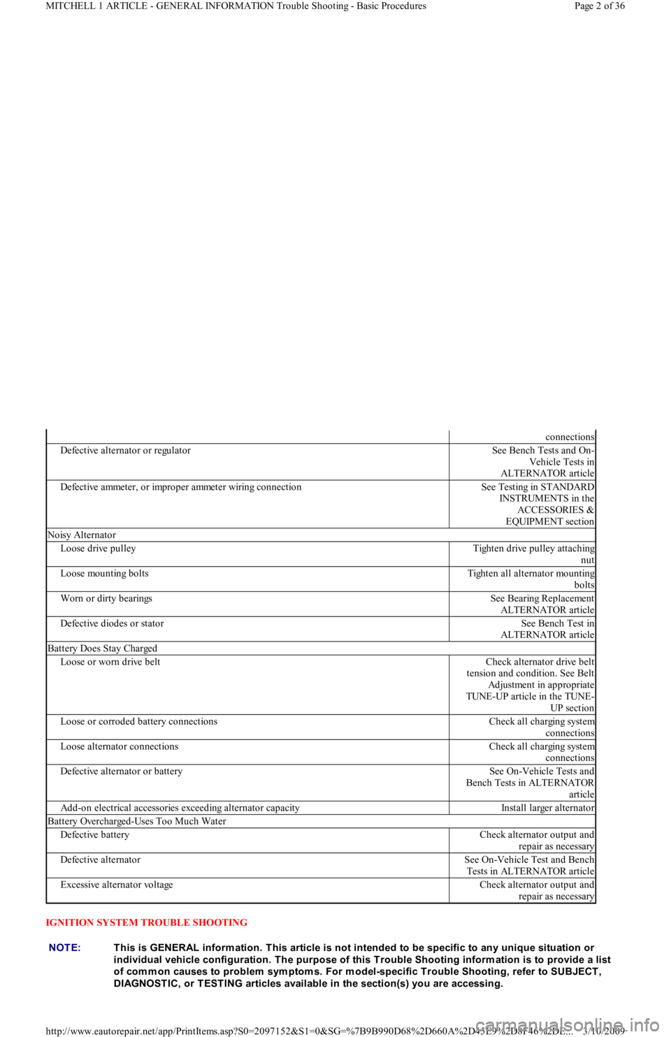
IGNITION SYSTEM TROUBLE SHOOTING
connections
Defective alternator or regulatorSee Bench Tests and On-
Vehicle Tests in
ALTERNATOR article
Defective ammeter, or improper ammeter wiring connectionSee Testing in STANDARD
INSTRUMENTS in the
ACCESSORIES &
EQUIPMENT section
Noisy Alternator
Loose drive pulleyTighten drive pulley attaching
nut
Loose mounting boltsTighten all alternator mounting
bolts
Worn or dirty bearingsSee Bearing Replacement
ALTERNATOR article
Defective diodes or statorSee Bench Test in
ALTERNATOR article
Battery Does Stay Charged
Loose or worn drive beltCheck alternator drive belt
tension and condition. See Belt
Adjustment in appropriate
TUNE-UP article in the TUNE-
UP section
Loose or corroded battery connectionsCheck all charging system
connections
Loose alternator connectionsCheck all charging system
connections
Defective alternator or batterySee On-Vehicle Tests and
Bench Tests in ALTERNATOR
article
Add-on electrical accessories exceeding alternator capacityInstall larger alternator
Battery Overcharged-Uses Too Much Water
Defective batteryCheck alternator output and
repair as necessary
Defective alternatorSee On-Vehicle Test and Bench
Tests in ALTERNATOR article
Excessive alternator voltageCheck alternator output and
repair as necessary
NOTE:This is GENERAL inform ation. This article is not intended to be specific to any unique situation or
individual vehicle configuration. T he purpose of this T rouble Shooting inform ation is to provide a list
of com m on causes to problem sym ptom s. For m odel-specific T rouble Shooting, refer to SUBJECT ,
DIAGNOST IC, or T EST ING articles available in the section(s) you are accessing.
Page 2 of 36 MITCHELL 1 ARTICLE - GENERAL INFORMATION Trouble Shooting - Basic Procedures
3/10/2009 http://www.eautorepair.net/app/PrintItems.asp?S0=2097152&S1=0&SG=%7B9B990D68%2D660A%2D45E9%2D8F46%2DE
...