1991 FORD FESTIVA fuse diagram
[x] Cancel search: fuse diagramPage 2 of 454
Back To Article
INST RUMENT PANEL
1991 ACCESSORIES & SAFET Y EQUIPMENT Ford Motor Co. Switches & Instrum ent Panels - Standard
DESCRIPTION & OPERATION
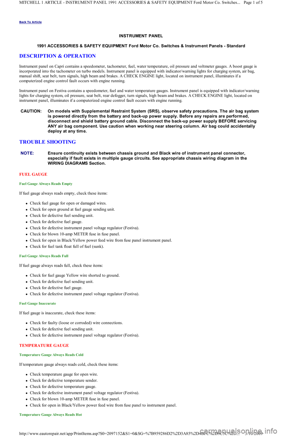
Instrument panel on Capri contains a speedometer, tachometer, fuel, water temperature, oil pressure and voltmeter gauges. A boost gauge is
incorporated into the tachometer on turbo models. Instrument panel is equipped with indicator/warning lights for charging system, air b ag,
manual shift, seat belt, turn signals, high beam and brakes. A CHECK ENGINE light, located on instrument panel, illuminates if a
computerized engine control fault occurs with engine running.
Instrument panel on Festiva contains a speedometer, fuel and water temperature gauges. Instrument panel is equipped with indicator/warning
lights for charging system, oil pressure, seat belt, rear defogger, turn signals, high beam and brakes. A CHECK ENGINE light, located on
instrument panel, illuminates if a computerized engine control fault occurs with engine running.
TROUBLE SHOOTING
FUEL GAUGE
Fuel Gauge Always Reads Empty
If fuel gauge always reads empty, check these items:
Check fuel gauge for open or damaged wires.
Check for open ground at fuel gauge sending unit.
Check for defective fuel sending unit.
Check for defective fuel gauge.
Check for defective instrument panel voltage regulator (Festiva).
Check for blown 10-amp METER fuse in fuse panel.
Check for open in Black/Yellow power feed wire from fuse panel instrument panel.
Check for fuel tank float full of fuel (sunk).
Fuel Gauge Always Reads Full
If fuel gauge always reads full, check these items:
Check for fuel gauge Yellow wire shorted to ground.
Check for defective fuel sending unit.
Check for defective fuel gauge.
Check for defective instrument panel voltage regulator (Festiva).
Fuel Gauge Inaccurate
If fuel gauge is inaccurate, check these items:
Check for faulty (loose or corroded) wire connections.
Check for defective fuel sending unit.
Check for defective instrument panel voltage regulator (Festiva).
TEMPERATURE GAUGE
Temperature Gauge Always Reads Cold
If temperature gauge always reads cold, check these items:
Check temperature gauge for open wire.
Check for defective temperature sender.
Check for defective temperature gauge.
Check for defective instrument panel voltage regulator (Festiva).
Check for blown 10-amp METER fuse in fuse panel.
Check for open in Black/Yellow power feed wire from fuse panel to instrument panel.
Temperature Gauge Always Reads Hot
CAUT ION: On m odels with Supplem ental Restraint System (SRS), observe safety precautions. T he air bag system
is powered directly from the battery and back-up power supply. Before any repairs are perform ed,
disconnect and shield battery ground cable. Disconnect the back-up power supply BEFORE servicing
ANY air bag com ponent. Use caution when working near steering colum n. Air bag could accidentally
deploy at any tim e.
NOTE:Ensure continuity exists between chassis ground and Black wire of instrum ent panel connector,
especially if fault exists in m ultiple gauge circuits. See appropriate chassis wiring diagram in the
WIRING DIAGRAMS Section.
Page 1 of 5 MITCHELL 1 ARTICLE - INSTRUMENT PANEL 1991 ACCESSORIES & SAFETY EQUIPMENT Ford Motor Co. Switches
...
3/10/2009 http://www.eautorepair.net/app/PrintItems.asp?S0=2097152&S1=0&SG=%7B959286D2%2D3A85%2D4BFC%2D9C5C%2D
...
Page 7 of 454
Back To Article
DEFOGGER - REAR WINDOW
1991 ACCESSORIES & SAFET Y EQUIPMENT Rear Window Defoggers - Rear Window
DESCRIPTION & OPERATION
The rear window defogger consists of an electrical grid on rear window glass. The rear window defogger switch is located in the instrument
cluster bezel. On Capri, the switch is a push type and includes a small indicator light in the switch to indicate when rear defogger is on. On
Festiva, the switch is a rocker type and includes a small indicator light in instrument cluster to indicate when rear defogger is on.
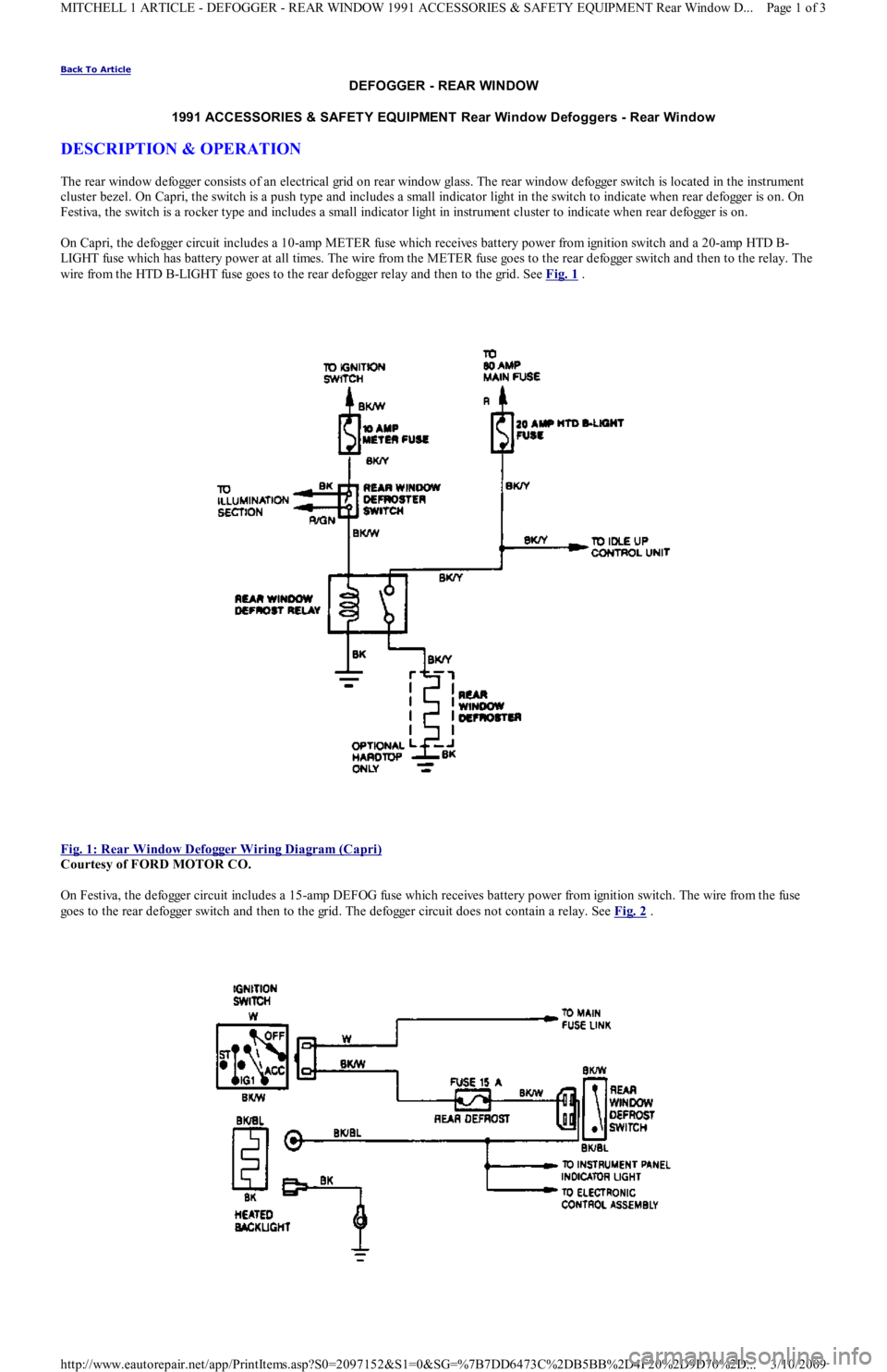
On Capri, the defogger circuit includes a 10-amp METER fuse which receives battery power from ignition switch and a 20-amp HTD B-
LIGHT fuse which has battery power at all times. The wire from the METER fuse goes to the rear defogger switch and then to the relay. The
wire from the HTD B-LIGHT fuse goes to the rear defogger relay and then to the grid. See Fig. 1
.
Fig. 1: Rear Window Defogger Wiring Diagram (Capri)
Courtesy of FORD MOTOR CO.
On Festiva, the defogger circuit includes a 15-amp DEFOG fuse which receives battery power from ignition switch. The wire from the fuse
goes to the rear defogger switch and then to the grid. The defogger circuit does not contain a relay. See Fig. 2
.
Page 1 of 3 MITCHELL 1 ARTICLE - DEFOGGER - REAR WINDOW 1991 ACCESSORIES & SAFETY EQUIPMENT Rear Window D
...
3/10/2009 http://www.eautorepair.net/app/PrintItems.asp?S0=2097152&S1=0&SG=%7B7DD6473C%2DB5BB%2D4F20%2D9D70%2D
...
Page 8 of 454
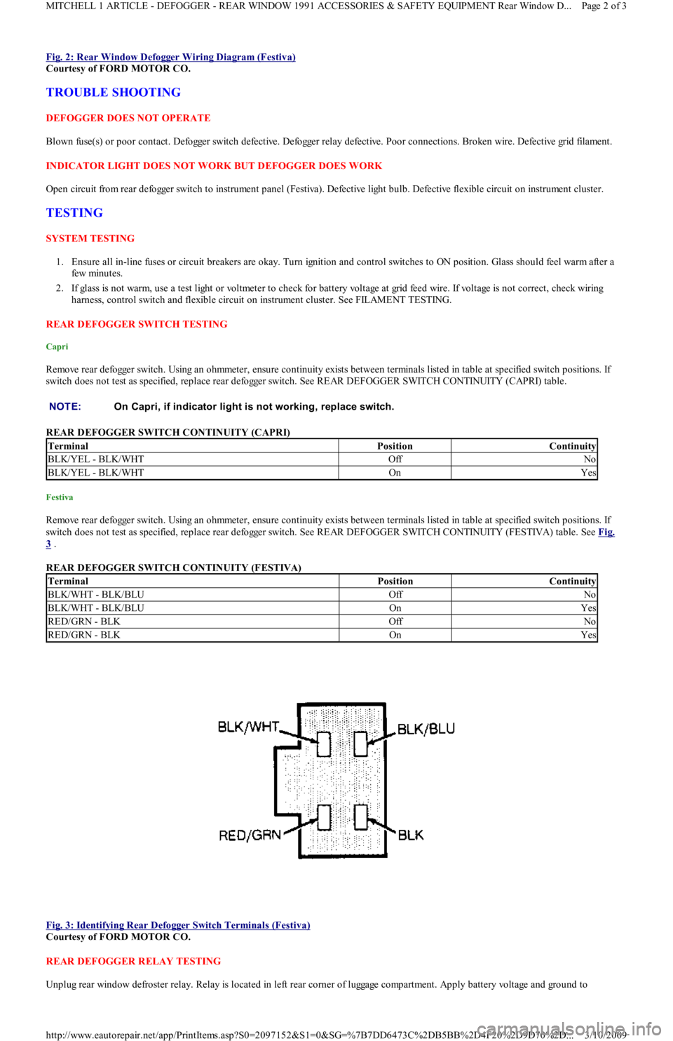
Fig. 2: Rear Window Defogger Wiring Diagram (Festiva)
Courtesy of FORD MOTOR CO.
TROUBLE SHOOTING
DEFOGGER DOES NOT OPERATE
Blown fuse(s) or poor contact. Defogger switch defective. Defogger relay defective. Poor connections. Broken wire. Defective grid filament.
INDICATOR LIGHT DOES NOT WORK BUT DEFOGGER DOES WORK
Open circuit from rear defogger switch to instrument panel (Festiva). Defective light bulb. Defective flexible circuit on instrument cluster.
TESTING
SYSTEM TESTING
1. Ensure all in-line fuses or circuit breakers are okay. Turn ignition and control switches to ON position. Glass should feel warm after a
few min u t es.
2. If glass is not warm, use a test light or voltmeter to check for battery voltage at grid feed wire. If voltage is not correct, check wiring
harness, control switch and flexible circuit on instrument cluster. See FILAMENT TESTING.
REAR DEFOGGER SWITCH TESTING
Capri
Remove rear defogger switch. Using an ohmmeter, ensure continuity exists between terminals listed in table at specified switch positions. If
switch does not test as specified, replace rear defogger switch. See REAR DEFOGGER SWITCH CONTINUITY (CAPRI) table.
REAR DEFOGGER SWITCH CONTINUITY (CAPRI)
Festiva
Remove rear defogger switch. Using an ohmmeter, ensure continuity exists between terminals listed in table at specified switch positions. If
switch does not test as specified, replace rear defogger switch. See REAR DEFOGGER SWITCH CONTINUITY (FESTIVA) table. See Fig.
3 .
REAR DEFOGGER SWITCH CONTINUITY (FESTIVA)
Fig. 3: Identifying Rear Defogger Switch Terminals (Festiva)
Courtesy of FORD MOTOR CO.
REAR DEFOGGER RELAY TESTING
Unplug rear window defroster relay. Relay is located in left rear corner of luggage compartment. Apply battery voltage and ground to NOTE:On Capri, if indicator light is not working, replace switch.
TerminalPositionContinuity
BLK/YEL - BLK/WHTOffNo
BLK/YEL - BLK/WHTOnYes
TerminalPositionContinuity
BLK/WHT - BLK/BLUOffNo
BLK/WHT - BLK/BLUOnYes
RED/GRN - BLKOffNo
RED/GRN - BLKOnYes
Page 2 of 3 MITCHELL 1 ARTICLE - DEFOGGER - REAR WINDOW 1991 ACCESSORIES & SAFETY EQUIPMENT Rear Window D
...
3/10/2009 http://www.eautorepair.net/app/PrintItems.asp?S0=2097152&S1=0&SG=%7B7DD6473C%2DB5BB%2D4F20%2D9D70%2D
...
Page 66 of 454

Autolamp Control RelayHeadlight Systems; Daytime Running Lights
Automatic Shutdown (ASD) RelayEngine Performance; Generators & Regulators
Autostick SwitchEngine Performance
Auxiliary Battery RelayGenerators & Regulators
Back-Up LightsBack-Up Lights; Exterior Lights
Barometric (BARO) Pressure SensorEngine Performance
BatteryPower Distribution
Battery Temperature SensorEngine Performance
Body Control ModuleBody Control Computer; Anti-Theft System; Daytime Running
Lights; Engine Performance; Headlight Systems; Warning Systems
Boost Control SolenoidEngine Performance
Boost SensorEngine Performance
Brake Fluid Level SwitchAnalog Instrument Panels
Brake On/Off (BOO) SwitchCruise Control Systems; Engine Performance; Shift Interlock
Systems
Buzzer ModuleWarning Systems
Camshaft Position (CMP) SensorEngine Performance
Central Control ModuleAnti-Theft System
ClockspringAir Bag Restraint System; Cruise Control Systems; Steering
Column Switches
Clutch Pedal Position SwitchStarters
Clutch Start SwitchStarters
Combination MeterAnalog Instrument Panels
Constant Control Relay Module (CCRM)Engine Performance; Electric Cooling Fans
Convenience CenterPower Distribution; Illumination/Interior Lights
Convertible Top MotorPower Convertible Top
Convertible Top SwitchPower Convertible Top
Crankshaft Position (CKP) SensorEngine Performance
Cruise Control ModuleCruise Control Systems
Cruise Control SwitchCruise Control Systems
Condenser Fan Relay(s)Electric Cooling Fans
Data Link Connector (DLC)Engine Performance
Da yt ime R u n n in g Ligh t s M o d u l eDaytime Running Lights; Exterior Lights
Defogger RelayRear Window Defogger
Diagnostic Energy Reserve Module (DERM)Air Bag Restraint System
Discriminating Sensor (Air Bag)Air Bag Restraint System
DistributorEngine Performance
Door Lock ActuatorsPower Door Locks; Remote Keyless Entry
Door Lock Relay(s)Power Door Locks
Electrochromic MirrorPower Mirrors
Electronic Level Control (ELC) Height SensorElectronic Suspension
Electronic Level Control (ELC) ModuleElectronic Suspension
Engine Coolant Temperature (ECT) Sending UnitAnalog Instrument Panels
Engine Coolant Temperature (ECT) SensorEngine Performance
Engine Control ModuleEngine Performance; Generators & Regulators; Starters
ETACS ECUWarning Systems; Power Windows; Remote Keyless Entry
Evaporative (EVAP) Emissions CanisterEngine Performance
EVAP Canister Purge SolenoidEngine Performance
EVAP Canister Vent SolenoidEngine Performance
Exhaust Gas Recirculation (EGR) ValveEngine Performance
Fuel Tank Vacuum SensorEngine Performance
F o g Ligh t sHeadlight Systems; Daytime Running Lights
F o g Ligh t R e l a yHeadlight Systems; Daytime Running Lights
Fuel Door Release SolenoidPower Fuel Door Release
Fuel Gauge Sending UnitAnalog Instrument Panels
Fuel InjectorsEngine Performance
Fuel PumpEngine Performance
Fuel Pump RelayEngine Performance; Power Distribution
Fuse/Relay BlockPower Distribution
Fusible LinksPower Distribution; Generators & Regulators; Starters
GeneratorGenerators & Regulators; Engine Performance; Power Distribution
Generic Electronic Module (GEM)Body Control Modules; Electronic Suspension
Glow Plug RelayEngine Performance
Glow PlugsEngine Performance
GroundsGround Distribution
Headlight Door ModuleHeadlight Doors
Headlight RelayHeadlight Systems; Daytime Running Lights
HeadlightsHeadlight Systems; Daytime Running Lights
Heated Oxygen Sensor(s) (HO2S)Engine Performance
Heated Windshield Control ModuleHeated Windshields
Page 4 of 6 MITCHELL 1 ARTICLE - GENERAL INFORMATION Using Mitchell1's Wiring Diagrams
3/10/2009 http://www.eautorepair.net/app/PrintItems.asp?S0=2097152&S1=0&SG=%7B959286D2%2D3A85%2D4BFC%2D9C5C%2D
...
Page 67 of 454

Height SensorElectronic Suspension
HornsSteering Column Switches
Horn RelaySteering Column Switches
Idle Air Control (IAC) Motor/ValveEngine Performance
Ignition Coil(s)Engine Performance
Ignition Key Lock CylinderAnti-Theft System
Ignition ModuleEngine Performance
Ignition SwitchPower Distribution; Engine Performance; Generators &
Regulators; Starters
Illuminated Entry ModuleIllumination/Interior Lights
Illumination LightsIllumination/Interior Lights
Impact SensorAir Bag Restraint System
Inertia Fuel Shutoff SwitchEngine Performance
In h ib it Rel ayStarters
Instrument ClusterAnalog Instrument Panels
Intake Air Temperature (IAT) SensorEngine Performance
Interior LightsIllumination/Interior Lights
In t erl o ck Swit chStarters
Junction BlockPower Distribution
Keyless Entry ReceiverRemote Keyless Entry
Key Reminder SwitchStarters
Knock SensorEngine Performance
Lamp Control ModuleExterior Lights
License Plate LampExterior Lights
Lighting Control ModuleLighting Control Modules; Anti-Theft System; Daytime Running
Lights; Headlight Systems
Lower RelayPower Convertible Top
Malfunction Indicator Light (MIL)Engine Performance; Instrument Panels
Manifold Absolute Pressure (MAP) SensorEngine Performance
Mass Airflow (MAF) SensorEngine Performance
Mega FuseGenerators & Regulators
Memory Seat/Mirror ModuleMemory Systems
M ir r o r De fo gge rRear Window Defogger
Moon Roof MotorPower Moon Roof
Moon Roof RelayPower Moon Roof
Multi-Function Control ModuleWarning Systems
Neutral Safety SwitchStarters
Oil Level SwitchEngine Performance
Oil Pressure Switch/Sending UnitAnalog Instrument Panels; Engine Performance
Overhead ConsoleOverhead Console
Oxygen Sensor(s) (O2S)Engine Performance
Parking Brake SwitchAnalog Instrument Panels
Park LightsExterior Lights
Park/Neutral Position SwitchStarters; Engine Performance; Anti-Theft System; Body Control
Module
Perimeter Lighting Control RelayExterior Lights
Power AmplifierPower Antennas
Power Antenna ModulePower Antennas
Power Antenna MotorPower Antennas
Power Distribution CenterPower Distribution; Generators & Regulators; Starters
Power Door Lock MotorsPower Door Locks
Power Mirror MotorsPower Mirrors; Memory Systems
Power Sliding Door ControllerPower Sliding Side Door
Power Seat MotorsPower Seats; Memory Systems
Power Steering Pressure SwitchEngine Performance
Power Top MotorPower Convertible Top
Power Top Relay(s)Power Convertible Top
Powertrain Control ModuleEngine Performance; Analog Instrument Panels; Cruise Control
Systems; Data Link Connectors; Generators & Regulators; Starters
Power Window MotorsPower Windows
Power Window Relay(s)Power Windows
Radiator Fan Motor(s)Electric Cooling Fans
Radiator Fan Relay(s)Engine Performance; Electric Cooling Fans;
Rainsense ModuleWiper/Washer Systems
Raise RelayPower Convertible Top
Remote Anti-Theft Personality (RAP) ModuleAnti-Theft System; Starters; Warning Systems
Seat Belt PretensionersAir Bag Restraint System
Seat Belt Retractor SolenoidPassive Restraints
Seat Belt SwitchAir Bag Restraint System; Passive Restraints
Shift Interlock SolenoidShift Interlock Systems
Page 5 of 6 MITCHELL 1 ARTICLE - GENERAL INFORMATION Using Mitchell1's Wiring Diagrams
3/10/2009 http://www.eautorepair.net/app/PrintItems.asp?S0=2097152&S1=0&SG=%7B959286D2%2D3A85%2D4BFC%2D9C5C%2D
...
Page 69 of 454
Back To Article
WIRING DIAGRAMS
1991 WIRING DIAGRAMS Ford Motor Co.
IDENTIFICATION
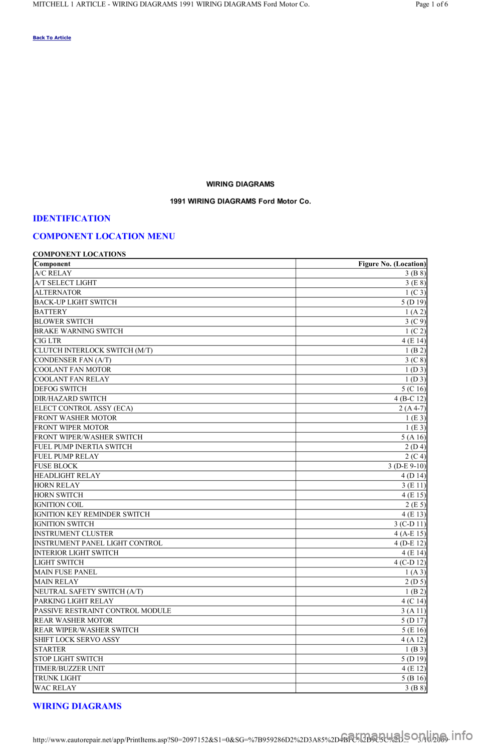
COMPONENT LOCATION MENU
COMPONENT LOCATIONS
WIRING DIAGRAMS
ComponentFigure No. (Location)
A/C RELAY3 (B 8)
A/T SELECT LIGHT3 (E 8)
ALTERNATOR1 (C 3)
BACK-UP LIGHT SWITCH5 (D 19)
BATTERY1 (A 2)
BLOWER SWITCH3 (C 9)
BRAKE WARNING SWITCH1 (C 2)
CIG LTR4 (E 14)
CLUTCH INTERLOCK SWITCH (M/T)1 (B 2)
CONDENSER FAN (A/T)3 (C 8)
COOLANT FAN MOTOR1 (D 3)
COOLANT FAN RELAY1 (D 3)
DEFOG SWITCH5 (C 16)
DIR/HAZARD SWITCH4 (B-C 12)
ELECT CONTROL ASSY (ECA)2 (A 4-7)
FRONT WASHER MOTOR1 (E 3)
FRONT WIPER MOTOR1 (E 3)
FRONT WIPER/WASHER SWITCH5 (A 16)
FUEL PUMP INERTIA SWITCH2 (D 4)
FUEL PUMP RELAY2 (C 4)
FUSE BLOCK3 (D-E 9-10)
HEADLIGHT RELAY4 (D 14)
HORN RELAY3 (E 11)
HORN SWITCH4 (E 15)
IGNITION COIL2 (E 5)
IGNITION KEY REMINDER SWITCH4 (E 13)
IGNITION SWITCH3 (C-D 11)
INSTRUMENT CLUSTER4 (A-E 15)
INSTRUMENT PANEL LIGHT CONTROL4 (D-E 12)
INTERIOR LIGHT SWITCH4 (E 14)
LIGHT SWITCH4 (C-D 12)
MAIN FUSE PANEL1 (A 3)
MAIN RELAY2 (D 5)
NEUTRAL SAFETY SWITCH (A/T)1 (B 2)
PARKING LIGHT RELAY4 (C 14)
PASSIVE RESTRAINT CONTROL MODULE3 (A 11)
REAR WASHER MOTOR5 (D 17)
REAR WIPER/WASHER SWITCH5 (E 16)
SHIFT LOCK SERVO ASSY4 (A 12)
STARTER1 (B 3)
STOP LIGHT SWITCH5 (D 19)
TIMER/BUZZER UNIT4 (E 12)
TRUNK LIGHT5 (B 16)
WAC RELAY3 (B 8)
Page 1 of 6 MITCHELL 1 ARTICLE - WIRING DIAGRAMS 1991 WIRING DIAGRAMS Ford Motor Co.
3/10/2009 http://www.eautorepair.net/app/PrintItems.asp?S0=2097152&S1=0&SG=%7B959286D2%2D3A85%2D4BFC%2D9C5C%2D
...
Page 72 of 454
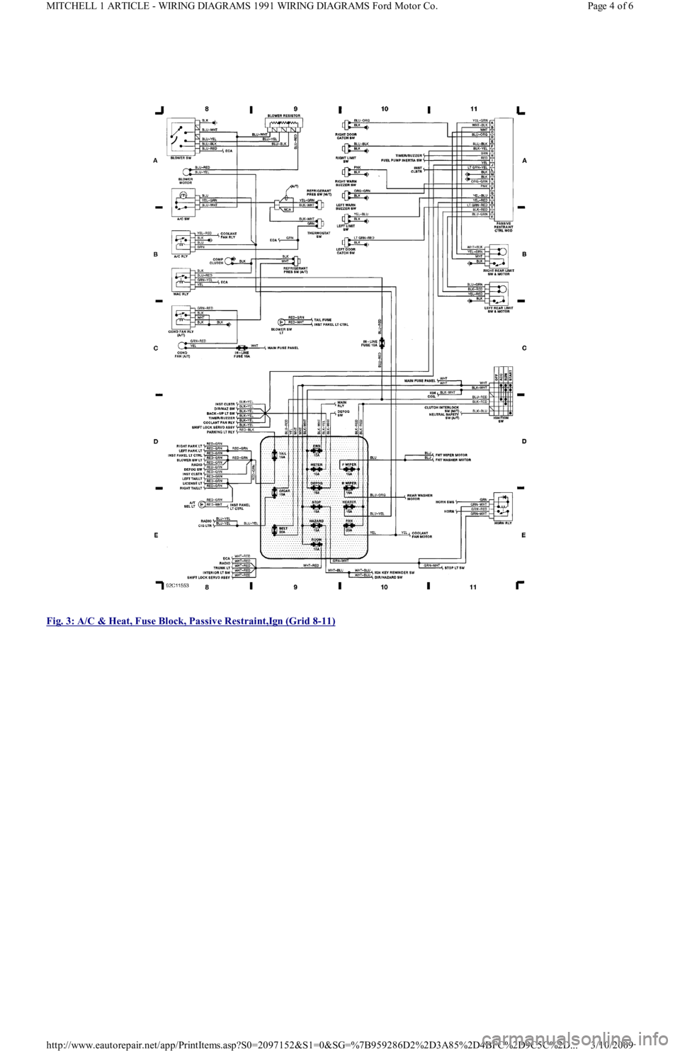
Fig. 3: A/C & Heat, Fuse Block, Passive Restraint,Ign (Grid 8
-11)
Page 4 of 6 MITCHELL 1 ARTICLE - WIRING DIAGRAMS 1991 WIRING DIAGRAMS Ford Motor Co.
3/10/2009 http://www.eautorepair.net/app/PrintItems.asp?S0=2097152&S1=0&SG=%7B959286D2%2D3A85%2D4BFC%2D9C5C%2D
...
Page 87 of 454
COOLING FAN DOES NOT RUN WITH A/C ON
If cooling fan does not run with A/C on, check the following items to help isolate fault.
Check A/C cooling fan relay.
Check cooling fan wiring harness.
TESTING
VOLTAGE SUPPLY TEST
Disconnect cooling fan motor connector. Turn ignition on. Check for voltage at Yellow wire terminal of connector. If voltage is NOT present,
check for blown 20-amp COOLING fuse (Capri) or C-FAN fuse (Festiva) or open in Yellow wire between cooling fan and fuse.
Disconnect cooling fan relay connector. Cooling fan relay is located in the left front corner of engine compartment. Turn ignition on. Check
for voltage at Yellow (Capri) or Black/Yellow (Festiva) wire terminal of connector. If voltage is NOT present, check for blown 30-amp
HEATER fuse on Capri or 10-amp METER fuse on Festiva or open in Black/Yellow wire between cooling fan relay and fuse.
Disconnect A/C cooling fan relay connector. On Capri, A/C relay is located in the left rear corner of the engine compartment, on firewall. On
Festiva, A/C relay is located in the left front corner of engine compartment, under a triple relay cover. Relay may be identified by wire colors
to relay connector. See Fig. 2
and Fig. 3 . Turn ignition on. Check for voltage at Blue wire terminal of connector. If voltage is NOT present,
check for blown 15-amp HEATER fuse or open in Blue wire between A/C cooling fan relay and fuse.
GROUND CIRCUIT TEST
Turn ignition off. Unplug connectors from cooling fan and A/C cooling fan relays. Check for continuity between ground and Black wire
terminal of relay connectors. If continuity is NOT present, repair Black ground wire.
FAN MOTOR TEST
Disconnect fan motor wire connector. Apply ground and battery voltage to motor connector. Fan should run. If fan does not run, replace
cooling fan motor.
COOLING FAN RELAY TEST
Unplug cooling fan relay connector. Apply battery voltage and ground to Yellow and Green/Red (Capri) or Black/Yellow and Green/Yellow
(Festiva) wire terminals of relay. Check continuity of relay across Yellow/Green (Capri) or Yellow/Red and Black (Festiva) wire connector
terminals. Ensure continuity is NOT present while relay is energized. When relay is de-energized, continuity should exist.
A/C COOLING FAN RELAY TEST
Unplug A/C relay connector. Apply battery voltage and ground to Blue and White (Capri) or Blue and Green (Festiva) wire terminals of relay.
Check continuity of relay across Blue and Red (Capri) or Yellow/Red and Black (Festiva) wire connector terminals. On Capri, ensure
continuity does NOT exist while relay is energized. On Festiva, ensure continuity exists while relay is energized. On Capri, when relay is de-
energized continuity should exist. On Festiva, when relay is de-energized, continuity should NOT exist.
COOLANT TEMPERATURE SWITCH TEST
Disconnect connector from coolant temperature switch located in thermostat housing. With coolant temperature less than 200°F (93°C) for
Capri or 194°F (90°C) for Festiva, check continuity between ground and coolant temperature switch. Ensure continuity exists. Start engine
and allow coolant temperature to reach 200°F (93°C) for Capri or 207°F (97°C) for Festiva. Check continuity between ground and coolant
temperature switch terminal. Continuity should NOT be present. If switch does not test as indicated, replace switch.
HARNESS & CIRCUIT CHECK TEST
Turn ignition off. Disconnect harness connectors of the following components: ECA, cooling fan motor, coolant temperature switch, cooling
fan relay and A/C cooling fan relay. Using an ohmmeter, check for continuity on the related harness leads of each connector. See Fig. 2
and
Fig. 3
.
WIRING DIAGRAMS
For further detail, see appropriate chassis wiring diagram in the WIRING DIAGRAMS article in the WIRING DIAGRAMS section.
Page 2 of 3 MITCHELL 1 ARTICLE - ENGINE COOLING FAN 1990-92 ENGINE COOLING Ford Motor Co. Engine Cooling Fans
3/10/2009 http://www.eautorepair.net/app/PrintItems.asp?S0=2097152&S1=0&SG=%7B959286D2%2D3A85%2D4BFC%2D9C5C%2D
...