1991 FORD FESTIVA seat adjustment
[x] Cancel search: seat adjustmentPage 32 of 454

lock nut. Discard axle lock nut. Separate tie rod end from knuckle.
2. Disconnect brake hose from strut (if necessary). Remove brake caliper assembly from knuckle and wire out of way. Remove nuts and
bolts holding ball joint and strut to knuckle assembly.
3. Remove knuckle assembly from ball joint and drive shaft. If binding occurs, use a dual-jawed puller to force knuckle/hub/rotor assembly
off drive axle shaft.
4. Using a puller, separate knuckle from wheel hub. Retain original outer bearing preload spacer to maintain bearing preload setting. If
replacing bearing, change spacer to maintain proper bearing preload (if necessary). See FRONT WHEEL BEARINGS under REMOVAL
& INSTALLATION. Scribe match marks between hub and rotor assembly. Remove rotor-to-hub bolts. Separate hub from rotor.
Installation
Align marks and install rotor on hub. Press knuckle and preload spacer into wheel hub assembly. To complete installation, reverse removal
procedure. Tighten axle shaft lock nut to 117-175 ft. lbs. (159-237 N.m).
REAR BRAKE CALIPER & PADS
Removal (Capri)
1. Raise and support vehicle. Remove tire and wheel assembly. Using needle-nose pliers, remove parking brake return spring. Loosen
parking brake cable housing adjusting nut. Remove cable housing from bracket on lower control arm. Loosen parking brake cable
bracket-to-caliper attaching bolt. Remove parking brake cable from caliper.
2. Remove lower caliper retaining bolt. Pivot caliper upward on upper caliper guide pin. Remove brake pad retaining spring, pads and
shims. If replacing rear brake pads only, reverse removal procedure to install. If removing caliper, proceed to next step.
3. Remove attaching clip from brake flex hose. Remove flex hose banjo bolt from caliper and discard copper washers. Remove lower
caliper retaining bolt. Using a cold chisel, remove upper caliper guide pin dust cap. Using an Allen wrench, remove upper caliper guide
pin. Lift caliper off rotor.
Installation
1. To install, fit brake pads and shims into caliper anchor plate. Remove upper guide pin and lower guide pin bushing from caliper.
Remove guide pin and guide pin bushing dust boots. Lubricate upper guide pin and lower guide pin bushing with Disc Brake Caliper
Slide Grease (D7AZ-19590-A).
2. To complete installation, reverse removal procedure. To fit caliper over new brake pads, it may be necessary to rotate caliper piston into
caliper bore. Use NEW copper washers on flex hose. Bleed brakes, and then pump brake pedal several times to seat pads.
REAR BRAKE ROTOR
Removal & Installation (Capri)
See REAR WHEEL BEARINGS under REMOVAL & INSTALLATION.
REAR BRAKE SHOES
Removal & Installation (Festiva)
Remove brake drum. Remove hold-down springs. Remove return springs. Remove self adjuster. See Fig. 8 . To install, reverse removal
procedure. Apply brake grease to all shoe contact points. See REAR BRAKE SHOES under ADJUSTMENTS.
REAR WHEEL CYLINDER
Removal & Installation (Festiva)
Remove rear brake shoes. Disconnect brake line from wheel cylinder. Remove wheel cylinder. To install, reverse removal procedure. Bleed
brake system.
MASTER BRAKE CYLINDER
Removal
Disconnect low fluid level sensor wiring (if equipped). Drain some brake fluid from reservoir. Disconnect brake lines from master cylinder.
Cap lines and master cylinder ports. Remove attaching nuts and master cylinder.
Installation
To install, reverse removal procedure. Fill master cylinder to proper level and bleed hydraulic system (if necessary).
POWER BRAKE UNIT
Removal & Installation
Remove master cylinder. Disconnect vacuum line. Remove clevis pin at brake pedal. Remove power brake unit. To install, reverse removal
procedure.
FRONT WHEEL BEARINGS NOTE:Hub and rotor are a m atched and balanced assem bly. Before rem oving rotor, locate paint or etch
m ark indicating proper hub-to-rotor alignm ent. If m arks are not present, m ark hub and rotor for
assem bly alignm ent. Failure to properly align hub and rotor can result in an im balance condition.
Page 5 of 12 MITCHELL 1 ARTICLE - BRAKE SYSTEM 1991-92 BRAKES Disc & Drum
3/10/2009 http://www.eautorepair.net/app/PrintItems.asp?S0=2097152&S1=0&SG=%7B7DD6473C%2DB5BB%2D4F20%2D9D70%2D
...
Page 101 of 454
Back To Article
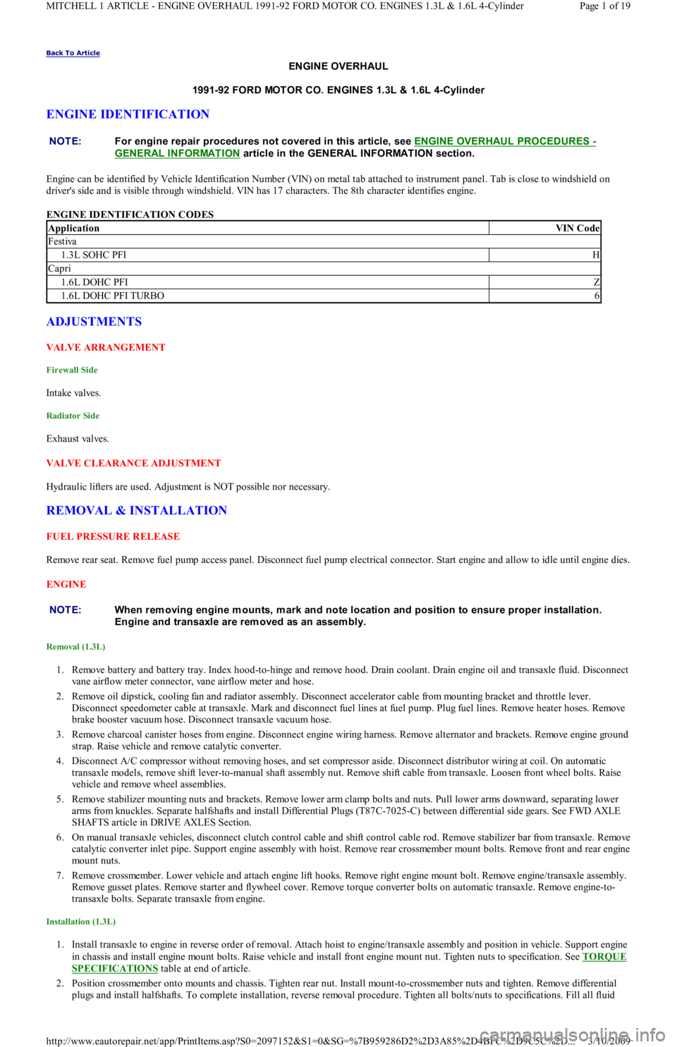
ENGINE OVERHAUL
1991-92 FORD MOT OR CO. ENGINES 1.3L & 1.6L 4-Cylinder
ENGINE IDENTIFICATION
Engine can be identified by Vehicle Identification Number (VIN) on metal tab attached to instrument panel. Tab is close to windshield on
driver's side and is visible through windshield. VIN has 17 characters. The 8th character identifies engine.
ENGINE IDENTIFICATION CODES
ADJUSTMENTS
VALVE ARRANGEMENT
Firewall Side
In t ake val ves.
Radiator Side
Exhaust valves.
VALVE CLEARANCE ADJUSTMENT
Hydraulic lifters are used. Adjustment is NOT possible nor necessary.
REMOVAL & INSTALLATION
FUEL PRESSURE RELEASE
Remove rear seat. Remove fuel pump access panel. Disconnect fuel pump electrical connector. Start engine and allow to idle until engine dies.
ENGINE
Removal (1.3L)
1. Remove battery and battery tray. Index hood-to-hinge and remove hood. Drain coolant. Drain engine oil and transaxle fluid. Disconnect
vane airflow meter connector, vane airflow meter and hose.
2. Remove oil dipstick, cooling fan and radiator assembly. Disconnect accelerator cable from mounting bracket and throttle lever.
Disconnect speedometer cable at transaxle. Mark and disconnect fuel lines at fuel pump. Plug fuel lines. Remove heater hoses. Remove
brake booster vacuum hose. Disconnect transaxle vacuum hose.
3. Remove charcoal canister hoses from engine. Disconnect engine wiring harness. Remove alternator and brackets. Remove engine ground
strap. Raise vehicle and remove catalytic converter.
4. Disconnect A/C compressor without removing hoses, and set compressor aside. Disconnect distributor wiring at coil. On automatic
transaxle models, remove shift lever-to-manual shaft assembly nut. Remove shift cable from transaxle. Loosen front wheel bolts. Raise
vehicle and remove wheel assemblies.
5. Remove stabilizer mounting nuts and brackets. Remove lower arm clamp bolts and nuts. Pull lower arms downward, separating lower
arms from knuckles. Separate halfshafts and install Differential Plugs (T87C-7025-C) between differential side gears. See FWD AXLE
SHAFTS article in DRIVE AXLES Section.
6. On manual transaxle vehicles, disconnect clutch control cable and shift control cable rod. Remove stabilizer bar from transaxle. Remove
catalytic converter inlet pipe. Support engine assembly with hoist. Remove rear crossmember mount bolts. Remove front and rear engine
mount nuts.
7. Remove crossmember. Lower vehicle and attach engine lift hooks. Remove right engine mount bolt. Remove engine/transaxle assembly.
Remove gusset plates. Remove starter and flywheel cover. Remove torque converter bolts on automatic transaxle. Remove engine-to-
transaxle bolts. Separate transaxle from engine.
Installation (1.3L)
1. Install transaxle to engine in reverse order of removal. Attach hoist to engine/transaxle assembly and position in vehicle. Support engine
in chassis and install engine mount bolts. Raise vehicle and install front engine mount nut. Tighten nuts to specification. See TORQUE
SPECIFICATIONS table at end of article.
2. Position crossmember onto mounts and chassis. Tighten rear nut. Install mount-to-crossmember nuts and tighten. Remove differential
plugs and install halfshafts. To complete installation, reverse removal procedure. Tighten all bolts/nuts to specifications. Fill all fluid NOTE:For engine repair procedures not covered in this article, see ENGINE OVERHAUL PROCEDURES
-
GENERAL INFORMATION
article in the GENERAL INFORMAT ION section.
ApplicationVIN Code
Festiva
1.3L SOHC PFIH
Capri
1.6L DOHC PFIZ
1.6L DOHC PFI TURBO6
NOTE:When rem oving engine m ounts, m ark and note location and position to ensure proper installation.
Engine and transaxle are rem oved as an assem bly.
Page 1 of 19 MITCHELL 1 ARTICLE - ENGINE OVERHAUL 1991-92 FORD MOTOR CO. ENGINES 1.3L & 1.6L 4-Cylinder
3/10/2009 http://www.eautorepair.net/app/PrintItems.asp?S0=2097152&S1=0&SG=%7B959286D2%2D3A85%2D4BFC%2D9C5C%2D
...
Page 102 of 454

levels to proper level.
Removal (1.6L & 1.6L Turbo)
1. Relieve fuel pressure and discharge air conditioning system (if equipped). See FUEL PRESSURE RELEASE under REMOVAL &
INSTALLATION. Disconnect and remove battery, battery tray and battery tray support bracket.
2. Release wiring harness retaining straps from battery support tray. Disconnect windshield washer supply hose between fluid reservoir and
hood. Mark hinge locations and remove hood.
3. Disconnect intake air tube and wiring to ignition coil and vane airflow meter. Remove air cleaner/vane airflow meter assembly. Remove
air cleaner assembly support brackets. Disconnect intercooler hoses from turbocharger (if equipped).
4. Drain engine coolant and remove radiator. Disconnect accelerator cable, and remove retaining bracket from cam cover. Position cable to
one side.
5. Disconnect and plug fuel lines at fuel filter and pressure regulator. Disconnect power brake booster manifold vacuum hose from
manifold. Disconnect heater hoses at heater core tubes. Label and remove vacuum hoses located at throttle body.
6. For manual transaxle turbocharged vehicles, disconnect clutch cable and remove support bracket and cable from transmission. On non-
turbo vehicles, disconnect clutch slave hydraulic line. For automatic transaxle, remove transaxle cooler lines.
7. Disconnect starter wiring at starter. Remove harness from locating strap on bracket. Disconnect alternator wiring. Disconnect wiring
from engine coolant sensors located on rear of engine block. Remove ground connection at bracket on thermostat cover. Disconnect O2
sensor wire, main wiring harness connector, TPS connector (turbocharged only), knock sensor connector, distributor wiring and
transaxle wiring. Disconnect ground wire and strap at front of engine, and reinstall lifting eye.
8. Remove engine oil dipstick and retaining clip. Remove power steering pump from mounting bracket. Remove power steering pump
mounting bracket. With hoses attached, position pump aside. Remove upper air conditioning compressor retaining bolts (if equipped).
9. Raise vehicle on hoist. Drain engine oil and cooling system. On vehicles with air conditioning, remove lower air conditioning
compressor mounting bolts, and position compressor out of way.
10. Remove front wheels and tires. Remove front ball joints-to-ste e r in g kn u c kl e s r e t a in in g b o l t s. R e mo ve sp l a sh gu a r d s. Dr a in t ransmission
oil and remove half shafts from differential. Remove front exhaust pipe bracket located on lower side of engine. Disconnect front
exhaust pipe from exhaust manifold, or turbocharger (if equipped).
11. Remove frame support bar-to-engine support bolt. Loosen right control arm bolt and, pivot support bar downward. Disengage rubber
exhaust hangers located directly behind catalytic converter. Allow exhaust system to hang down 6 inches, and support system with
mechanic's wire. Unbolt shift linkage and stabilizer bar at transaxle. Remove nuts from front and rear engine mounts, and lower vehicle.
12. Attach chains onto lift eyes at ends of cylinder head, and support engine with hoist. Remove RH engine mount through bolt. Raise
engine off mounts and slightly pivot engine/transaxle assembly. Disconnect oil pressure sensor and route starter/alternator wiring
harness from engine. Carefully lift engine/transaxle assembly, turn assembly while raising to clear brake master cylinder, shift linkage
universal joint, radiator support and air conditioning lines (if equipped).
13. Remove intake manifold support bracket. Remove gusset plate(s) (if equipped). Remove starter. Remove transaxle-to-engine retaining
bolts. Identify bolts to ensure correct installation. Separate transaxle from engine. On manual transaxle, remove pressure plate, clutch
disc and flywheel. On automatic transaxle, remove flexplate.
Installation (1.6L & 1.6L Turbo)
1. Install transaxle to engine in reverse order of removal. Attach hoist to engine/transaxle assembly and position assembly in vehicle.
Before engine contacts mounts, route starter, alternator and oil pressure sensor wiring, and connect oil pressure sensor. Lower engine
until front mount seats on crossmember. Install through bolt on RH engine mount. DO NOT tighten bolt.
2. Remove hoist. Raise vehicle and support with jackstands. Align rear engine mount to crossmember, and install retaining nuts to front
and rear engine mounts. Tighten nuts to specification. See TORQUE SPECIFICATIONS
table at end of article.
3. On manual transaxles, connect shift coupling and stabilizer. Tighten to specification. On automatic transaxles, connect shift linkage and
oil cooler lines. Tighten linkage retaining bolt, shift cable pivot and oil cooler hose clamps to specification. Connect front exhaust pipe
to manifold (or turbocharger). Install exhaust pipe to support bracket. Tighten bolts to specification. Tighten manifold (or turbocharger)
to specification. Attach rubber exhaust hangers. Position cross brace. Tighten retaining nut and bolt and right control arm front bolt.
4. Install drive axles. Install ball joint retaining bolts and tighten to specification. Mount A/C Compressor to engine (if equipped). Tighten
lower retaining bolts to specification. Install splash guards. Install tire and wheel assemblies. Tighten retaining nuts to specification.
5. Lower vehicle. Install upper A/C compressor retaining bolts (if equipped). Tighten bolts to specification. Tighten RH engine mo u n t
through bolt to specification. Connect alternator wiring.
6. Position power steering pump bracket on stud. Lower pump into engine compartment. Install power steering pump bracket retaining
bolts and nut. Tighten to specification. Install power steering pump and belt. Tighten adjustment nut and pivot bolt to specification.
7. Install engine oil dipstick and retaining clip. Install ground strap and ground wire to cylinder head. Install clutch cable (if equipped).
Connect clutch hydraulic line if equipped with manual transaxle or naturally aspirated. Connect transmission electrical connectors.
Connect fuel lines to fuel filter and pressure regulator. Install intake air tube to throttle body.
8. Install intercooler hoses on turbocharged models. Install air cleaner assembly brackets. Install air cleaner assembly with airflow meter
attached. Install intake air tube. Install coil and airflow meter connectors. Connect coolant crankcase and air bypass hoses. Install
vacuum hoses as noted in disassembly.
9. Connect accelerator cable. Install retaining bracket. Install power brake booster hose. Remove speedometer cable from transaxle. Fill
transaxle to specification. See CAPACITIES in SERVICE & ADJUSTMENT SPECIFICATIONS article. Install speedometer cable.
Connect speedometer cable connector. Fill engine oil to capacity.
10. Install radiator/fan assembly. Tighten bracket retaining bolts to specification. Connect coolant hoses and fan electrical connector. Fill
coolant to specification.
11. Install hood and connect washer hose. Install battery tray support, battery tray, battery and battery hold-down. Connect battery
terminal. Evacuate and charge air conditioning system (if equipped). Road test vehicle and inspect for leaks.
INTAKE MANIFOLD
Removal (1.3L)
CAUT ION: DO NOT allow com pressor to hang by hoses. T ie up com pressor with m echanic's wire.
Page 2 of 19 MITCHELL 1 ARTICLE - ENGINE OVERHAUL 1991-92 FORD MOTOR CO. ENGINES 1.3L & 1.6L 4-Cylinder
3/10/2009 http://www.eautorepair.net/app/PrintItems.asp?S0=2097152&S1=0&SG=%7B959286D2%2D3A85%2D4BFC%2D9C5C%2D
...
Page 112 of 454
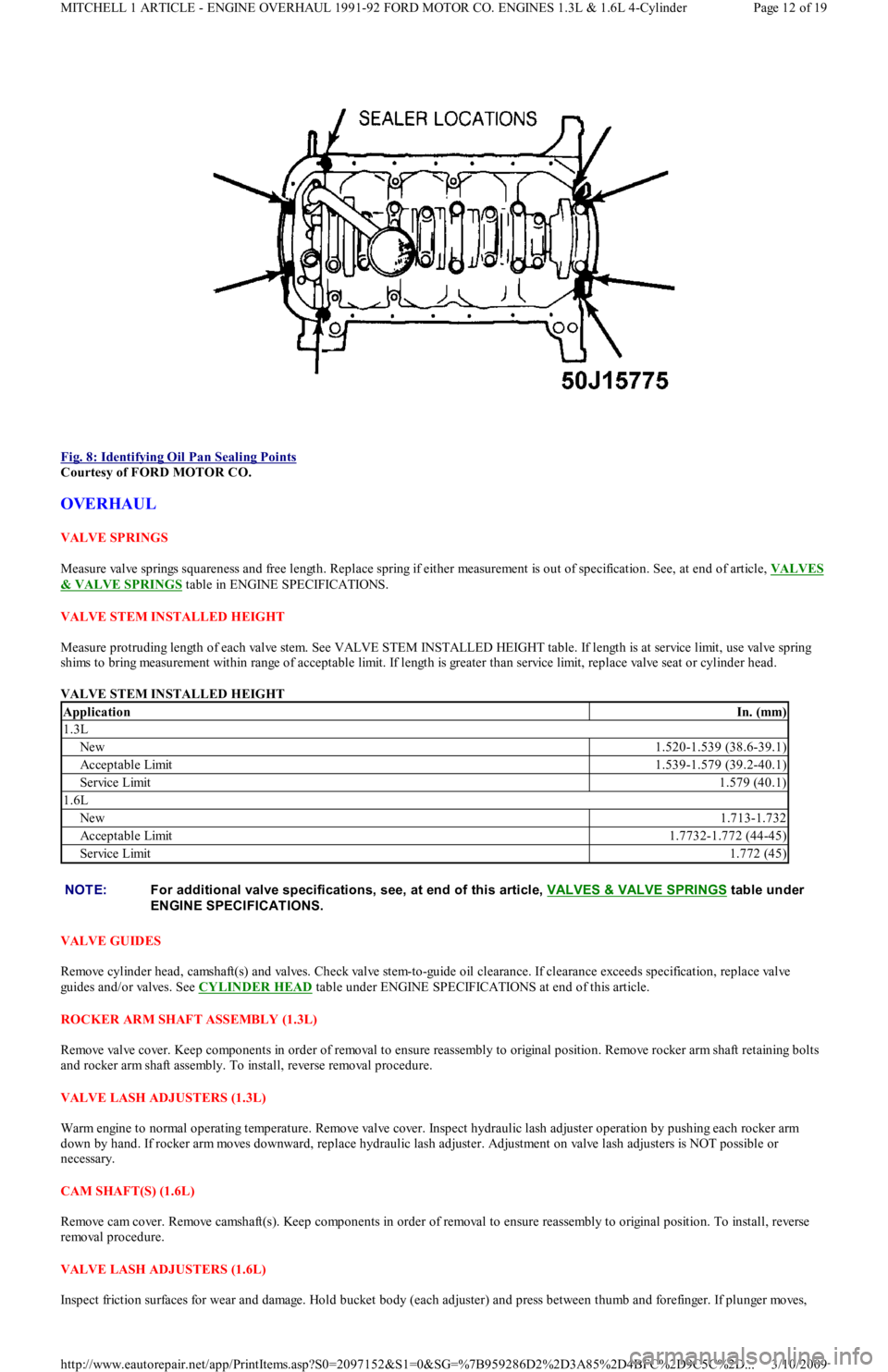
Fig. 8: Identifying Oil Pan Sealing Points
Courtesy of FORD MOTOR CO.
OVERHAUL
VALVE SPRINGS
Measure valve springs squareness and free length. Replace spring if either measurement is out of specification. See, at end of article, VALVES
& VALVE SPRINGS table in ENGINE SPECIFICATIONS.
VALVE STEM INSTALLED HEIGHT
Measure protruding length of each valve stem. See VALVE STEM INSTALLED HEIGHT table. If length is at service limit, use valve spring
shims to bring measurement within range of acceptable limit. If length is greater than service limit, replace valve seat or cylinder head.
VALVE STEM INSTALLED HEIGHT
VALVE GUIDES
Remove cylinder head, camshaft(s) and valves. Check valve stem-to-guide oil clearance. If clearance exceeds specification, replace valve
guides and/or valves. See CYLINDER HEAD
table under ENGINE SPECIFICATIONS at end of this article.
ROCKER ARM SHAFT ASSEMBLY (1.3L)
Remove valve cover. Keep components in order of removal to ensure reassembly to original position. Remove rocker arm shaft retaining bolts
and rocker arm shaft assembly. To install, reverse removal procedure.
VALVE LASH ADJUSTERS (1.3L)
Warm engine to normal operating temperature. Remove valve cover. Inspect hydraulic lash adjuster operation by pushing each rocker arm
down by hand. If rocker arm moves downward, replace hydraulic lash adjuster. Adjustment on valve lash adjusters is NOT possible or
necessary.
CAM SHAFT(S) (1.6L)
Remove cam cover. Remove camshaft(s). Keep components in order of removal to ensure reassembly to original position. To install, reverse
removal procedure.
VALVE LASH ADJUSTERS (1.6L)
Inspect friction surfaces for wear and damage. Hold bucket body (each adjuster) and press between thumb and forefinger. If plunge r mo ve s,
ApplicationIn. (mm)
1.3L
New1.520-1.539 (38.6-39.1)
Acceptable Limit1.539-1.579 (39.2-40.1)
Service Limit1.579 (40.1)
1.6L
New1.713-1.732
Acceptable Limit1.7732-1.772 (44-45)
Service Limit1.772 (45)
NOTE:For additional valve specifications, see, at end of this article, VALVES & VALVE SPRINGS
table under
ENGINE SPECIFICAT IONS.
Page 12 of 19 MITCHELL 1 ARTICLE - ENGINE OVERHAUL 1991-92 FORD MOTOR CO. ENGINES 1.3L & 1.6L 4-Cylinder
3/10/2009 http://www.eautorepair.net/app/PrintItems.asp?S0=2097152&S1=0&SG=%7B959286D2%2D3A85%2D4BFC%2D9C5C%2D
...
Page 236 of 454
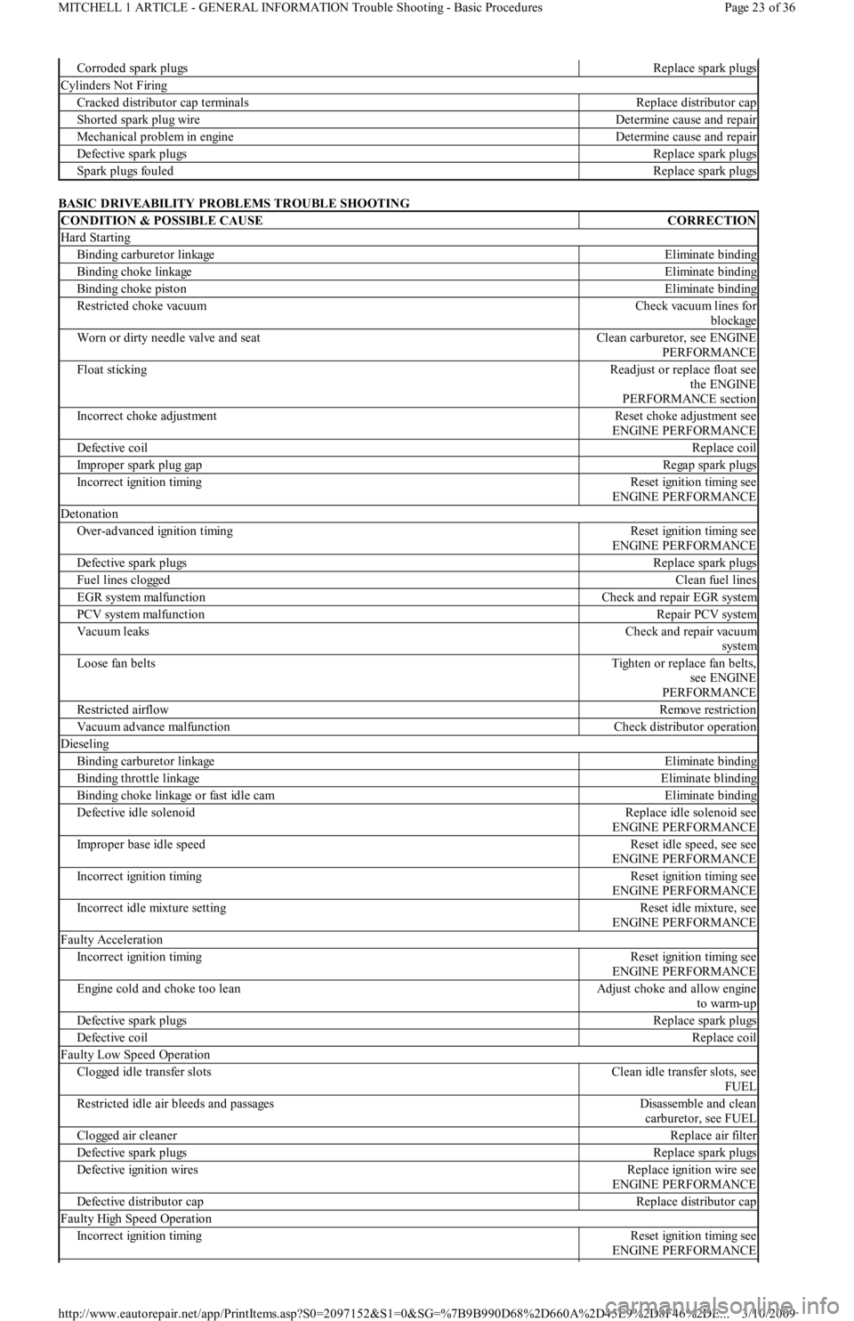
BASIC DRIVEABILITY PROBLEMS TROUBLE SHOOTING
Corroded spark plugsReplace spark plugs
Cylinders Not Firing
Cracked distributor cap terminalsReplace distributor cap
Shorted spark plug wireDetermine cause and repair
Mechanical problem in engineDetermine cause and repair
Defective spark plugsReplace spark plugs
Spark plugs fouledReplace spark plugs
CONDITION & POSSIBLE CAUSECORRECTION
Hard Starting
Binding carburetor linkageEliminate binding
Binding choke linkageEliminate binding
Binding choke pistonEliminate binding
Restricted choke vacuumCheck vacuum lines for
blockage
Worn or dirty needle valve and seatClean carburetor, see ENGINE
PERFORMANCE
Float stickingReadjust or replace float see
the ENGINE
PERFORMANCE section
Incorrect choke adjustmentReset choke adjustment see
ENGINE PERFORMANCE
Defective coilReplace coil
Improper spark plug gapRegap spark plugs
Incorrect ignition timingReset ignition timing see
ENGINE PERFORMANCE
Detonation
Over-advanced ignition timingReset ignition timing see
ENGINE PERFORMANCE
Defective spark plugsReplace spark plugs
Fuel lines cloggedClean fuel lines
EGR system malfunctionCheck and repair EGR system
PCV system malfunctionRepair PCV system
Vacuum leaksCheck and repair vacuum
system
Loose fan beltsTighten or replace fan belts,
see ENGINE
PERFORMANCE
Restricted airflowRemove restriction
Vacuum advance malfunctionCheck distributor operation
Dieseling
Binding carburetor linkageEliminate binding
Binding throttle linkageEliminate blinding
Binding choke linkage or fast idle camEliminate binding
Defective idle solenoidReplace idle solenoid see
ENGINE PERFORMANCE
Improper base idle speedReset idle speed, see see
ENGINE PERFORMANCE
Incorrect ignition timingReset ignition timing see
ENGINE PERFORMANCE
Incorrect idle mixture settingReset idle mixture, see
ENGINE PERFORMANCE
Faulty Acceleration
Incorrect ignition timingReset ignition timing see
ENGINE PERFORMANCE
Engine cold and choke too leanAdjust choke and allow engine
to warm-up
Defective spark plugsReplace spark plugs
Defective coilReplace coil
Faulty Low Speed Operation
Clogged idle transfer slotsClean idle transfer slots, see
FUEL
Restricted idle air bleeds and passagesDisassemble and clean
carburetor, see FUEL
Clogged air cleanerReplace air filter
Defective spark plugsReplace spark plugs
Defective ignition wiresReplace ignition wire see
ENGINE PERFORMANCE
Defective distributor capReplace distributor cap
Faulty High Speed Operation
Incorrect ignition timingReset ignition timing see
ENGINE PERFORMANCE
Page 23 of 36 MITCHELL 1 ARTICLE - GENERAL INFORMATION Trouble Shooting - Basic Procedures
3/10/2009 http://www.eautorepair.net/app/PrintItems.asp?S0=2097152&S1=0&SG=%7B9B990D68%2D660A%2D45E9%2D8F46%2DE
...
Page 238 of 454
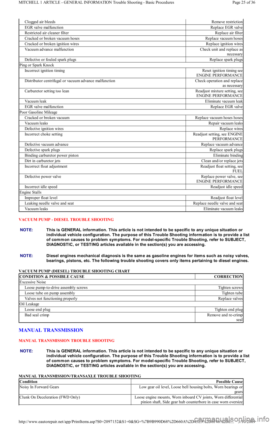
VACUUM PUMP - DIESEL TROUBLE SHOOTING
VACUUM PUMP (DIESEL) TROUBLE SHOOTING CHART
MANUAL TRANSMISSION
MANUAL TRANSMISSION TROUBLE SHOOTING
MANUAL TRANSMISSION/TRANSAXLE TROUBLE SHOOTING
Clogged air bleedsRemove restriction
EGR valve malfunctionReplace EGR valve
Restricted air cleaner filterReplace air filter
Cracked or broken vacuum hosesReplace vacuum hoses
Cracked or broken ignition wiresReplace ignition wires
Vacuum advance malfunctionCheck unit and replace as
necessary
Defective or fouled spark plugsReplace spark plugs
Ping or Spark Knock
Incorrect ignition timingReset ignition timing see
ENGINE PERFORMANCE
Distributor centrifugal or vacuum advance malfunctionCheck operation and replace
as necessary
Carburetor setting too leanReadjust mixture setting, see
ENGINE PERFORMANCE
Vacuum leakEliminate vacuum leak
EGR valve malfunctionReplace EGR valve
Poor Gasoline Mileage
Cracked or broken vacuumReplace vacuum hoses hoses
Vacuum leaksRepair vacuum leaks
Defective ignition wiresReplace wires
Incorrect choke settingReadjust setting, see ENGINE
PERFORMANCE
Defective vacuum advanceReplace vacuum advance
Defective spark plugsReplace spark plugs
Binding carburetor power pistonEliminate binding
Dirt in carburetor jetsClean and/or replace jets
Incorrect float adjustmentReadjust float setting, see
FUEL
Defective power valveReplace power valve, see
ENGINE PERFORMANCE
Incorrect idle speedReadjust idle speed
Engine Stalls
Improper float levelReadjust float level
Leaking needle valve and seatReplace needle valve and seat
Vacuum leaksEliminate vacuum leaks
NOTE:This is GENERAL inform ation. This article is not intended to be specific to any unique situation or
individual vehicle configuration. T he purpose of this T rouble Shooting inform ation is to provide a list
of com m on causes to problem sym ptom s. For m odel-specific T rouble Shooting, refer to SUBJECT ,
DIAGNOST IC, or T EST ING articles available in the section(s) you are accessing.
NOTE:Diesel engines m echanical diagnosis is the sam e as gasoline engines for item s such as noisy valves,
bearings, pistons, etc. T he following trouble shooting covers only item s pertaining to diesel engines.
CONDITION & POSSIBLE CAUSECORRECTION
Excessive Noise
Loose pump-to-drive assembly screwsTighten screws
Loose tube on pump assemblyTighten tube
Valves not functioning properlyReplace valves
Oil Leakage
Loose end plugTighten end plug
Bad seal crimpRemove and re-crimp
seal
NOTE:This is GENERAL inform ation. This article is not intended to be specific to any unique situation or
individual vehicle configuration. T he purpose of this T rouble Shooting inform ation is to provide a list
of com m on causes to problem sym ptom s. For m odel-specific T rouble Shooting, refer to SUBJECT ,
DIAGNOST IC, or T EST ING articles available in the section(s) you are accessing.
ConditionPossible Cause
Noisy In Forward GearsLow gear oil level, Loose bell housing bolts, Worn bearings or
gears
Clunk On Deceleration (FWD Only)Loose engine mounts, Worn inboard CV joints, Worn differential
pinion shaft, Side gear hub counterbore in case worn oversize
Page 25 of 36 MITCHELL 1 ARTICLE - GENERAL INFORMATION Trouble Shooting - Basic Procedures
3/10/2009 http://www.eautorepair.net/app/PrintItems.asp?S0=2097152&S1=0&SG=%7B9B990D68%2D660A%2D45E9%2D8F46%2DE
...
Page 246 of 454
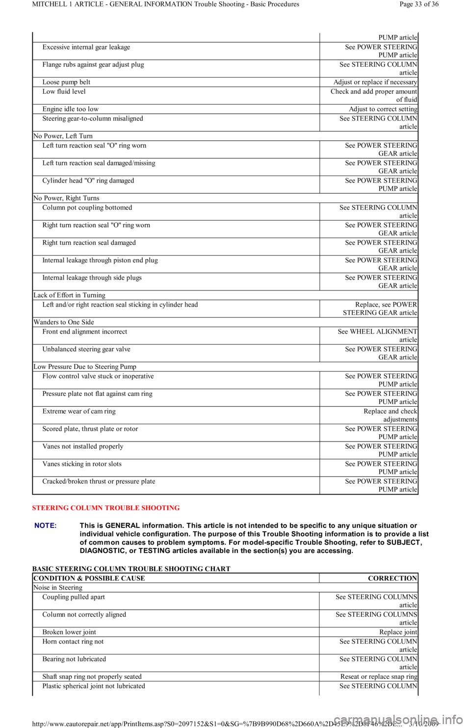
STEERING COLUMN TROUBLE SHOOTING
BASIC STEERING COLUMN TROUBLE SHOOTING CHART
PUMP article
Excessive internal gear leakageSee POWER STEERING
PUMP article
Flange rubs against gear adjust plugSee STEERING COLUMN
article
Loose pump beltAdjust or replace if necessary
Low fluid levelCheck and add proper amount
of fluid
Engine idle too lowAdjust to correct setting
Steering gear-to-column misalignedSee STEERING COLUMN
article
No Power, Left Turn
Left turn reaction seal "O" ring wornSee POWER STEERING
GEAR article
Left turn reaction seal damaged/missingSee POWER STEERING
GEAR article
Cylinder head "O" ring damagedSee POWER STEERING
PUMP article
No Power, Right Turns
Column pot coupling bottomedSee STEERING COLUMN
article
Right turn reaction seal "O" ring wornSee POWER STEERING
GEAR article
Right turn reaction seal damagedSee POWER STEERING
GEAR article
Internal leakage through piston end plugSee POWER STEERING
GEAR article
Internal leakage through side plugsSee POWER STEERING
GEAR article
Lack of Effort in Turning
Left and/or right reaction seal sticking in cylinder headReplace, see POWER
STEERING GEAR article
Wanders to One Side
Front end alignment incorrectSee WHEEL ALIGNMENT
article
Unbalanced steering gear valveSee POWER STEERING
GEAR article
Low Pressure Due to Steering Pump
Flow control valve stuck or inoperativeSee POWER STEERING
PUMP article
Pressure plate not flat against cam ringSee POWER STEERING
PUMP article
Extreme wear of cam ringReplace and check
adjustments
Scored plate, thrust plate or rotorSee POWER STEERING
PUMP article
Vanes not installed properlySee POWER STEERING
PUMP article
Vanes sticking in rotor slotsSee POWER STEERING
PUMP article
Cracked/broken thrust or pressure plateSee POWER STEERING
PUMP article
NOTE:This is GENERAL inform ation. This article is not intended to be specific to any unique situation or
individual vehicle configuration. T he purpose of this T rouble Shooting inform ation is to provide a list
of com m on causes to problem sym ptom s. For m odel-specific T rouble Shooting, refer to SUBJECT ,
DIAGNOST IC, or T EST ING articles available in the section(s) you are accessing.
CONDITION & POSSIBLE CAUSECORRECTION
Noise in Steering
Coupling pulled apartSee STEERING COLUMNS
article
Column not correctly alignedSee STEERING COLUMNS
article
Broken lower jointReplace joint
Horn contact ring notSee STEERING COLUMN
article
Bearing not lubricatedSee STEERING COLUMN
article
Shaft snap ring not properly seatedReseat or replace snap ring
Plastic spherical joint not lubricatedSee STEERING COLUMN
Page 33 of 36 MITCHELL 1 ARTICLE - GENERAL INFORMATION Trouble Shooting - Basic Procedures
3/10/2009 http://www.eautorepair.net/app/PrintItems.asp?S0=2097152&S1=0&SG=%7B9B990D68%2D660A%2D45E9%2D8F46%2DE
...
Page 247 of 454
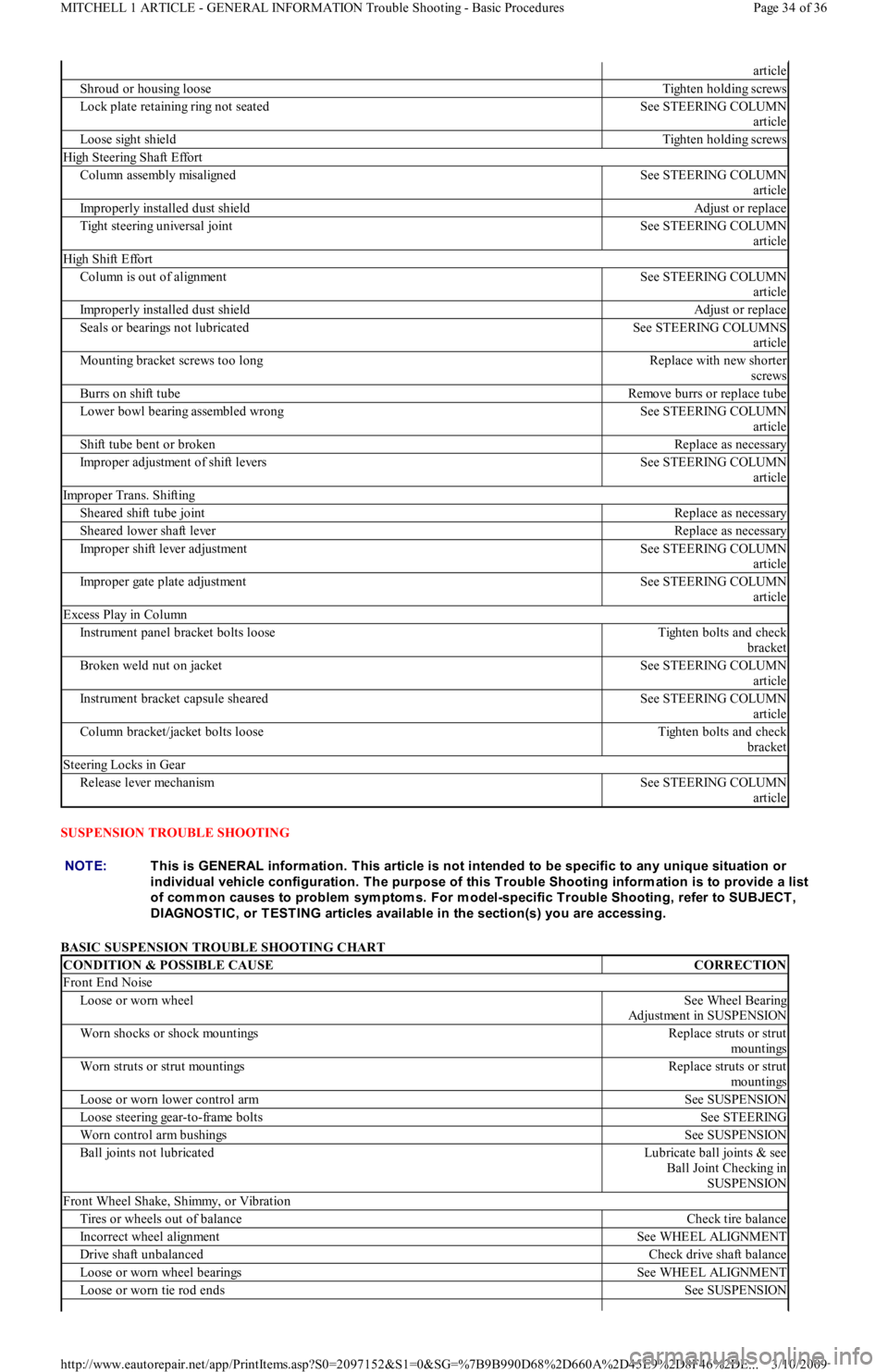
SUSPENSION TROUBLE SHOOTING
BASIC SUSPENSION TROUBLE SHOOTING CHART
article
Shroud or housing looseTighten holding screws
Lock plate retaining ring not seatedSee STEERING COLUMN
article
Loose sight shieldTighten holding screws
High Steering Shaft Effort
Co l u mn assemb l y misal ign edSee STEERING COLUMN
article
Improperly installed dust shieldAdjust or replace
Tight steering universal jointSee STEERING COLUMN
article
High Shift Effort
Column is out of alignmentSee STEERING COLUMN
article
Improperly installed dust shieldAdjust or replace
Seals or bearings not lubricatedSee STEERING COLUMNS
article
Mounting bracket screws too longReplace with new shorter
screws
Burrs on shift tubeRemove burrs or replace tube
Lower bowl bearing assembled wrongSee STEERING COLUMN
article
Shift tube bent or brokenReplace as necessary
Improper adjustment of shift leversSee STEERING COLUMN
article
Improper Trans. Shifting
Sheared shift tube jointReplace as necessary
Sheared lower shaft leverReplace as necessary
Improper shift lever adjustmentSee STEERING COLUMN
article
Improper gate plate adjustmentSee STEERING COLUMN
article
Excess Play in Column
Instrument panel bracket bolts looseTighten bolts and check
bracket
Broken weld nut on jacketSee STEERING COLUMN
article
Instrument bracket capsule shearedSee STEERING COLUMN
article
Column bracket/jacket bolts looseTighten bolts and check
bracket
Steering Locks in Gear
Release lever mechanismSee STEERING COLUMN
article
NOTE:This is GENERAL inform ation. This article is not intended to be specific to any unique situation or
individual vehicle configuration. T he purpose of this T rouble Shooting inform ation is to provide a list
of com m on causes to problem sym ptom s. For m odel-specific T rouble Shooting, refer to SUBJECT ,
DIAGNOST IC, or T EST ING articles available in the section(s) you are accessing.
CONDITION & POSSIBLE CAUSECORRECTION
Front End Noise
Loose or worn wheelSee Wheel Bearing
Adjustment in SUSPENSION
Worn shocks or shock mountingsReplace struts or strut
mo u n t in gs
Worn struts or strut mountingsReplace struts or strut
mo u n t in gs
Loose or worn lower control armSee SUSPENSION
Loose steering gear-to-frame boltsSee STEERING
Worn control arm bushingsSee SUSPENSION
Ball joints not lubricatedLubricate ball joints & see
Ball Joint Checking in
SUSPENSION
Front Wheel Shake, Shimmy, or Vibration
Tires or wheels out of balanceCheck tire balance
Incorrect wheel alignmentSee WHEEL ALIGNMENT
Drive shaft unbalancedCheck drive shaft balance
Loose or worn wheel bearingsSee WHEEL ALIGNMENT
Loose or worn tie rod endsSee SUSPENSION
Page 34 of 36 MITCHELL 1 ARTICLE - GENERAL INFORMATION Trouble Shooting - Basic Procedures
3/10/2009 http://www.eautorepair.net/app/PrintItems.asp?S0=2097152&S1=0&SG=%7B9B990D68%2D660A%2D45E9%2D8F46%2DE
...