1991 FORD FESTIVA interior lights
[x] Cancel search: interior lightsPage 49 of 454
Back To Article
FUSES & CIRCUIT BREAKERS
Fuses & Circuit Breakers 1988-93 Festiva
FUSES & FUSIBLE LINKS
FUSE PANEL & FUSIBLE LINK BLOCK LOCATIONS
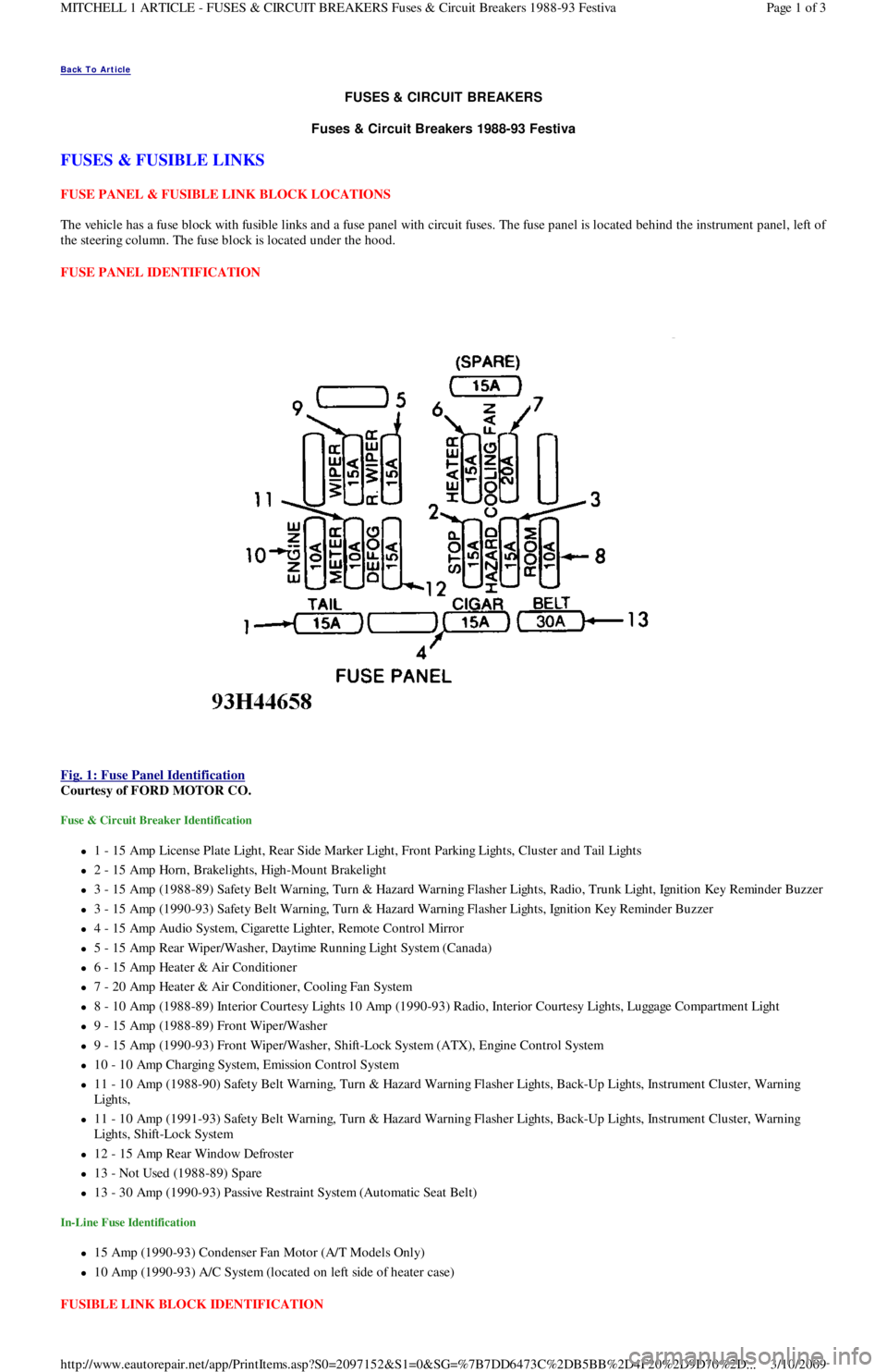
The vehicle has a fuse block with fusible links and a fuse panel with circuit fuses. The fuse panel is located behind the instrument panel, left o
f
the steering column. The fuse block is located under the hood.
FUSE PANEL IDENTIFICATION
Fig. 1: Fuse Panel Identification
Courtesy of FORD MOTOR CO.
Fuse & Circuit Breaker Identification
1 - 15 Amp License Plate Light, Rear Side Marker Ligh t , Fr o n t P a r kin g Ligh t s, C l u st e r a n d Ta il Ligh t s
2 - 15 Amp Horn, Brakelights, High-Mount Brakelight
3 - 15 Amp (1988-89) Safety Belt Warning, Turn & Hazard Warning Flasher Lights, Radio, Trunk Light, Ignition Key Reminder Buzzer
3 - 15 Amp (1990-93) Safety Belt Warning, Turn & Hazard Warning Flasher Lights, Ignition Key Reminder Buzzer
4 - 15 Amp Audio System, Cigarette Lighter, Remote Control Mirror
5 - 15 Amp Rear Wiper/Washer, Daytime Running Light System (Canada)
6 - 15 Amp Heater & Air Conditioner
7 - 20 Amp Heater & Air Conditioner, Cooling Fan System
8 - 10 Amp (1988-89) Interior Courtesy Lights 10 Amp (1990-93) Radio, Interior Courtesy Lights, Luggage Compartment Light
9 - 15 Amp (1988-89) Front Wiper/Washer
9 - 15 Amp (1990-93) Front Wiper/Washer, Shift-Lock System (ATX), Engine Control System
10 - 10 Amp Charging System, Emission Control System
11 - 10 Amp (1988-90) Safety Belt Warning, Turn & Hazard Warning Flasher Lights, Back-Up Lights, Instrument Cluster, Warning
Lights,
11 - 10 Amp (1991-93) Safety Belt Warning, Turn & Hazard Warning Flasher Lights, Back-Up Lights, Instrument Cluster, Warning
Lights, Shift-Lock System
12 - 15 Amp Rear Window Defroster
13 - Not Used (1988-89) Spare
13 - 30 Amp (1990-93) Passive Restraint System (Automatic Seat Belt)
In-Line Fuse Identification
15 Amp (1990-93) Condenser Fan Motor (A/T Models Only)
10 Amp (1990-93) A/C System (located on left side of heater case)
FUSIBLE LINK BLOCK IDENTIFICATION
Page 1 of 3 MITCHELL 1 ARTICLE - FUSES & CIRCUIT BREAKERS Fuses & Circuit Breakers 1988-93 Festiva
3/10/2009 http://www.eautorepair.net/app/PrintItems.asp?S0=2097152&S1=0&SG=%7B7DD6473C%2DB5BB%2D4F20%2D9D70%2D
...
Page 50 of 454
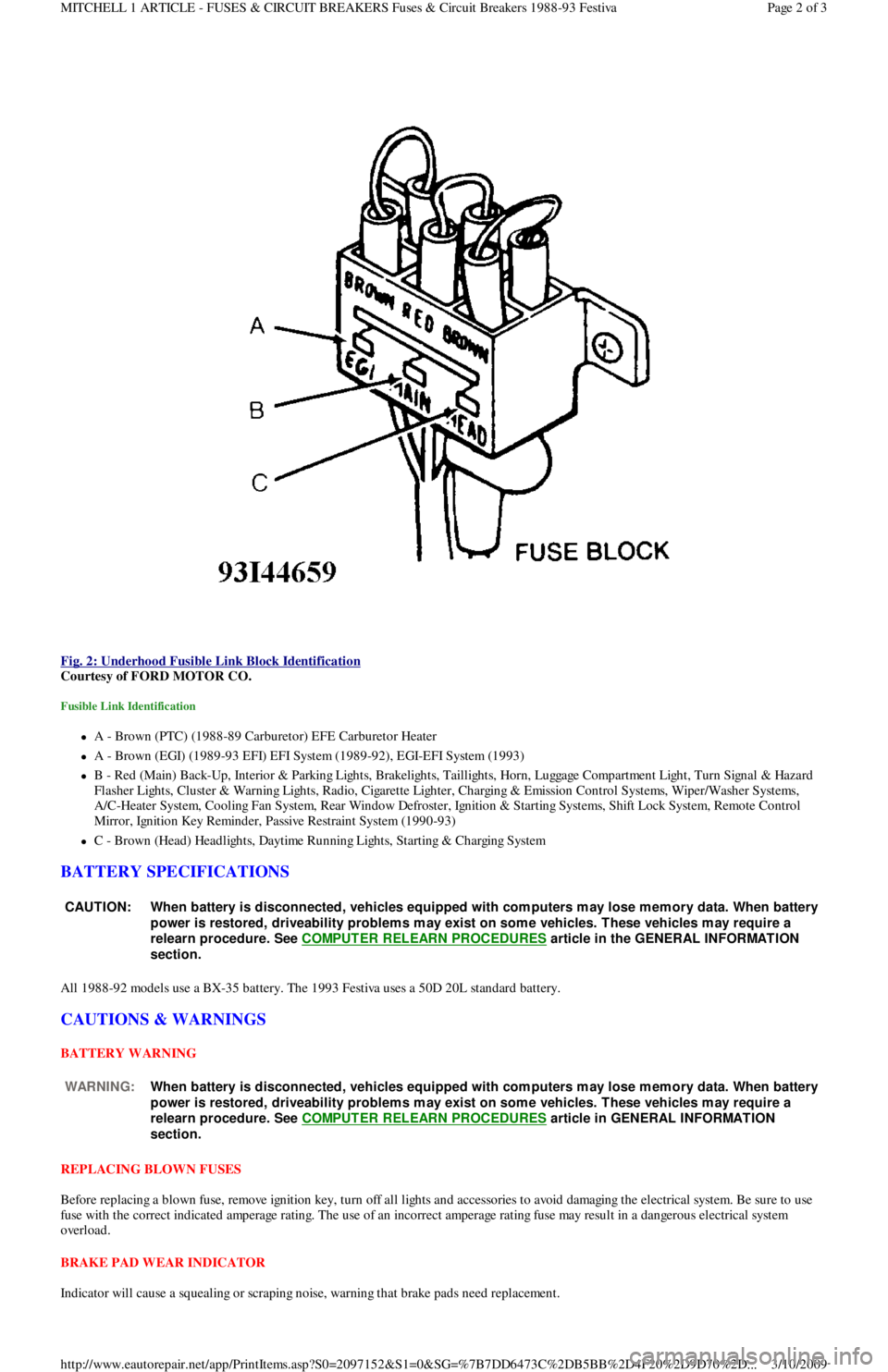
Fig. 2: Underhood Fusible Link Block Identification
Courtesy of FORD MOTOR CO.
Fusible Link Identification
A - Brown (PTC) (1988-89 Carburetor) EFE Carburetor Heater
A - Brown (EGI) (1989-93 EFI) EFI System (1989-92), EGI-EFI System (1993)
B - Red (Main) Back-Up, Interior & Parking Lights, Brakelights, Taillights, Horn, Luggage Compartment Light, Turn Signal & Hazard
F l a sh e r Ligh t s, C l u st e r & Wa r n in g Ligh t s, R a d io , C iga r e t t e Ligh t e r , C h a r gin g & E missio n C o n t r o l S yst e ms, Wip e r / Wa sh e r S yst e ms,
A/C-Heater System, Cooling Fan System, Rear Window Defroster, Ignition & Starting Systems, Shift Lock System, Remote Control
Mirror, Ignition Key Reminder, Passive Restraint System (1990-93)
C - Brown (Head) Headlights, Daytime Running Lights, Starting & Charging System
BATTERY SPECIFICATIONS
All 1988-92 models use a BX-35 battery. The 1993 Festiva uses a 50D 20L standard battery.
CAUTIONS & WARNINGS
BATTERY WARNING
REPLACING BLOWN FUSES
Before replacing a blown fuse, remove ignition key, turn off all lights and accessories to avoid damaging the electrical system. Be sure to use
fuse with the correct indicated amperage rating. The use of an incorrect amperage rating fuse may result in a dangerous electrical system
overload.
BRAKE PAD WEAR INDICATOR
Indicator will cause a squealing or scraping noise, warning that brake pads need replacement.
CAUT ION: When battery is disconnected, vehicles equipped with com puters m ay lose m em ory data. When battery
power is restored, driveability problem s m ay exist on som e vehicles. T hese vehicles m ay require a
relearn procedure. See COMPUTER RELEARN PROCEDURES
article in the GENERAL INFORMAT ION
section.
WARNING:When battery is disconnected, vehicles equipped with com puters m ay lose m em ory data. When battery
power is restored, driveability problem s m ay exist on som e vehicles. T hese vehicles m ay require a
relearn procedure. See COMPUTER RELEARN PROCEDURES
article in GENERAL INFORMAT ION
section.
Page 2 of 3 MITCHELL 1 ARTICLE - FUSES & CIRCUIT BREAKERS Fuses & Circuit Breakers 1988-93 Festiva
3/10/2009 http://www.eautorepair.net/app/PrintItems.asp?S0=2097152&S1=0&SG=%7B7DD6473C%2DB5BB%2D4F20%2D9D70%2D
...
Page 66 of 454

Autolamp Control RelayHeadlight Systems; Daytime Running Lights
Automatic Shutdown (ASD) RelayEngine Performance; Generators & Regulators
Autostick SwitchEngine Performance
Auxiliary Battery RelayGenerators & Regulators
Back-Up LightsBack-Up Lights; Exterior Lights
Barometric (BARO) Pressure SensorEngine Performance
BatteryPower Distribution
Battery Temperature SensorEngine Performance
Body Control ModuleBody Control Computer; Anti-Theft System; Daytime Running
Lights; Engine Performance; Headlight Systems; Warning Systems
Boost Control SolenoidEngine Performance
Boost SensorEngine Performance
Brake Fluid Level SwitchAnalog Instrument Panels
Brake On/Off (BOO) SwitchCruise Control Systems; Engine Performance; Shift Interlock
Systems
Buzzer ModuleWarning Systems
Camshaft Position (CMP) SensorEngine Performance
Central Control ModuleAnti-Theft System
ClockspringAir Bag Restraint System; Cruise Control Systems; Steering
Column Switches
Clutch Pedal Position SwitchStarters
Clutch Start SwitchStarters
Combination MeterAnalog Instrument Panels
Constant Control Relay Module (CCRM)Engine Performance; Electric Cooling Fans
Convenience CenterPower Distribution; Illumination/Interior Lights
Convertible Top MotorPower Convertible Top
Convertible Top SwitchPower Convertible Top
Crankshaft Position (CKP) SensorEngine Performance
Cruise Control ModuleCruise Control Systems
Cruise Control SwitchCruise Control Systems
Condenser Fan Relay(s)Electric Cooling Fans
Data Link Connector (DLC)Engine Performance
Da yt ime R u n n in g Ligh t s M o d u l eDaytime Running Lights; Exterior Lights
Defogger RelayRear Window Defogger
Diagnostic Energy Reserve Module (DERM)Air Bag Restraint System
Discriminating Sensor (Air Bag)Air Bag Restraint System
DistributorEngine Performance
Door Lock ActuatorsPower Door Locks; Remote Keyless Entry
Door Lock Relay(s)Power Door Locks
Electrochromic MirrorPower Mirrors
Electronic Level Control (ELC) Height SensorElectronic Suspension
Electronic Level Control (ELC) ModuleElectronic Suspension
Engine Coolant Temperature (ECT) Sending UnitAnalog Instrument Panels
Engine Coolant Temperature (ECT) SensorEngine Performance
Engine Control ModuleEngine Performance; Generators & Regulators; Starters
ETACS ECUWarning Systems; Power Windows; Remote Keyless Entry
Evaporative (EVAP) Emissions CanisterEngine Performance
EVAP Canister Purge SolenoidEngine Performance
EVAP Canister Vent SolenoidEngine Performance
Exhaust Gas Recirculation (EGR) ValveEngine Performance
Fuel Tank Vacuum SensorEngine Performance
F o g Ligh t sHeadlight Systems; Daytime Running Lights
F o g Ligh t R e l a yHeadlight Systems; Daytime Running Lights
Fuel Door Release SolenoidPower Fuel Door Release
Fuel Gauge Sending UnitAnalog Instrument Panels
Fuel InjectorsEngine Performance
Fuel PumpEngine Performance
Fuel Pump RelayEngine Performance; Power Distribution
Fuse/Relay BlockPower Distribution
Fusible LinksPower Distribution; Generators & Regulators; Starters
GeneratorGenerators & Regulators; Engine Performance; Power Distribution
Generic Electronic Module (GEM)Body Control Modules; Electronic Suspension
Glow Plug RelayEngine Performance
Glow PlugsEngine Performance
GroundsGround Distribution
Headlight Door ModuleHeadlight Doors
Headlight RelayHeadlight Systems; Daytime Running Lights
HeadlightsHeadlight Systems; Daytime Running Lights
Heated Oxygen Sensor(s) (HO2S)Engine Performance
Heated Windshield Control ModuleHeated Windshields
Page 4 of 6 MITCHELL 1 ARTICLE - GENERAL INFORMATION Using Mitchell1's Wiring Diagrams
3/10/2009 http://www.eautorepair.net/app/PrintItems.asp?S0=2097152&S1=0&SG=%7B959286D2%2D3A85%2D4BFC%2D9C5C%2D
...
Page 67 of 454

Height SensorElectronic Suspension
HornsSteering Column Switches
Horn RelaySteering Column Switches
Idle Air Control (IAC) Motor/ValveEngine Performance
Ignition Coil(s)Engine Performance
Ignition Key Lock CylinderAnti-Theft System
Ignition ModuleEngine Performance
Ignition SwitchPower Distribution; Engine Performance; Generators &
Regulators; Starters
Illuminated Entry ModuleIllumination/Interior Lights
Illumination LightsIllumination/Interior Lights
Impact SensorAir Bag Restraint System
Inertia Fuel Shutoff SwitchEngine Performance
In h ib it Rel ayStarters
Instrument ClusterAnalog Instrument Panels
Intake Air Temperature (IAT) SensorEngine Performance
Interior LightsIllumination/Interior Lights
In t erl o ck Swit chStarters
Junction BlockPower Distribution
Keyless Entry ReceiverRemote Keyless Entry
Key Reminder SwitchStarters
Knock SensorEngine Performance
Lamp Control ModuleExterior Lights
License Plate LampExterior Lights
Lighting Control ModuleLighting Control Modules; Anti-Theft System; Daytime Running
Lights; Headlight Systems
Lower RelayPower Convertible Top
Malfunction Indicator Light (MIL)Engine Performance; Instrument Panels
Manifold Absolute Pressure (MAP) SensorEngine Performance
Mass Airflow (MAF) SensorEngine Performance
Mega FuseGenerators & Regulators
Memory Seat/Mirror ModuleMemory Systems
M ir r o r De fo gge rRear Window Defogger
Moon Roof MotorPower Moon Roof
Moon Roof RelayPower Moon Roof
Multi-Function Control ModuleWarning Systems
Neutral Safety SwitchStarters
Oil Level SwitchEngine Performance
Oil Pressure Switch/Sending UnitAnalog Instrument Panels; Engine Performance
Overhead ConsoleOverhead Console
Oxygen Sensor(s) (O2S)Engine Performance
Parking Brake SwitchAnalog Instrument Panels
Park LightsExterior Lights
Park/Neutral Position SwitchStarters; Engine Performance; Anti-Theft System; Body Control
Module
Perimeter Lighting Control RelayExterior Lights
Power AmplifierPower Antennas
Power Antenna ModulePower Antennas
Power Antenna MotorPower Antennas
Power Distribution CenterPower Distribution; Generators & Regulators; Starters
Power Door Lock MotorsPower Door Locks
Power Mirror MotorsPower Mirrors; Memory Systems
Power Sliding Door ControllerPower Sliding Side Door
Power Seat MotorsPower Seats; Memory Systems
Power Steering Pressure SwitchEngine Performance
Power Top MotorPower Convertible Top
Power Top Relay(s)Power Convertible Top
Powertrain Control ModuleEngine Performance; Analog Instrument Panels; Cruise Control
Systems; Data Link Connectors; Generators & Regulators; Starters
Power Window MotorsPower Windows
Power Window Relay(s)Power Windows
Radiator Fan Motor(s)Electric Cooling Fans
Radiator Fan Relay(s)Engine Performance; Electric Cooling Fans;
Rainsense ModuleWiper/Washer Systems
Raise RelayPower Convertible Top
Remote Anti-Theft Personality (RAP) ModuleAnti-Theft System; Starters; Warning Systems
Seat Belt PretensionersAir Bag Restraint System
Seat Belt Retractor SolenoidPassive Restraints
Seat Belt SwitchAir Bag Restraint System; Passive Restraints
Shift Interlock SolenoidShift Interlock Systems
Page 5 of 6 MITCHELL 1 ARTICLE - GENERAL INFORMATION Using Mitchell1's Wiring Diagrams
3/10/2009 http://www.eautorepair.net/app/PrintItems.asp?S0=2097152&S1=0&SG=%7B959286D2%2D3A85%2D4BFC%2D9C5C%2D
...
Page 279 of 454
2. Turn test switch knob to ON position (current through switch). Road test vehicle with vehicle accessories on (radio, air conditioner, etc).
After road test, turn ignition switch to LOCKED position and remove key. Connect ammeter terminals to test switch terminals. See Fig.
1. Select 10-amp scale.
3. Turn off all electrical accessories. Turn off interior lights, underhood lamp, trunk light, illuminated entry, etc. To avoid damaging
ammeter or obtaining a false meter reading, all accessories must be off before turning test switch knob to OFF position.
4. Turn test switch knob to OFF position to allow current to flow through ammeter. If meter reads wrong polarity, turn test switch to ON
position and reverse leads. Turn test switch to OFF position. Observe current reading. If reading is less than 2 amps, turn test switch to
ON position to keep electrical circuits powered-up.
5. Select low amp scale. Switch lead to the correct meter position. Turn test switch to OFF position and compare results to normal current
draw. See GENERAL MOTORS PARASITIC LOAD TABLE (MILLIAMPS)
. If current draw is unusually high for the vehicle's
overall electrical system, remove system fuses one at a time until current draw returns to normal.
6. Turn test switch to ON position each time door is opened or fuse is removed. Turn switch to OFF position to read current draw va l u e
through meter. When the cause of excessive current drain has been located and repaired, remove test switch and reconnect negative
battery cable to the negative battery terminal.
INTERMITTENT PARASITIC LOAD PROBLEMS
Intermittent parasitic load can occur because of a memory device that does not power down with ignition off. With an intermittent parasitic
load, battery draw can be greater than 1.0 amp.
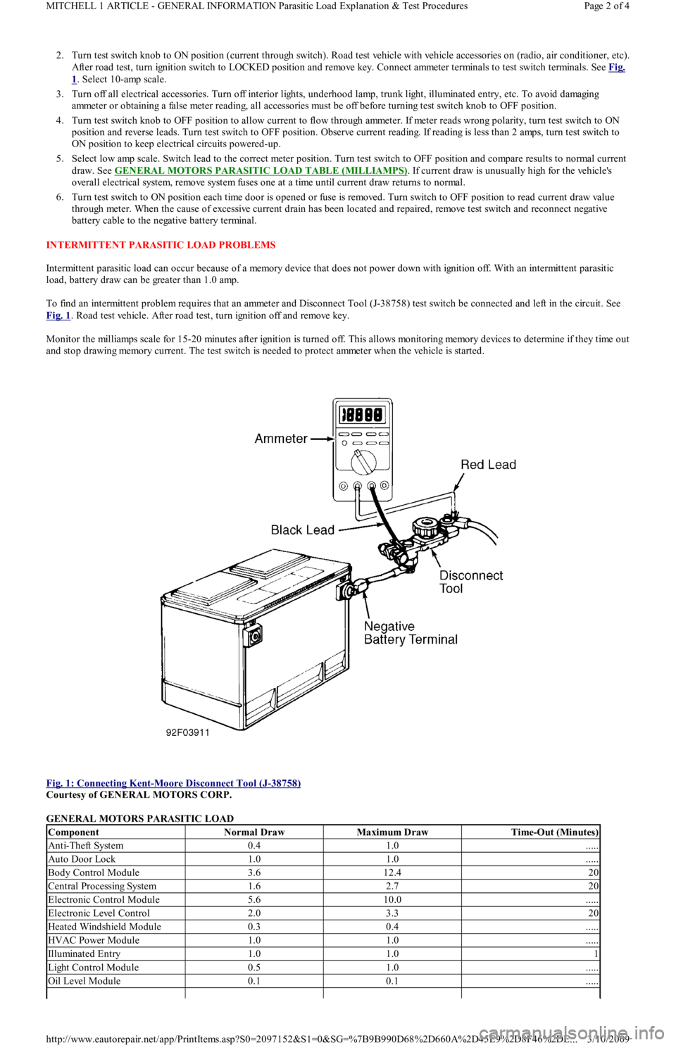
To find an intermittent problem requires that an ammeter and Disconnect Tool (J-38758) test switch be connected and left in the circuit. See
Fig. 1
. Road test vehicle. After road test, turn ignition off and remove key.
Monitor the milliamps scale for 15-20 minutes after ignition is turned off. This allows monitoring memory devices to determine if they time out
and stop drawing memory current. The test switch is needed to protect ammeter when the vehicle is started.
Fig. 1: Connecting Kent
-Moore Disconnect Tool (J-38758)
Courtesy of GENERAL MOTORS CORP.
GENERAL MOTORS PARASITIC LOAD
ComponentNormal DrawMaximum DrawTime-Out (Minutes)
Anti-Theft System0.41.0.....
Auto Door Lock1.01.0.....
Body Control Module3.612.420
Central Processing System1.62.720
Electronic Control Module5.610.0.....
Electronic Level Control2.03.320
Heated Windshield Module0.30.4.....
HVAC Power Module1.01.0.....
Illuminated Entry1.01.01
Light Control Module0.51.0.....
Oil Level Module0.10.1.....
Page 2 of 4 MITCHELL 1 ARTICLE - GENERAL INFORMATION Parasitic Load Explanation & Test Procedures
3/10/2009 http://www.eautorepair.net/app/PrintItems.asp?S0=2097152&S1=0&SG=%7B9B990D68%2D660A%2D45E9%2D8F46%2DE
...
Page 372 of 454
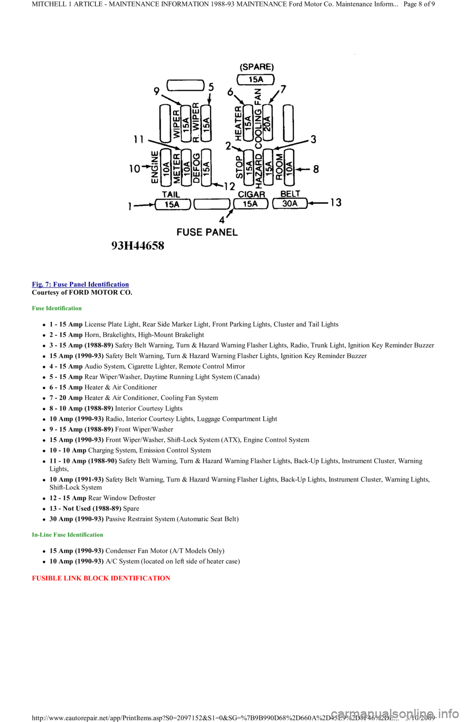
Fig. 7: Fuse Panel Identification
Courtesy of FORD MOTOR CO.
Fuse Identification
1 - 15 Amp License Plate Light, Rear Side Marker Light, Front Parking Lights, Cluster and Tail Lights
2 - 15 Amp Horn, Brakelights, High-Mount Brakelight
3 - 15 Amp (1988-89) Safety Belt Warning, Turn & Hazard Warning Flasher Lights, Radio, Trunk Light, Ignition Key Reminder Buzzer
15 Amp (1990-93) Safety Belt Warning, Turn & Hazard Warning Flasher Lights, Ignition Key Reminder Buzzer
4 - 15 Amp Audio System, Cigarette Lighter, Remote Control Mirror
5 - 15 Amp Rear Wiper/Washer, Daytime Running Light System (Canada)
6 - 15 Amp Heater & Air Conditioner
7 - 20 Amp Heater & Air Conditioner, Cooling Fan System
8 - 10 Amp (1988-89) Interior Courtesy Lights
10 Amp (1990-93) R a d io , In t e r io r C o u r t e sy Ligh t s, Lu gga ge C o mp a r t me n t Ligh t
9 - 15 Amp (1988-89) Front Wiper/Washer
15 Amp (1990-93) Front Wiper/Washer, Shift-Lock System (ATX), Engine Control System
10 - 10 Amp Charging System, Emission Control System
11 - 10 Amp (1988-90) Safety Belt Warning, Turn & Hazard Warning Flasher Lights, Back-Up Lights, Instrument Cluster, Warning
Lights,
10 Amp (1991-93) Safety Belt Warning, Turn & Hazard Warning Flasher Lights, Back-Up Lights, Instrument Cluster, Warning Lights,
Shift-Lock System
12 - 15 Amp Rear Window Defroster
13 - Not Used (1988-89) Spare
30 Amp (1990-93) Passive Restraint System (Automatic Seat Belt)
In-Line Fuse Identification
15 Amp (1990-93) Condenser Fan Motor (A/T Models Only)
10 Amp (1990-93) A/C System (located on left side of heater case)
FUSIBLE LINK BLOCK IDENTIFICATION
Page 8 of 9 MITCHELL 1 ARTICLE - MAINTENANCE INFORMATION 1988-93 MAINTENANCE Ford Motor Co. Maintenance Inform...
3/10/2009 http://www.eautorepair.net/app/PrintItems.asp?S0=2097152&S1=0&SG=%7B9B990D68%2D660A%2D45E9%2D8F46%2DE
...
Page 373 of 454
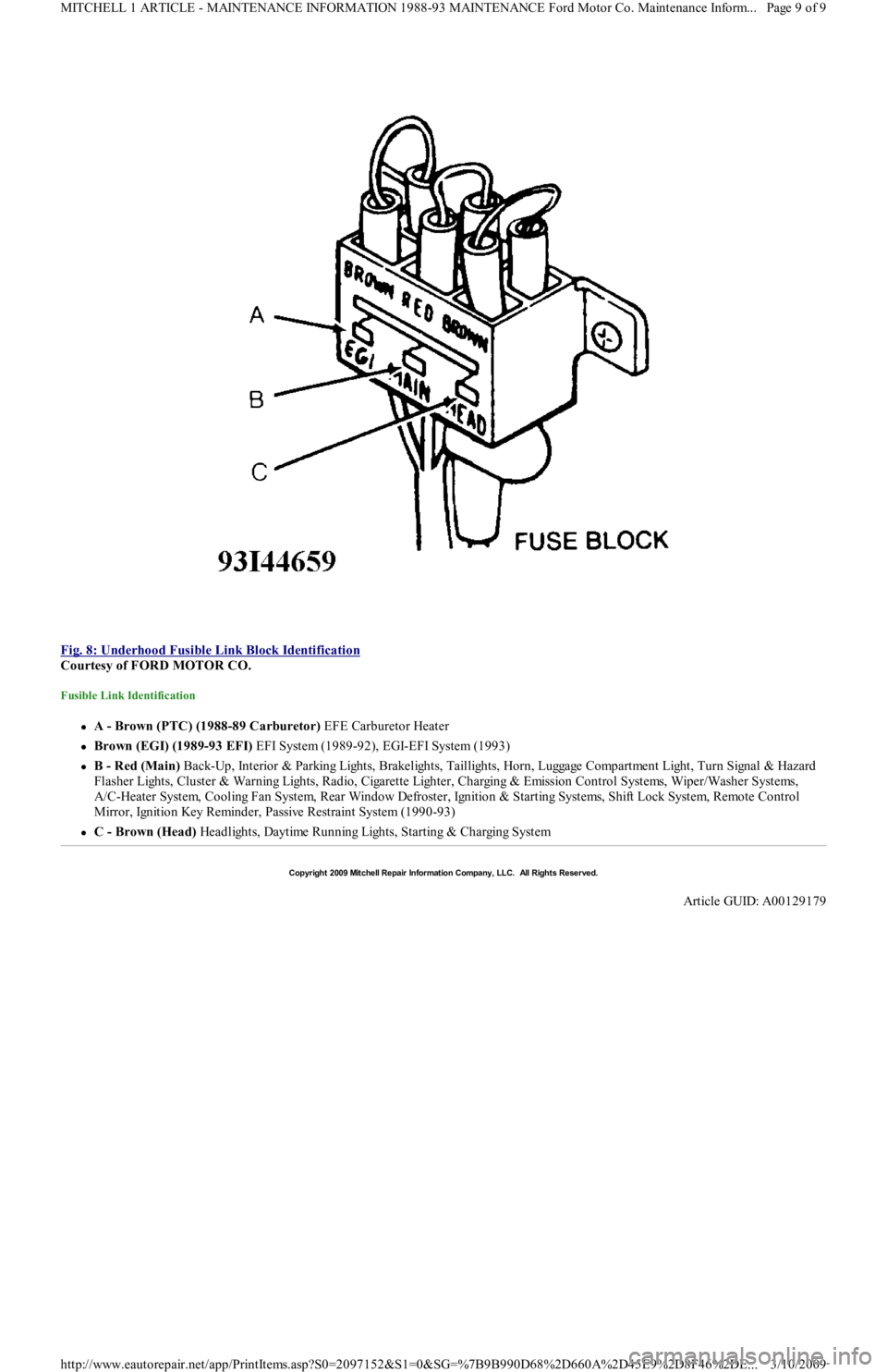
Fig. 8: Underhood Fusible Link Block Identification
Courtesy of FORD MOTOR CO.
Fusible Link Identification
A - Brown (PTC) (1988-89 Carburetor) EFE Carburetor Heater
Brown (EGI) (1989-93 EFI) EFI System (1989-92), EGI-EFI System (1993)
B - Red (Main) Back-Up, Interior & Parking Lights, Brakelights, Taillights, Horn, Luggage Compartment Light, Turn Signal & Hazard
F l a sh e r Ligh t s, C l u st e r & Wa r n in g Ligh t s, R a d io , C iga r e t t e Ligh t e r , C h a r gin g & E missio n C o n t r o l S yst e ms, Wip e r / Wa sh e r S yst e ms,
A/C-Heater System, Cooling Fan System, Rear Window Defroster, Ignition & Starting Systems, Shift Lock System, Remote Control
Mirror, Ignition Key Reminder, Passive Restraint System (1990-93)
C - Brown (Head) Headlights, Daytime Running Lights, Starting & Charging System
Copyr ight 2009 Mitchell Repair Information Company, LLC. All Rights Reserved.
Article GUID: A00129179
Page 9 of 9 MITCHELL 1 ARTICLE - MAINTENANCE INFORMATION 1988-93 MAINTENANCE Ford Motor Co. Maintenance Inform...
3/10/2009 http://www.eautorepair.net/app/PrintItems.asp?S0=2097152&S1=0&SG=%7B9B990D68%2D660A%2D45E9%2D8F46%2DE
...
Page 414 of 454
Differential Noise
ATF contaminated or level incorrect. Bearings worn or has excessive preload. Teeth on gears worn or damaged or has excessive backlash.
TESTING
PARK/NEUTRAL SWITCH TEST
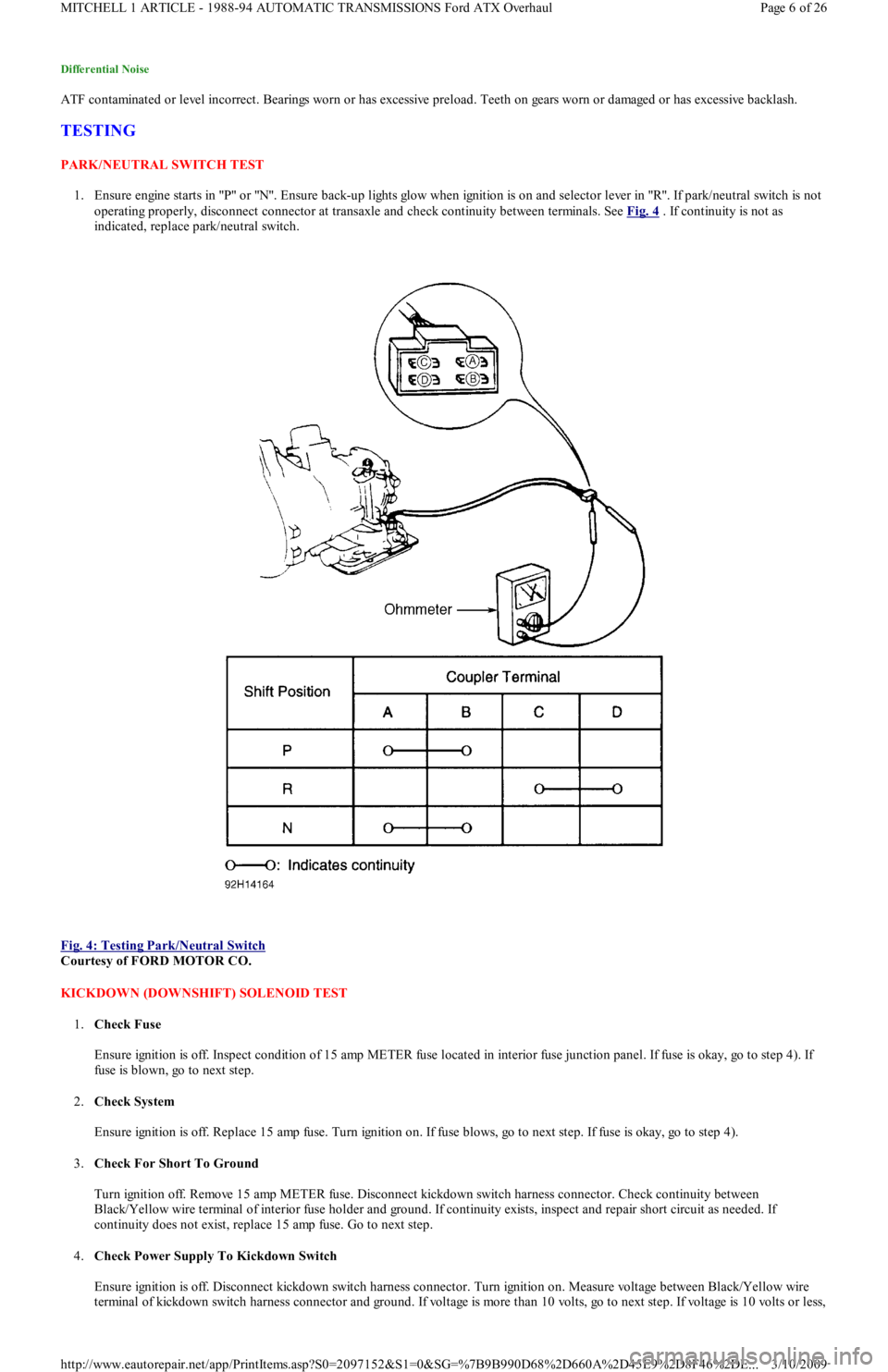
1. Ensure engine starts in "P" or "N". Ensure back-up lights glow when ignition is on and selector lever in "R". If park/neutral switch is not
operating properly, disconnect connector at transaxle and check continuity between terminals. See Fig. 4
. If continuity is not as
indicated, replace park/neutral switch.
Fig. 4: Testing Park/Neutral Switch
Courtesy of FORD MOTOR CO.
KICKDOWN (DOWNSHIFT) SOLENOID TEST
1.Check Fuse
Ensure ignition is off. Inspect condition of 15 amp METER fuse located in interior fuse junction panel. If fuse is okay, go to step 4). If
fuse is blown, go to next step.
2.Check System
Ensure ignition is off. Replace 15 amp fuse. Turn ignition on. If fuse blows, go to next step. If fuse is okay, go to step 4).
3.Check For Short To Ground
Turn ignition off. Remove 15 amp METER fuse. Disconnect kickdown switch harness connector. Check continuity between
Black/Yellow wire terminal of interior fuse holder and ground. If continuity exists, inspect and repair short circuit as needed. If
continuity does not exist, replace 15 amp fuse. Go to next step.
4.Check Power Supply To Kickdown Switch
Ensure ignition is off. Disconnect kickdown switch harness connector. Turn ignition on. Measure voltage between Black/Yellow wire
terminal of kickdown switch harness connector and ground. If voltage is more than 10 volts, go to next step. If voltage is 10 volts or less,
Page 6 of 26 MITCHELL 1 ARTICLE - 1988-94 AUTOMATIC TRANSMISSIONS Ford ATX Overhaul
3/10/2009 http://www.eautorepair.net/app/PrintItems.asp?S0=2097152&S1=0&SG=%7B9B990D68%2D660A%2D45E9%2D8F46%2DE
...