1991 FORD FESTIVA Index
[x] Cancel search: IndexPage 101 of 454
Back To Article
ENGINE OVERHAUL
1991-92 FORD MOT OR CO. ENGINES 1.3L & 1.6L 4-Cylinder
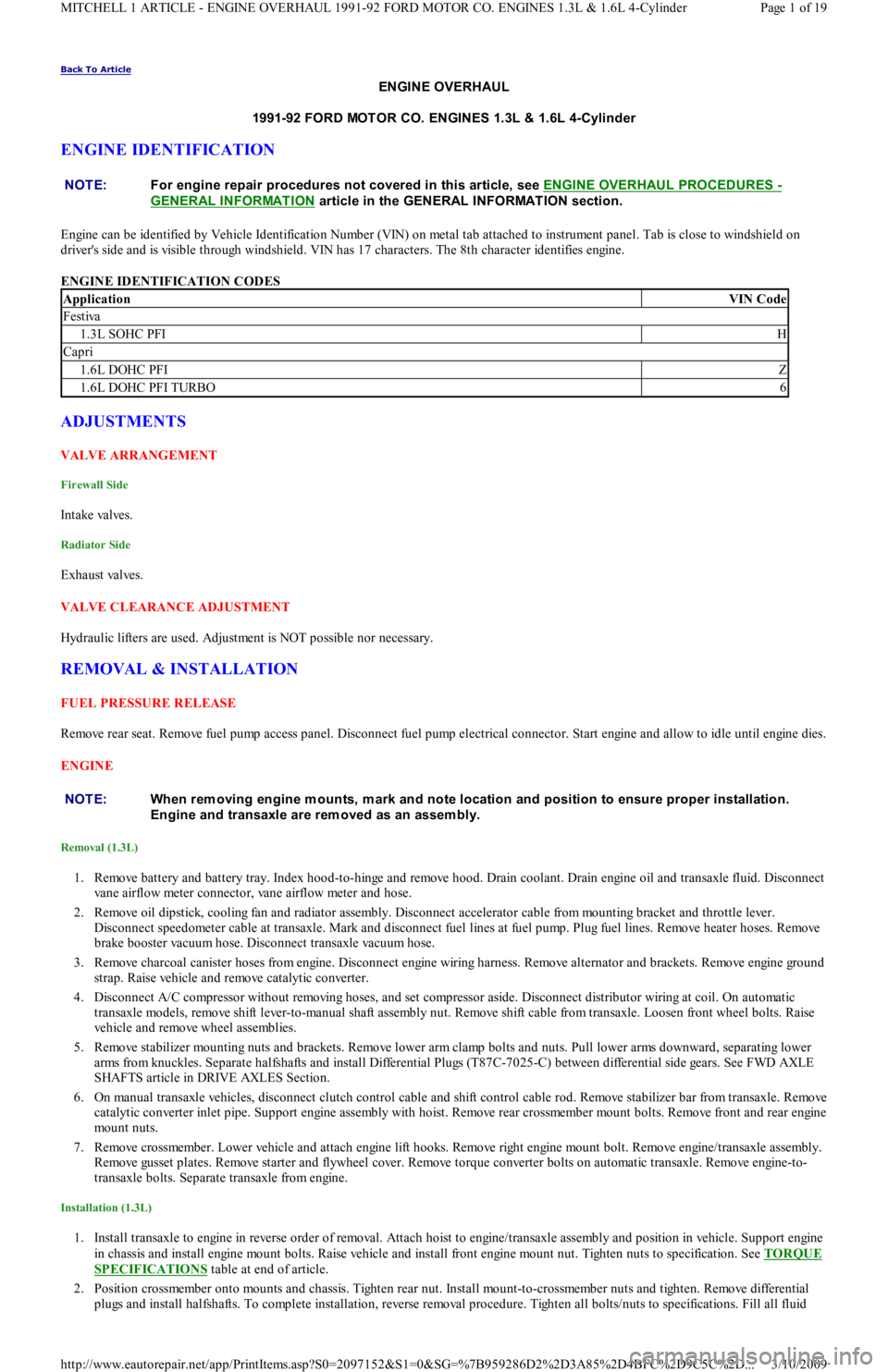
ENGINE IDENTIFICATION
Engine can be identified by Vehicle Identification Number (VIN) on metal tab attached to instrument panel. Tab is close to windshield on
driver's side and is visible through windshield. VIN has 17 characters. The 8th character identifies engine.
ENGINE IDENTIFICATION CODES
ADJUSTMENTS
VALVE ARRANGEMENT
Firewall Side
In t ake val ves.
Radiator Side
Exhaust valves.
VALVE CLEARANCE ADJUSTMENT
Hydraulic lifters are used. Adjustment is NOT possible nor necessary.
REMOVAL & INSTALLATION
FUEL PRESSURE RELEASE
Remove rear seat. Remove fuel pump access panel. Disconnect fuel pump electrical connector. Start engine and allow to idle until engine dies.
ENGINE
Removal (1.3L)
1. Remove battery and battery tray. Index hood-to-hinge and remove hood. Drain coolant. Drain engine oil and transaxle fluid. Disconnect
vane airflow meter connector, vane airflow meter and hose.
2. Remove oil dipstick, cooling fan and radiator assembly. Disconnect accelerator cable from mounting bracket and throttle lever.
Disconnect speedometer cable at transaxle. Mark and disconnect fuel lines at fuel pump. Plug fuel lines. Remove heater hoses. Remove
brake booster vacuum hose. Disconnect transaxle vacuum hose.
3. Remove charcoal canister hoses from engine. Disconnect engine wiring harness. Remove alternator and brackets. Remove engine ground
strap. Raise vehicle and remove catalytic converter.
4. Disconnect A/C compressor without removing hoses, and set compressor aside. Disconnect distributor wiring at coil. On automatic
transaxle models, remove shift lever-to-manual shaft assembly nut. Remove shift cable from transaxle. Loosen front wheel bolts. Raise
vehicle and remove wheel assemblies.
5. Remove stabilizer mounting nuts and brackets. Remove lower arm clamp bolts and nuts. Pull lower arms downward, separating lower
arms from knuckles. Separate halfshafts and install Differential Plugs (T87C-7025-C) between differential side gears. See FWD AXLE
SHAFTS article in DRIVE AXLES Section.
6. On manual transaxle vehicles, disconnect clutch control cable and shift control cable rod. Remove stabilizer bar from transaxle. Remove
catalytic converter inlet pipe. Support engine assembly with hoist. Remove rear crossmember mount bolts. Remove front and rear engine
mount nuts.
7. Remove crossmember. Lower vehicle and attach engine lift hooks. Remove right engine mount bolt. Remove engine/transaxle assembly.
Remove gusset plates. Remove starter and flywheel cover. Remove torque converter bolts on automatic transaxle. Remove engine-to-
transaxle bolts. Separate transaxle from engine.
Installation (1.3L)
1. Install transaxle to engine in reverse order of removal. Attach hoist to engine/transaxle assembly and position in vehicle. Support engine
in chassis and install engine mount bolts. Raise vehicle and install front engine mount nut. Tighten nuts to specification. See TORQUE
SPECIFICATIONS table at end of article.
2. Position crossmember onto mounts and chassis. Tighten rear nut. Install mount-to-crossmember nuts and tighten. Remove differential
plugs and install halfshafts. To complete installation, reverse removal procedure. Tighten all bolts/nuts to specifications. Fill all fluid NOTE:For engine repair procedures not covered in this article, see ENGINE OVERHAUL PROCEDURES
-
GENERAL INFORMATION
article in the GENERAL INFORMAT ION section.
ApplicationVIN Code
Festiva
1.3L SOHC PFIH
Capri
1.6L DOHC PFIZ
1.6L DOHC PFI TURBO6
NOTE:When rem oving engine m ounts, m ark and note location and position to ensure proper installation.
Engine and transaxle are rem oved as an assem bly.
Page 1 of 19 MITCHELL 1 ARTICLE - ENGINE OVERHAUL 1991-92 FORD MOTOR CO. ENGINES 1.3L & 1.6L 4-Cylinder
3/10/2009 http://www.eautorepair.net/app/PrintItems.asp?S0=2097152&S1=0&SG=%7B959286D2%2D3A85%2D4BFC%2D9C5C%2D
...
Page 104 of 454

1. Position new gasket on exhaust manifold, and install turbocharger onto studs. Install 4 retaining nuts and tighten to specification. See
TORQUE SPECIFICATIONS
table at end of article.
2. Remove oil supply line from turbocharger. Position new (2-piece) exhaust gasket on cylinder head with heavy gasket installed first .
Carefully position turbocharger assembly in engine compartment and slide exhaust manifold on studs. Position heater tube bracket onto
exhaust stud. Install 11 retaining nuts onto exhaust manifold and tighten to specification. See TORQUE SPECIFICATIONS
table at
end of article. Tighten heater tube clamp bolt securely.
3. Raise vehicle. Position new gasket and install 2 retaining bolts on heater tube outlet. Install 2 retaining bolts into turbocharger support
bracket and tighten bolts to specification.
4. Connect coolant return hose. Connect oil return hose and secure with clamp. Position exhaust pipe onto turbocharger, and start nuts
and washers. Install 2 retaining bolts on exhaust hanger at engine. Slide on 2 rubber exhaust hangers at catalytic converter. Tighten
exhaust pipe retaining nuts to specification. Lower vehicle.
5. Install retaining bolt and brass washers on oil supply line, carefully position oil line into vehicle and hand-start bolt into engine block.
Connect and finger tighten oil line to turbocharger. Tighten oil line bolt and oil supply line on turbocharger to specification.
6. Connect coolant supply hose. Position air cleaner duct tube on turbocharger and tighten clamp. Install 2 screws retaining air cleaner
duct tube. Position power steering pump bracket on engine, and install 2 retaining bolts and one retaining nut. Tighten to specification.
Position power steering pump on mounting bracket, and install though bolt and adjuster. Connect lower radiator hose. Install power
steering belt. Position upper heat shield and install 2 retaining bolts finger tight.
7. Position lower heat shield and install three retaining bolts finger tight. Tighten all heat shield bolts to specification. Connect O2 sensor
and install connector into its retaining clip. See TORQUE SPECIFICATIONS
table at end of article. Position intercooler hose on
turbocharger and secure with clamp. Install throttle body air intake tube. Connect negative battery cable. Refill cooling system.
CYLINDER HEAD
Removal (1.3L)
1. Disconnect battery ground cable. Mark and disconnect fuel lines at fuel pump. Remove accessory belts, water pump pulley, crankshaft
pulley, timing belt covers, timing belt tensioner, timing belt, valve cover and exhaust and intake manifolds. Drain cooling system.
2. Mark and remove electrical connectors and vacuum hoses. Remove spark plug wires from spark plugs, and remove spark plugs. Remove
distributor cap. Disconnect vacuum hoses and distributor wiring.
3. Index distributor-to-mount position and remove hold-down bolt. Remove distributor assembly. Remove engine ground strap. Remove
front and rear engine lifting hooks. Remove upper radiator hose, by-pass hose and bracket.
4. Remove bolts retaining rocker arm shaft. Remove rocker arm assemblies. Remove cylinder head bolts. Remove head and gasket.
Inspection (1.3L)
1. Thoroughly clean and check gasket mating surface of cylinder head and block. Check cylinder for cracks, nicks, burrs or damage. Using
a straightedge and feeler gauge, check warpage over entire gasket area. Ensure cylinder head and/or block warpage does not
exceed .006" (.15 mm).
2. If warpage exceeds .006" (.15 mm), machine cylinder head and/or block gasket surface. Maximum machining allowed is .008" (.20 mm).
If more machining is required, replace block and/or cylinder head.
Installation (1.3L)
1. Place new head gasket properly on block. Carefully place cylinder head in position on block. Install head bolts. Tighten bolts in
sequence and in 2 steps. See Fig. 1
.
2. While tightening rocker arm shaft, slide shaft springs away from retaining bolt to prevent pinching springs. Tighten rocker arm shaft bolts
in sequence and to specification. See Fig. 5
. To complete installation, reverse removal procedure. Tighten all bolts/nuts to
specification. Fill all fluids to proper levels. NOTE:T urbocharger-to-exhaust m anifold m ounting nuts are of special quality. Ensure correct nuts are
used.
NOTE:Ensure one brass washer is positioned on each side of oil line fitting.
NOTE:Feed O2 sensor wire through upper heat shield. Install wire retainer under LH bolt.
NOTE:If turbocharger was replaced: Disconnect ignition coil, crank engine for 20 seconds, connect ignition
coil, start engine and run at idle for 30 seconds and check for leaks.
NOTE:If original tim ing belt is being reused, m ark direction of rotation for installation reference.
Page 4 of 19 MITCHELL 1 ARTICLE - ENGINE OVERHAUL 1991-92 FORD MOTOR CO. ENGINES 1.3L & 1.6L 4-Cylinder
3/10/2009 http://www.eautorepair.net/app/PrintItems.asp?S0=2097152&S1=0&SG=%7B959286D2%2D3A85%2D4BFC%2D9C5C%2D
...
Page 226 of 454
ENGINE PERFORMANCE
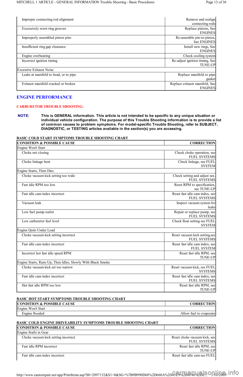
CARBURETOR TROUBLE SHOOTING:
BASIC COLD START SYMPTOMS TROUBLE SHOOTING CHART
BASIC HOT START SYMPTOMS TROUBLE SHOOTING CHART
BASIC COLD ENGINE DRIVEABILITY SYMPTOMS TROUBLE SHOOTING CHART
Improper connecting rod alignmentRemove and realign
connecting rods
E xc e ssive l y wo r n r in g gr o o ve sReplace pistons, See
ENGINES
Improperly assembled piston pinsRe-assemble pin-to-piston,
See ENGINES
Insufficient ring gap clearanceInstall new rings, See
ENGINES
Engine overheatingCheck cooling system
Incorrect ignition timingRe-adjust ignition timing, See
TUNE-UP
Excessive Exhaust Noise
Leaks at manifold to head, or to pipeReplace manifold or pipe
ga ske t
Exhaust manifold cracked or brokenReplace exhaust manifold, See
ENGINES
NOTE:This is GENERAL inform ation. This article is not intended to be specific to any unique situation or
individual vehicle configuration. T he purpose of this T rouble Shooting inform ation is to provide a list
of com m on causes to problem sym ptom s. For m odel-specific T rouble Shooting, refer to SUBJECT ,
DIAGNOST IC, or T EST ING articles available in the section(s) you are accessing.
CONDITION & POSSIBLE CAUSECORRECTION
Engine Won't Start
Choke not closingCheck choke operation, see
FUEL SYSTEMS
Choke linkage bentCheck linkage, see FUEL
SYSTEM
Engine Starts, Then Dies
Choke vacuum kick setting too wideCheck setting and adjust see,
FUEL SYSTEMS
Fast idle RPM too lowReset RPM to specification,
see TUNE-UP
Fast idle cam index incorrectReset fast idle cam index, see
FUEL SYSTEMS
Vacuum leakInspect vacuum system for
leaks
Low fuel pump outletRepair or replace pump, see
FUEL SYSTEMS
Low carburetor fuel levelCheck float setting see FUEL
SYSTEM
Engine Quits Under Load
Choke vacuum kick setting incorrectReset vacuum kick setting,see
FUEL SYSTEMS
Fast idle cam index incorrectReset fast idle cam index, see
FUEL SYSTEM
Incorrect hot fast idle speed RPMReset fast idle RPM, see
TUNE-UP
Engine Starts, Runs Up, Then Idles, Slowly With Black Smoke
Choke vacuum kick set too narrowReset vacuum kick, see FUEL
SYSTEMS
Fast idle cam index incorrectReset fast idle cam index, see
FUEL SYSTEMS
Hot fast idle RPM too lowReset fast idle RPM, see
TUNE-UP
CONDITION & POSSIBLE CAUSECORRECTION
Engine Won't Start
Engine floodedAllow fuel to evaporate
CONDITION & POSSIBLE CAUSECORRECTION
Engine Stalls in Gear
Choke vacuum kick setting incorrectReset choke vacuum kick, see
FUEL SYSTEMS
Fast idle RPM incorrectReset fast idle RPM, see
TUNE-UP
Fast idle cam index incorrectReset fast idle cam see FUEL
Page 13 of 36 MITCHELL 1 ARTICLE - GENERAL INFORMATION Trouble Shooting - Basic Procedures
3/10/2009 http://www.eautorepair.net/app/PrintItems.asp?S0=2097152&S1=0&SG=%7B9B990D68%2D660A%2D45E9%2D8F46%2DE
...
Page 376 of 454
the WHEEL ALIGNMENT section.
OVERHAUL
STEERING GEAR
Disassembly
1. With steering gear removed from vehicle, place steering gear in a soft-jawed vise. Mark threaded portion of tie rod for reassembly.
Remove tie rod ends. Remove tie rod boots. Remove lock pins from both ends of rack. See Fig. 1
.
2. Remove tie rod ball socket from end of rack. Remove both tie rods. Remove lock nut from yoke plug. Remove yoke plug, spring and
yoke support. Use a small screwdriver to remove pinion oil seal from pinion shaft. Remove pinion bearing snap ring.
3. Remove pinion and bearing assembly. If necessary use Valve Body Puller (T78P-3504-B) to remove pinion and bearing assembly.
Remove rack from pinion side of housing. If lower pinion bearing needs replacing, use Blind Hole Bearing Puller (D80L-100-L) and
Slide Hammer (T50T-100-A) to remove.
4. Press bushing lock tabs into the 3 slots located at end of rack housing. Use Blind Hole Bearing Puller (D80L-100-L), to remove rack
support bushing from right end of rack housing.
Inspection
1. Check rubber boots, ball bearings and tooth surface of rack for wear or damage. Using a dial indicator and "V" blocks, check rack for
straightness. Maximum allowable runout is 0.012" (0.3 mm). If rack support bushings are worn, use a screwdriver to release the tab lock
on the side opposite the pinion. Use blind hole Bearing Puller (D80L-100R) with slide hammer to remove bushing.
2. Check tie rod ball joints for smooth operation. Replace parts as necessary. Check sliding surface of rack support and gear housing for
cracks or damage. Check rack bushing for excessive wear. Replace entire gear housing assembly if any of these parts are worn or
damaged.
Reassembly
1. Apply lithium grease to ball bearing, roller bearing, inside of gear housing, lip of oil seal, sliding surface and back of rack support,
sliding surface of rack bushing, rack pinion teeth and ball joints. Install rack support bushing into right end of rack housing. Ensure lock
tabs engage with slots in housing.
2. If previously removed, install a new lower pinion bearing using a bushing installer or a piece of wooden dowel stock. Carefully insert
non-toothed side of rack into left end of rack housing, with rack teeth facing pinion bore. Position rack in housing so rack protrudes
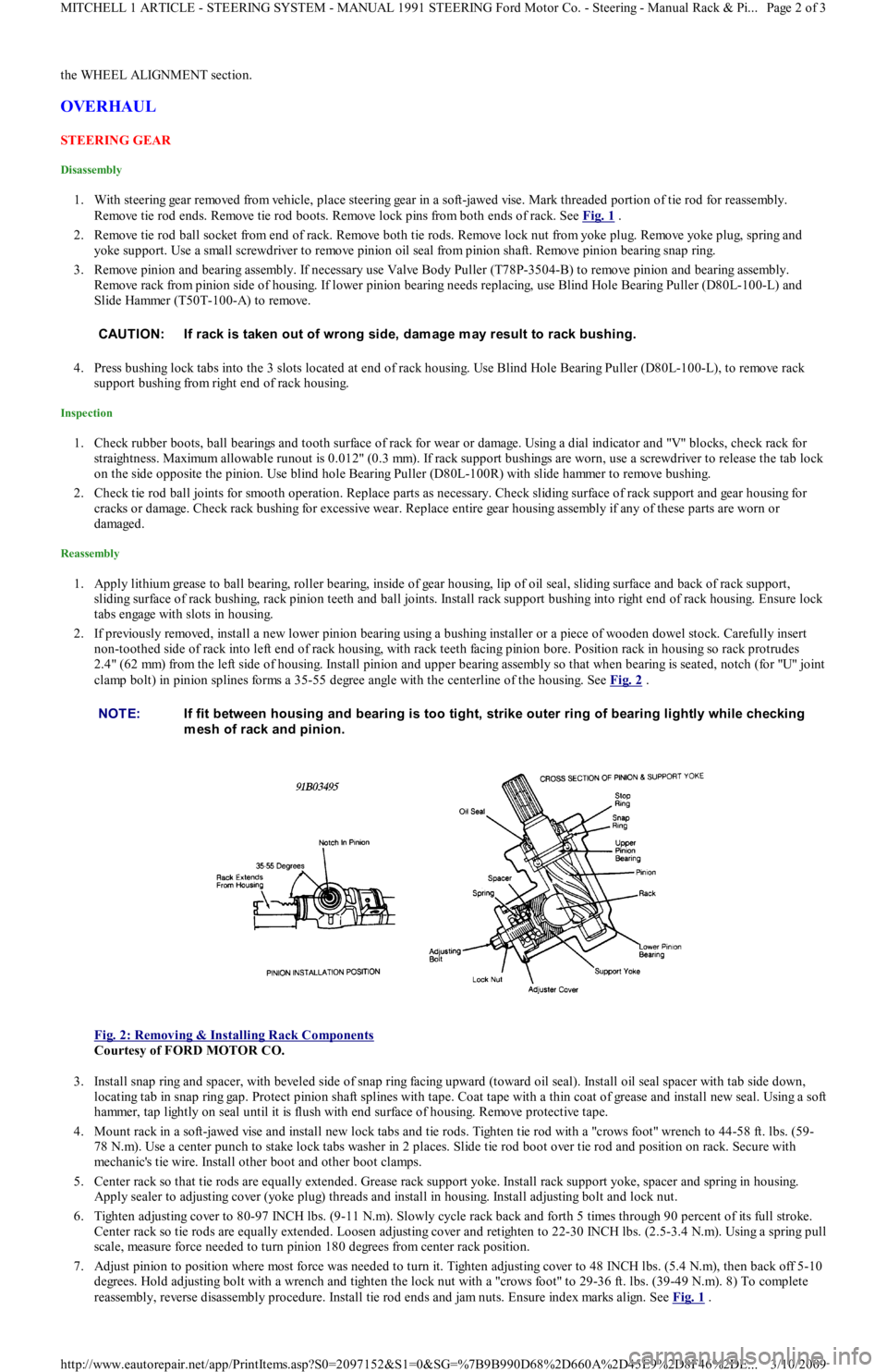
2.4" (62 mm) from the left side of housing. Install pinion and upper bearing assembly so that when bearing is seated, notch (for "U" joint
clamp bolt) in pinion splines forms a 35-55 degree angle with the centerline of the housing. See Fig. 2
.
Fig. 2: Removing & Installing Rack Components
Courtesy of FORD MOTOR CO.
3. Install snap ring and spacer, with beveled side of snap ring facing upward (toward oil seal). Install oil seal spacer with tab side down,
locating tab in snap ring gap. Protect pinion shaft splines with tape. Coat tape with a thin coat of grease and install new seal. Using a soft
hammer, tap lightly on seal until it is flush with end surface of housing. Remove protective tape.
4. Mount rack in a soft-jawed vise and install new lock tabs and tie rods. Tighten tie rod with a "crows foot" wrench to 44-58 ft. lbs. (59-
78 N.m). Use a center punch to stake lock tabs washer in 2 places. Slide tie rod boot over tie rod and position on rack. Secure with
mechanic's tie wire. Install other boot and other boot clamps.
5. Center rack so that tie rods are equally extended. Grease rack support yoke. Install rack support yoke, spacer and spring in housing.
Apply sealer to adjusting cover (yoke plug) threads and install in housing. Install adjusting bolt and lock nut.
6. Tighten adjusting cover to 80-97 INCH lbs. (9-11 N.m). Slowly cycle rack back and forth 5 times through 90 percent of its full stroke.
Center rack so tie rods are equally extended. Loosen adjusting cover and retighten to 22-30 INCH lbs. (2.5-3.4 N.m). Using a spring pull
scale, measure force needed to turn pinion 180 degrees from center rack position.
7. Adjust pinion to position where most force was needed to turn it. Tighten adjusting cover to 48 INCH lbs. (5.4 N.m), then back off 5-10
degrees. Hold adjusting bolt with a wrench and tighten the lock nut with a "crows foot" to 29-36 ft. lbs. (39-49 N.m). 8) To comp l et e
reassembly, reverse disassembly procedure. Install tie rod ends and jam nuts. Ensure index marks align. See Fig. 1
. CAUT ION: If rack is taken out of wrong side, dam age m ay result to rack bushing.
NOTE:If fit between housing and bearing is too tight, strike outer ring of bearing lightly while checking
m esh of rack and pinion.
Page 2 of 3 MITCHELL 1 ARTICLE - STEERING SYSTEM - MANUAL 1991 STEERING Ford Motor Co. - Steering - Manual Rack & Pi
...
3/10/2009 http://www.eautorepair.net/app/PrintItems.asp?S0=2097152&S1=0&SG=%7B9B990D68%2D660A%2D45E9%2D8F46%2DE
...
Page 381 of 454
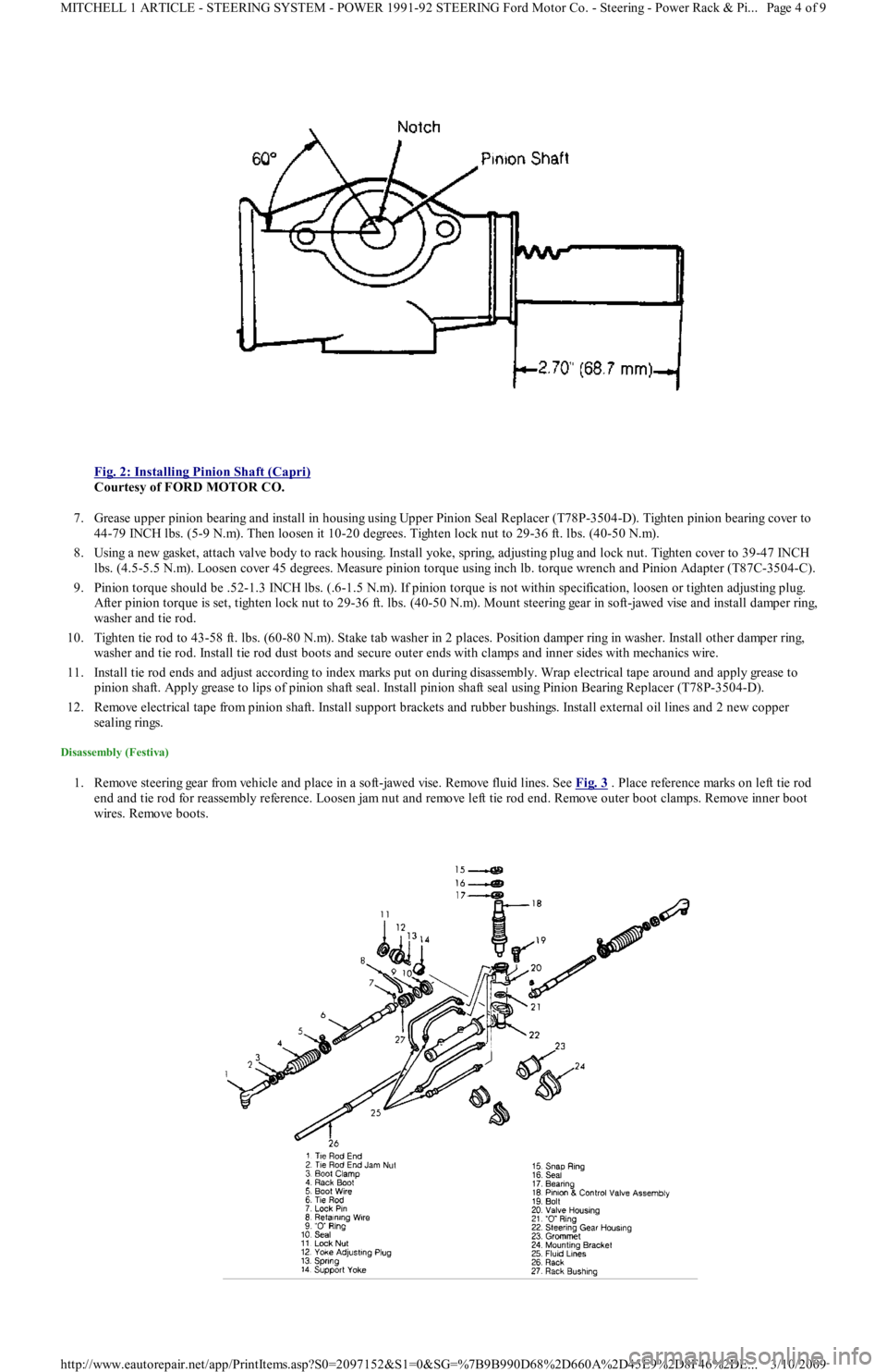
Fig. 2: Installing Pinion Shaft (Capri)
Courtesy of FORD MOTOR CO.
7. Grease upper pinion bearing and install in housing using Upper Pinion Seal Replacer (T78P-3504-D). Tighten pinion bearing cover to
44-79 INCH lbs. (5-9 N.m). Then loosen it 10-20 degrees. Tighten lock nut to 29-36 ft. lbs. (40-50 N.m).
8. Using a new gasket, attach valve body to rack housing. Install yoke, spring, adjusting plug and lock nut. Tighten cover to 39-47 INCH
lbs. (4.5-5.5 N.m). Loosen cover 45 degrees. Measure pinion torque using inch lb. torque wrench and Pinion Adapter (T87C-3504-C).
9. Pinion torque should be .52-1.3 INCH lbs. (.6-1.5 N.m). If pinion torque is not within specification, loosen or tighten adjusting plug.
After pinion torque is set, tighten lock nut to 29-36 ft. lbs. (40-50 N.m). Mount steering gear in soft-jawed vise and install damper ring,
washer and tie rod.
10. Tighten tie rod to 43-58 ft. lbs. (60-80 N.m). Stake tab washer in 2 places. Position damper ring in washer. Install other damper ring,
washer and tie rod. Install tie rod dust boots and secure outer ends with clamps and inner sides with mechanics wire.
11. Install tie rod ends and adjust according to index marks put on during disassembly. Wrap electrical tape around and apply grease to
pinion shaft. Apply grease to lips of pinion shaft seal. Install pinion shaft seal using Pinion Bearing Replacer (T78P-3504-D).
12. Remove electrical tape from pinion shaft. Install support brackets and rubber bushings. Install external oil lines and 2 new copper
sealing rings.
Disassembly (Festiva)
1. Remove steering gear from vehicle and place in a soft-jawed vise. Remove fluid lines. See Fig. 3 . Place reference marks on left tie rod
end and tie rod for reassembly reference. Loosen jam nut and remove left tie rod end. Remove outer boot clamps. Remove inner boot
wires. Remove boots.
Page 4 of 9 MITCHELL 1 ARTICLE - STEERING SYSTEM - POWER 1991-92 STEERING Ford Motor Co. - Steering - Power Rack & Pi
...
3/10/2009 http://www.eautorepair.net/app/PrintItems.asp?S0=2097152&S1=0&SG=%7B9B990D68%2D660A%2D45E9%2D8F46%2DE
...
Page 398 of 454
1. Using Installer (T77F-1217-A), Driver Handle (T80T-4000-W) or proper sized brass drift and hammer, install inner and outer bearing
races. Pack bearings and hub area with Lubricant (C1AZ-1959D-B, C, D or E).
2. Position inner bearing in bearing hub. Lubricate grease seal lips and install seal. Ensure bearings and hub have sufficient lubricant. Place
brake drum bearings and hub assembly on spindle. To prevent damage to grease seal and spindle threads, ensure hub is correctly
centered on spindle.
3. Install outer bearing, washer and new lock nut. Stake lock nut with a blunt chisel. Adjust bearing preload. See ADJUSTMENTS &
INSPECTION.
SPINDLE
Removal & Installation (Capri)
Remove wheel, caliper and brake rotor. Loosen spindle-to-strut attaching bolts. Loosen outer rear control arm common bolt and nut. Remove
spindle-to-strut mount bolts and common control arm bolt. Remove spindle from strut. To install, reverse removal procedure.
Removal & Installation (Festiva)
Remove brake drum assembly. Remove 4 spindle attaching nuts located on inboard side of torsion beam. Support backing plate with wire and
remove spindle. To install, reverse removal procedure. Tighten spindle attaching nuts to 32-45 ft. lbs. (43-61 N.m).
STRUTS
Removal & Installation (Capri)
1. Remove wheel, caliper and brake rotor. Remove trailing arm bolt and spindle-to-strut attaching bolts. Put index mark on strut rubber
mounting bracket. Remove upper strut attaching nuts from inside vehicle. Remove strut.
2. Compress strut coil spring with Spring Compressor (T18P-5310-A) or similar. Remove strut nut while spring is compressed. Remove
rubber mounting bracket, upper and lower spring seats. Slowly release coil spring and remove spring compressor. Remove coil spring,
dust boot and rebound bumpers. To install, reverse removal procedure.
Removal (Festiva)
1. Raise and support vehicle. Remove rear wheels. Using Spring Compressor (T81P-5310-A), compress spring to unload strut. Remove rear
quarter trim panel from cargo compartment.
2. Remove jam nut and flanged nut from strut rod. Remove bushing washer and upper bushing. Remove strut lower end mounting bolt
from wheel support arm. Remove strut and separate it from spring and seat insulator. Remove lower bushing and jounce bumper seat
from strut rod. Slide jounce bumper and shield off strut. See Fig. 3
. NOTE:Nut m ust be replaced if lock flange splits or cracks during staking process. DO NOT stake with a sharp-
edged tool.
Page 3 of 7 MITCHELL 1 ARTICLE - SUSPENSION - REAR 1991-92 SUSPENSION Rear
3/10/2009 http://www.eautorepair.net/app/PrintItems.asp?S0=2097152&S1=0&SG=%7B9B990D68%2D660A%2D45E9%2D8F46%2DE
...